Table of Contents
Advertisement
AIR CONDITIONER
4-unit multi-split type,
5-unit multi-split type
DESIGN & TECHNICAL MANUAL
INDOOR
ASHG07KGTB
ASHG09KGTB
ASHG12KGTB
ASHG14KGTB
ABHG18KRTA
ABHG22KRTA
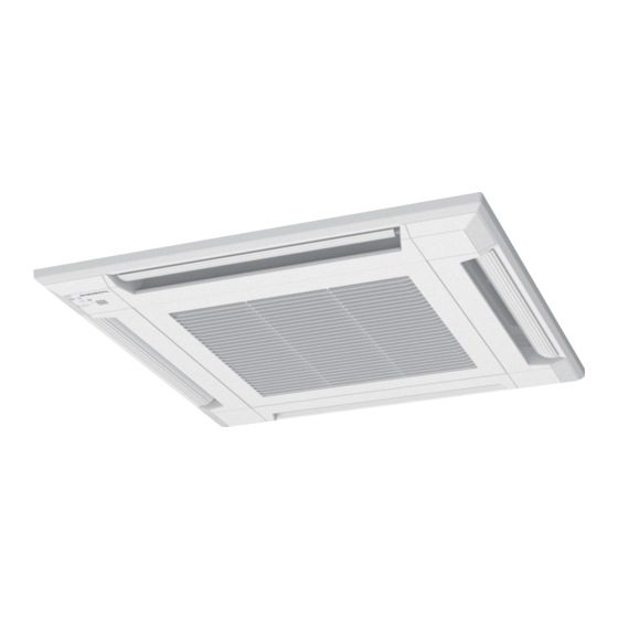
AUXG07KVLA
AUXG09KVLA
AUXG12KVLA
AUXG14KVLA
AUXG18KVLA
AUXG22KVLA
ASHG18KMTB
ASHG22KMTB
ASHG24KMTB
AGHG09KVCA
AGHG12KVCA
AGHG14KVCA
ARXG07KSLAP
ARXG07KLLAP
ARXG09KSLAP
ARXG09KLLAP
ARXG12KSLAP
ARXG12KLLAP
ARXG14KSLAP
ARXG14KLLAP
ARXG18KSLAP
ARXG18KLLAP
ASHG07KMCC
ASHG09KMCC
ASHG12KMCC
ASHG14KMCC
OUTDOOR
ARXG22KMLB
ASHG07KETA
ASHG07KETA-B
ASHG09KETA
ASHG09KETA-B
ASHG12KETA
ASHG12KETA-B
ASHG14KETA
ASHG14KETA-B
AOHG30KBTA4
AOHG36KBTA5
DR_MU025EG_01
2020.11.20
Advertisement
Table of Contents


Need help?
Do you have a question about the AUXG07KVLA and is the answer not in the manual?
Questions and answers