Table of Contents
Advertisement
Quick Links
SPLIT TYPE
AIR CONDITIONER
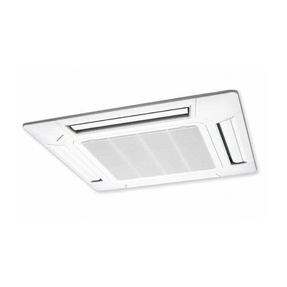
CASSETTE TYPE (50Hz)
Indoor unit
AUYG45LRLA
AUYG54LRLA
CONTENTS
SPECIFICATIONS . . . . . . . . . . . . . . . . . . .
DIMENSIONS. . . . . . . . . . . . . . . . . . . . . . .
REFRIGERANT SYSTEM DIAGRAM . . . .
CIRCUIT DIAGRAM . . . . . . . . . . . . . . . . . .
INDOOR PCB CIRCUIT DIAGRAM . . . . . .
ERROR DETECTION. . . . . . . . . . . . . . . .
PARTS (DECORATION PANEL) . . . . . . .
PARTS (INDOOR UNIT) . . . . . . . . . . . . .
PARTS (OUTDOOR UNIT) . . . . . . . . . . .
ACCESSORIES . . . . . . . . . . . . . . . . . . . .
Outdoor unit
AOYG45LETL
AOYG54LETL
1
2
3
4
5
9
. . . .
15
19
22
26
29
Advertisement
Table of Contents

Related Manuals for General AUYG45LRLA


Summary of Contents for General AUYG45LRLA
-
Page 1: Table Of Contents
SPLIT TYPE AIR CONDITIONER CASSETTE TYPE (50Hz) Indoor unit Outdoor unit AUYG45LRLA AOYG45LETL AUYG54LRLA AOYG54LETL CONTENTS SPECIFICATIONS ....DIMENSIONS..... . . -
Page 2: Specifications
SPECIFICATIONS ELECTRICAL DATA NOISE LEVEL Cooling & Heating 46 dB TYPE High 47 dB AUYG45LRLA AUYG54LRLA INDOOR UNIT Medium 42 dB 43 dB INDOOR UNIT OUTDOOR UNIT AOYG45LETL AOYG54LETL 40 dB 41 dB COOLING CAPACITY 12.5 kW 13.3 kW Quiet... -
Page 3: Dimensions
DIMENSIONS OUTDOOR UNIT (Unit : mm) INDOOR UNIT Drain pipe Gas pipe Liquid pipe 900 mm 330 mm 795 mm DECORATION PANEL 400 mm air flow 650 mm 795 (Hanging bolt position) 2013.02.15... -
Page 4: Refrigerant System Diagram
REFRIGERANT SYSTEM DIAGRAM OUTDOOR UNIT INDOOR UNIT Refrigerant Pipe Pressure 15.88mm (5/8") Check Valve 3-way Valve Muffler Pressure Sensor 4-way Valve Heat Heat Check Exchanger Exchanger Valve High Pressure Accumulator Switch Muffler Compressor Refrigerant Pipe 9.52mm (3/8") Strainer Strainer Expansion 3-way Valve Valve Thermistor (Room) -
Page 5: Circuit Diagram
OUTDOOR UNIT HIGH PRESSURE SWITCH CN101 WHITE BLACK WHITE CN61 THERMISTOR ( OUTDOOR ) WHITE BLACK WHITE BLACK WHITE THERMISTOR ( PIPE TEMP. ) BLACK WHITE CN63 WHITE MAIN PCB BLACK CN401 CN40 THERMISTOR ( PIPE - MID. ) WHITE BLACK WHITE CIRCUIT DIAGRAM... -
Page 6: Indoor Pcb Circuit Diagram
INDOOR PCB CIRCUIT DIAGRAM THERMISTOR B02B-XASK-1-A ( ROOM TEMP. ) WHITE B02B-XAYK-1-A CONTROL UNIT YELLOW THERMISTOR AUYG45LRLA : EZ-0122RHSE BLACK B02B-XAKK-1-A BLACK ( PIPE TEMP. ) BLACK AUYG54LRLA : EZ-0122SHSE B5P-SHF-1AA WHITE INDICATOR PCB 2 (N) 15-1 ( OPTION ) - Page 7 INDOOR UNIT MAIN PCB AUYG45LRLA : K06AK-121BHSE-C1 AUYG54LRLA : K06AK-121CHSE-C1 R1 - R3 B02B-XASK-1-A 1SS355 10k <1/10W> x 3 THERMISTOR ( ROOM TEMP. ) I C8 FLOAT SWITCH 13.5V NJM7812 B03B-PASK-1 <1/10W> B02B-XAYK-1-A 1.0k B03B-XARK-1-A <F> <1/10W> <1/10W> DC SUPPLY 1.0k...
- Page 8 R103 340V D108 13.5V D2FL20U <RS-2W> T101 C108 ZFT22B03-C 4700 C113 R111 <FNS> I C26-14 1000/ R104 <1/10W> 330k D102 <2W> F101 1SR139-600 C114 3.15A 0.01 250V <KH> C109 D107 220p C115 L101 Q101 D106 FC51FL x 2 <BN> RD16 D101 0.01 LF101...
- Page 9 INDOOR UNIT INDICATOR PCB ( OPTION ) K06AG-1000HSE-D0 R201 220 <1/4W> D201 SLR-325MC GREEN CN201 S07B-PASK-2 R202 390 <1/4W> D202 SLR-325DC ORANGE R203 220 <1/4W> D203 SLR-325MC GREEN TO MAIN PCB C202 C201 <F> SW201 EVQPAG04K PHA201 P I C-37143TH5 2013.01.21...
-
Page 10: Outdoor Pcb Circuit Diagram
OUTDOOR PCB CIRCUIT DIAGRAM INVERTER ASSEMBLY AOYG45LETL : EZ-0121HHUE AOYG54LETL : EZ-0121KHUE EMI FILTER RFC-13 F103 F104 W100 EMI FILTER AC250V 30A POWER SOURCE UL1015 AC250V 3.15A ZCAT2132-1130 AWG12 AC230V BLACK W102 UL1015 50Hz TM101 AWG12 UL1015 W101 ORANGE AWG12 WHITE FILTER PCB INDOOR UNIT... - Page 11 OUTDOOR UNIT MAIN PCB - 1 AOYG45LETL : K10BS-1203HUE-C1 AOYG54LETL : K10BS-1204HUE-C1 C167, C168 R163 340V 330p <CH> <1/10W> 12V-2 D200 L152 D3F60 BLm31PG121 C152 D153 3-1747052-4 220/ RF101L2S YELLOW C214 D203 D231 AC I N L155 R219, R220 2200p 1SS355 RF301B2S 1.8k <1/4W>...
- Page 12 OUTDOOR UNIT MAIN PCB - 2 AOYG45LETL : K10BS-1203HUE-C1 AOYG54LETL : K10BS-1204HUE-C1 CN12 B02B-XAKK-1-A C802 L800 15V-2 BLACK 15V-2 P_EX_OUT1 340V Q801 CN800 BL02Rn1 <B> EX. OUT 1 DTA143EUA I C10-7 B6P-VH-B WHITE D801 uLN2003 R800 RD24FM FTR-F3 <1/10W> BLm18AG601 DC FAN MOTOR 1 R801 C800...
- Page 13 OUTDOOR UNIT TRANSISTOR PCB ( I P M ) K10AY-1003HUE-TR0 C209 - C211, C221 C222 C302 0.1 <F> 100/ L300 <F> BL02Rn1 TM303 C332 TM101 86028 D307 86028 C161 RD24FM <F> <X7R> I PM-G TM102 TM304 86028 BLACK 86028 D100 LL25XB60 I C301 TM305...
- Page 14 OUTDOOR UNIT POWER SUPPLY PCB K10BR-1000HUE-FL0 JM100 - JM102 TM103 86028 W111 ORANGE W112 ORANGE TM100 86028 VA100, VA101 FH106 FH107 K100 L101 L102 L100 470V <TNR> H-0017-2 x 2 DW12D1-O (M) RCH3818-022PF07 n200500K RCH3818-022PF07 W100 W102 ORANGE BLACK C104 C106 F103 0.022...
- Page 15 OUTDOOR UNIT CAPACITOR PCB K05FB-1000HUE-P0 WHITE YELLOW C200 - C203 R200 660/ 220k 450V <2W> BLUE VIOLET POWER_G OUTDOOR UNIT INDICATOR PCB K10BC-1000YUE-D0 D401 SLR-325 <ORANGE> D402 SLR-325 <ORANGE> D403 SLR-325 <ORANGE> ( CN401-1 ) D404 SLR-325 <ORANGE> ( CN401-2 ) D405 SLR-325 ( CN401-3 ) <ORANGE>...
-
Page 16: Error Detection
ER R OR D E TEC TION Indoor unit Indoor unit Wired Wired OPERATION TIMER ECONOMY remote Description OPERATION TIMER ECONOMY remote Description INDOOR UNIT lamp lamp lamp lamp lamp lamp control control (green) (orange) (green) (green) (orange) (green) and WIRED REMOTE CONTROL Discharge temp. - Page 17 OUTDOOR UNIT Indicator PCB LEDs Buttons ERROR DETECTION Display when an error occurs. PUMP PEAK POWER ERROR DOWN NOISE MODE (L1) (L2) (L3) (L4) (L5) (L6) Blink (Hi speed) Check that the “ERROR” LED blinks, then press the [Enter] button once. For details, refer to the following table.
- Page 18 OUTDOOR UNIT TEST RUN Before the test run, refer to he figure and check the following items. Setting method Is the outdoor unit securely installed? Turn on the power of the outdoor unit and enter standby mode. Have you performed gas leakage inspection? PUMP PEAK (Connection joints of various pipes (flang connection, brazing))
- Page 19 OUTDOOR UNIT PUMP DOWN Procedure WARNING (1) Check the 3-way valves (both the liquid side and gas side) are opened. Never touch electrical components such as the terminal blocks except the button on (2) Turn the power on. the display board. It may cause a serious accident such as electric shock. PUMP PEAK During the pump-down operation, make sure that the compressor is turned off before...
-
Page 20: Parts (Decoration Panel)
PARTS DECORATION PANEL UTG-UGYA-W Ref. Description Part number Intake Grille Assy 9378565012 Intake Grille 9378249011 Long Life Filter 9378252011 Filter Guide 9378253018 Hook Bracket 9378435018 Grille Hook 9378250017 2012.04.26... - Page 21 DECORATION PANEL UTG-UGYA-W Ref. Description Part number Decoration Panel 9378242012 Corner Panel A 9378243019 Corner Panel (FUJITSU) 9378243026 Panel Cover A 9378261013 Panel Cover B 9378262010 Drain Cover 9378359017 2012.03.16...
- Page 22 DECORATION PANEL UTG-UGYA-W Ref. Description Part number Flap 9378254015 Poli Slider 9375541019 Joint C 9378357013 Step motor 9900467005 Gear A 9378256019 Motor Holder 9378255012 Joint A 9378258013 Joint B 9378259010 Gear B 9378257016 Joint Shaft 9378260016 Flap Spring 9378356016 2012.03.16...
-
Page 23: Parts (Indoor Unit)
PARTS INDOOR UNIT Ref. Description Part number Ref. Description Part number Top Plate Assy 9378395015 Motor, DC Brushless 9602716005 Cabinet A Sub Assy 9378594012 Motor Rubber 9378223011 Cabinet B Sub Assy 9378595019 Turbo Fan Assy 9378228016 Cabinet C Sub Assy 9378570016 Turbo Fan Washer 9378394018... - Page 24 INDOOR UNIT Ref. Description Part number Evaporator Total Assy 9378580053 Coupling Pipe Assy 9373038627 Wind Guide Board 9378236011 2012.03.16...
- Page 25 INDOOR UNIT Ref. Description Part number Sensor Holder 9378329010 Float Switch 9900465018 Pump Assy 9900464011 Drain Pump Holder B 9375518011 Pump Rubber 9378426016 Drain Hose 9378212015 Drain Port 9378213012 Drain Pan Assy 9378207011 Bell Mouth 9378227019 Terminal Wire Cover 9378548015 Drain Cap 9375502010 Drain Hose...
- Page 26 INDOOR UNIT Ref. Description Part number PCB Holder 9378205017 Power Supply PCB 9707398366 Main PCB (45) 9709245477 Main PCB (54) 9709245484 Terminal 3P 9306489045 Terminal 3P 9703345012 Thermistor Holder A 9378206014 Thermistor Holder B 9378330016 Room Thermistor 9900445010 Pipe Thermistor 9900470012 Remote Control 9318593013...
-
Page 27: Parts (Outdoor Unit)
PARTS OUTDOOR UNIT Ref. Description Parts number Ref. Description Parts number Top Panel Sub Assy 9374417056 Motor DC Brushless 9602843039 Front Panel Sub Assy 9374414109 Propeller Fan Assy 9366378020 Sevice Panel Sub Assy 9374415090 Condenser A Sub Assy 9374420261 Emblem Rear 9351355005 Condenser B Sub Assy 9374422081... - Page 28 OUTDOOR UNIT Control box Ref. Description Parts number Main PCB (AOYG45LETL) 9708690148 Main PCB (AOYG54LETL) 9708690155 Indicator PCB 9708678016 Terminal 9900203023 Filter PCB 9708688015 Thermistor 9704265012 Capacitor PCB 9707257083 Choke Coil 9900624019 ACTPM 9707592016 Transistor PCB 9708647043 Heat Sink 9380358008 Outdoor Thermistor 9900210069 Thermistor Assy (CN63)
- Page 29 OUTDOOR UNIT Ref. Description Parts number Ref. Description Parts number 3-way Valve Assy 9379079006 4-way Valve Assy 9374425235 3-way Valve Assy 9379077002 Discharge Pipe Assy 9371581248 Compressor 9810153005 Pressure Switch 9900186012 Accumulator 9379014021 Check Joint Assy 9372802038 Expansion Valve Coil 9970096044 Union joint Assy 9379068000...
-
Page 30: Accessories
ACCESSORIES INDOOR UNIT DECORATION PANEL Name and Shape Q'ty Part number Part number Name and Shape Q'ty Template For mounting decoration Hexigon (Carton top) For installing indoor unit 9378552029 0700087103 Screw panel Washer Screw For installing grille For installing indoor unit 0700132278 0700009037 holding wire... - Page 31 OPTIONAL PARTS Parts name and model name Parts name and model name IR receiver unit For air conditioner operation External connect kit Use to connect with various UTY-LRHYA2 UTY-XWZX peripheral devices and air conditioner PCB. Wired Remote Control For air conditioner operation Fresh air intake kit To take fresh air UTY-RNNYM...
Need help?
Do you have a question about the AUYG45LRLA and is the answer not in the manual?
Questions and answers