
Related Manuals for Ingenico Link 2500


Summary of Contents for Ingenico Link 2500
- Page 1 Link/2500 USER GUIDE INGENICO –28‐32 Boulevard de Grenelle – 75015 Paris ‐ FRANCE Tél. +33 (0)1 58 01 80 00 – Fax +33 (0)1 58 01 91 35 www.ingenico.com ...
-
Page 2: Table Of Contents
Changing the battery __________________________________________________________ 18 Recommendations _ ____________________________________________ 1 9 5.1. Safety ______________________________________________________________ 19 5.2. Security of your terminal ______________________________________________ 21 Standards ___________________________________________________ 22 Troubleshooting _____________________________________________ 23 USER GUIDE • 2/24 Copyright © 2012 Ingenico R11 900019007 000 02 All rights reserved ... -
Page 3: Introduction
WARRANTY / SECURITY Use only the power supply included with the product to ensure best performance and safety. Maintenance should only be provided by Ingenico authorized technician. Failure to comply with these instructions will void the manufacturer’s responsibility. This symbol indicates an important Warning. This symbol indicates a piece of advice. USER GUIDE • 3/24 ... - Page 4 Any Changes or modifications not expressly approved by the party responsible for compliance could void the user’s authority to operate the equipment. Tous les changements ou modifications non expressément approuvée par le responsable de la conformité pourrait vider l'utilisateur est habilité à exploiter l'équipement. USER GUIDE • 4/24 Copyright © 2012 Ingenico R11 900019007 000 02 All rights reserved ...
- Page 5 être testé et certifié à l'ic qu'il ne dépasse pas les limites d'exposition établies par l'ic, les tests pour chaque appareil sont effectués dans des postes et des endroits comme requis par l'ic. des manuels, ce dispositif a été testé et répond à l'ic de l'exposition aux rf directives. le dispositif doit être exploité avec distance minimale de 20 cm de l'organisme. non ‐ conformité avec les restrictions ci ‐ dessus peut entraîner l'exposition aux radiofréquences, en violation des directives USER GUIDE • 5/24 Copyright © 2012 Ingenico R11 900019007 000 02 All rights reserved ...
-
Page 6: Presentation
A battery pack disconnected User guide ADVICE Keep the packaging. It must be re‐used whenever the terminal is shipped. USER GUIDE • 6/24 Copyright © 2012 Ingenico R11 900019007 000 02 All rights reserved ... -
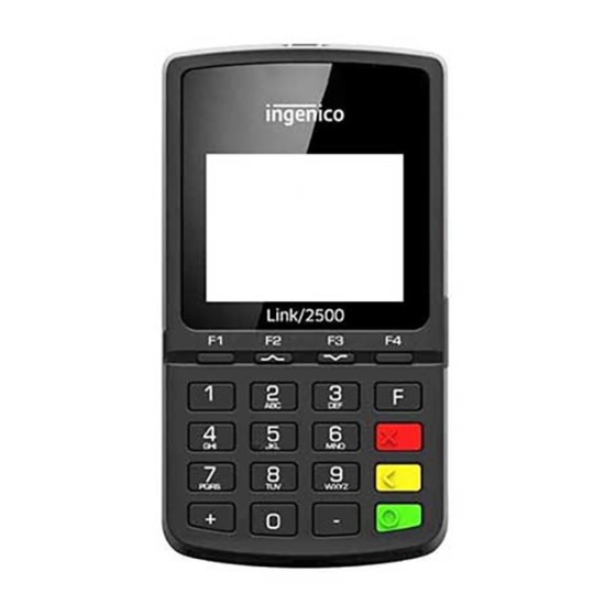
Page 7: Overview Of The Link/2500
Terminal unit 2’’4 LCD Display Magnetic card reader Contactless reader Smart card reader USER GUIDE • 7/24 Copyright © 2012 Ingenico R11 900019007 000 02 All rights reserved ... - Page 8 Model 1 (FCC ID: XKB‐L2500CLWIBT) Weight 155g (without battery) Dimensions (L x w x h) 129x70x17 mm Electrical mains network 100‐240VAC / 50‐60 Hz ‐ Class II equipment Type C USB serial link Connections on terminal Power connector USER GUIDE • 8/24 Copyright © 2012 Ingenico R11 900019007 000 02 All rights reserved ...
- Page 9 Special option: • Thinner • No battery pack, battery inside; • No Telecomm module Model 2(FCC ID: XKB‐L2500CLBT) Weight 121g (with battery inside) Dimensions (L x w x h) 129x70x13 mm Electrical mains network 100‐240VAC / 50‐60 Hz ‐ Class II equipment Type C USB serial link Connections on terminal Power connector USER GUIDE • 9/24 Copyright © 2012 Ingenico R11 900019007 000 02 All rights reserved ...
-
Page 10: Keyboard Details And Functionality
The yellow key cancels the last character The green key validates input selections and information. It is also used to switch on the terminal USER GUIDE • 10/24 Copyright © 2012 Ingenico R11 900019007 000 02 All rights reserved ... -
Page 11: Use Of The Terminal
ADVICE Before to use the terminal, always check if the roll of paper is present. 3.1. Switching off the terminal If the battery is empty and the terminal in use is removed from its base, the terminal automatically shuts off. It may also be switch by pressing simultaneously and (yellow key) for one second. In order to restart the terminal, press on the keyboard. 3.2. Reading card Magnetic stripe card The card can be read either from bottom to top or from top to bottom, with the stripe facing the terminal. Use a regular movement in order to ensure a reliable card reading. USER GUIDE • 11/24 Copyright © 2012 Ingenico R11 900019007 000 02 All rights reserved ... - Page 12 Smart card • Card reader: insert the card horizontally with the chip facing upwards and leave in position throughout the transaction. Contactless • Bring the card firmly up to the active zone. Keep the card close to the reader during the transaction • The 4 virtual LEDs are displayed during the transaction. The terminal behavior for the cardholder may depend on: • The terminal environment • Local usage (language…) USER GUIDE • 12/24 Copyright © 2012 Ingenico R11 900019007 000 02 All rights reserved ...
-
Page 13: Installation
4.1. Recommendations Location of the Link/2500 Place the base on flat surface near an electric socket and according to the base to the telephone or an Ethernet socket. The terminal should be placed far from any very hot zones, protected from vibrations, dust, damp and electromagnetic radiation (computer screen, anti‐theft barrier etc.). Operating conditions Ambient temperature from +0°C to +50°C Max relative humidity 85% at +40°C Battery charging conditions Ambient temperature from +0°C to +40°C Storage conditions Ambient temperature from ‐20°C to +55°C Max relative humidity 85% at +55°C USER GUIDE • 13/24 Copyright © 2012 Ingenico R11 900019007 000 02 All rights reserved ... -
Page 14: Usb Terminal Connections
4.3. Opening trap door This section only fit for Model 1. Model 2 integrate battery inside, so no trapdoor. CAUTION: Switch off the terminal before opening the trapdoor. • Turn the terminal and unclip the trapdoor by pushing on the clip with as shown with the arrows on the picture Model 1 USER GUIDE • 14/24 Copyright © 2012 Ingenico R11 900019007 000 02 All rights reserved ... - Page 15 Model 1, Model 2 no SAMs functions. No SAMs connectors. The connector modules security SAMs is located inside the terminal, in a closed compartment. • SAMs are identified by the engraved marks on the lower housing • When introducing a SAM in its slot, be sure to put the cut corner as indicated on the engraved marks SAM 2 Connector SAM 1 Connector Model 1 USER GUIDE • 15/24 Copyright © 2012 Ingenico R11 900019007 000 02 All rights reserved ...
-
Page 16: Battery
• Plug the battery pack connector according to the connector locating system and (as shown on picture). Verify that it locks. • Place the battery pack in its compartment. • Close the battery compartment trapdoor. Model 1 Battery compartment USER GUIDE • 16/24 Copyright © 2012 Ingenico R11 900019007 000 02 All rights reserved ... -
Page 17: Charging The Battery
• When used with a terminal power supply: connect the power supply to Link/2500 power connector. How does the battery need to be charged? • The environment in which the charge takes place influences battery lifetime and autonomy (number of transactions) The optimal conditions are as follows: Charging away from any external heat source (radiator, sun, enclosed area…) The optimal temperature is between +15°C and +25°C How can the battery be charged? Using the terminal power supply • Connect the terminal power supply unit to the terminal type C connector located on the right side of the terminal. • Connect the power supply unit to the power supply mains network • Check to see if the battery symbol is flashing or moving(=battery charging) USER GUIDE • 17/24 Copyright © 2012 Ingenico R11 900019007 000 02 All rights reserved ... -
Page 18: Changing The Battery
4.5.4. Changing the battery It is imperative to use a battery authorized by Ingenico. There is danger of explosion if battery used is not approved by Ingenico. • Turn it off by pressing simultaneously and (yellow key) for about one second • Remove the battery trapdoor (see section 4.5.2“installing battery”) • Lift the battery and remove it from its compartment • Carefully disconnect battery, following the instructions below. Connect, push Disconnect, pull • Inform the terminal that battery will be replaced (*). Do not start the terminal or connecting terminal power supply without battery. • Connect and install the new battery by following the instructions in section 4.5.2 “Installing battery” • Close the battery trapdoor and charge the new battery. See section "4.5.3 “Charging the Battery" • In order to preserve the environment, dispose used battery in compliance with current country recycling legislation. (*)The terminal memorizes that there is no battery simply by powering up. It will then correctly perform‐full recharge with the next battery. ... -
Page 19: Recommendations
Recommendations 5.1. Safety Powering down the Link/2500: Disconnect the Link/2500 power supply block adapter from the electrical mains network. Lithium cell The Link/2500 is fitted with an internal lithium cell which can only be accessed by a qualified technician. Battery Link/2500 is fitted with battery specially designed for this terminal. • Only use the appropriate chargers and batteries listed in the Ingenico’s catalogue. • Do not short‐circuit the battery. • Do not attempt to open the battery container. • Used batteries must be disposed of at the appropriated sites. adapter Power • Adapter #1 Model: PSAI05R‐050QL6 Input: AC 100V~240V 50~60Hz/0.3A Output: DC 5V/1A Label explain : Use only power supplies listed in the user instructions. ... - Page 20 The terminal shall be protected by a specially fitted and certified cover enabling use in proximity to a fuel pump. Electronic health appliances Your handset is a radio transmitter which may interfere with health appliances, such as hearing aids, pacemaker, hospital equipment, etc. Your doctor or the equipment manufacturer will be able to provide you with appropriate advice. USER GUIDE • 20/24 Copyright © 2012 Ingenico R11 900019007 000 02 All rights reserved ...
-
Page 21: Security Of Your Terminal
In this state the terminal will repeatedly flash the message” Alert Irruption!” and further use of the terminal will not be possible. If you observe the “Alert Irruption!” message, you should contact the terminal helpdesk immediately. You are strongly advised to ensure that privileged access to your terminal is only granted to staff that have been independently verified as being trustworthy. The terminal must never be put in or left at a location where it could be stolen or replaced by another device. CAUTION Positioning of the terminal on check stand must be in such a way to make cardholder PIN (Personal Identification Number) spying infeasible. Installing device on an adjustable stand must be in such a way that consumers can swivel the terminal sideways and/or tilt it forwards/backwards to a position that makes visual observation of the PIN‐entry process difficult. Positioning of in‐store security cameras such way that the PIN‐entry keypad is not visible. NEVER ask the customer to divulge their PIN Code. Customers should be advised to ensure that they are not being overlooked when entering their PIN Code. USER GUIDE • 21/24 Copyright © 2012 Ingenico R11 900019007 000 02 All rights reserved ... -
Page 22: Standards
Waste Electrical and Electronic Equipment (WEEE) and 2006/66/EC concerning Batteries and Accumulators. Those provisions are requiring producers and manufacturers to become liable for take‐back, treatment and recycling upon end of life of equipment and batteries. The associated symbol means that WEEE and waste batteries must not be thrown away but collected separately and recycled. Ingenico ensures that efficient collection and recycling schemes are set‐up for WEEE and batteries according to the local regulation of your country. Please contact your retailers for more detailed information about the compliance solution in place for disposing of your old product and used batteries. Packaging waste must also be collected separately to assure a proper disposal and recycling. Please note that proper recycling of the electrical and electronic equipment and waste ... -
Page 23: Troubleshooting
Cards are not read • Check that the magnetic card is swiped correctly (with magnetic band on terminal side). • Swipe again the card with the magnetic stripe movement constant and rapid • Verify that the magnetic strip is not damaged, grooved or cracked • Make sure you have inserted correctly the smart card into the smart card reader and removed the card only after the transaction is performed. USER GUIDE • 23/24 Copyright © 2012 Ingenico R11 900019007 000 02 All rights reserved ... - Page 24 writing between INGENICO and the user. INGENICO is not responsible for any use of this device, which would be non consistent with the present document. ...
Need help?
Do you have a question about the Link 2500 and is the answer not in the manual?
Questions and answers