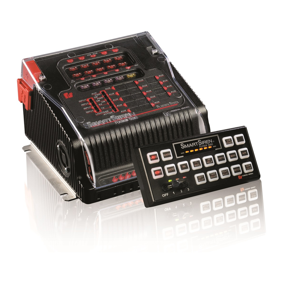
Federal Signal Corporation SSP2000B Quick Connect Manual
System wiring connections
Hide thumbs
Also See for SSP2000B:
Advertisement
Table of Contents
- 1 System Wiring Connections
- 2 Back of SSP3000B Siren Amplifier / Relay Module
- 3 FS Convergence™ NETWORK CONNECTIONS (to Serially-Controlled Devices)
- 4 Quick Connect Guide: SSP3000B/SSP2000B System LED Indicators, Fuses, and Volume Controls
- 5 Front of Siren Amplifier/Relay Module
- 6 Front of Control Pad
- 7 Back of Control Pad
- 8 External Fuses at a Glance
- Download this manual
Quick Connect Guide: SSP3000B/SSP2000B System Wiring Connections
25500152 REV. A0 1014
Back of SSP3000B Siren Amplifier / Relay Module
SERIAL PORTS: Connect
FS C
onvergenCe
up to two Federal Signal
NETWORK
serially-controlled devices.
CONNECTIONS
(to serially-
controlled devices)
–
SERIAL PORTS
6-PIN CABLE ASSY.
(P/N 17500307):
See connector detail below.
BLUE 18 AWG
BROWN
18 AWG
100 W (SSP2000B/SSP3000B)
SPEAKERS: Two are
connected in parallel
and in phase (SSP3000B).
200 W (SSP3000B ONLY)
SSP2000B has only one
speaker.
AUX. RELAY 1–10:
10 A solid-state relays 9/10
can be configured as 12 Vdc
™
out or ground out. Relays 1-8
are 12 Vdc out. The SSP2000B
has only relays 1-6 and 10.
For these two connectors
(P/N 1751541 and P/N 1751542-01)
see the enlarged detail on the right.
SM
+12V
10 8 6
4
2
+
1
2 3
4
5 6 7 8
9
7
5
3
1
P
11 1 1 1
2
3
4
1
2 3 4
AUX
PARK
AUX
INPUT
DO NOT EXCEED 5 AMPS
MAXIMUM ON HORN RING
CIRCUIT. SEE INSTALLATION
INSTRUCTIONS
RADIO: Rebroadcasts
incoming radio messages
through the siren speakers.
HORN RING: Enables the
step-through selection of
siren tones each time the
horn ring is pressed while
the control of the tone is
transferred.
RELAY CABLE ASSY.
(P/N 1751541)
10
8
6
4
2
18 AWG
PARK INPUT (BLACK):
Sends a signal to the siren
9
7
5
3
1
amplifier that:
+
•
mutes all siren tones except
Air Horn and Manual
OR
•
disables white flashing lights
when the vehicle transmission
is shifted into park or neutral.
FS C
NETWORK CONNECTION
onvergenCe
CABLE, 25 FEET LONG (P/N 1751357-02)
ETHERNET
CABLE ASSY.
(P/N 1751532)
CONTROL PAD CABLE
ASSY. (P/N 17500308)
TO -GND
Computer for the
TO +12 V CONNECTION
software configuration
ACTIVATED BY IGNITION (OR
TO +BAT IF THE IGNITION
of the siren system.
TIMER FUNCTION IS USED)
For details, see the "SmartSiren Platinum Series Installation, Maintenance,
and Service Manual" (P/N 25500151) and the "Convergence Network
Configuration Software Manual" (P/N 2562418).
S
M
ignal
CABLE ASSY. (P/N 1751542-01)
SM
SM
1
SM SM SM SM SM SM
BLACK
11 12 13 14
AUX. RELAYS
AUX. RELAYS 11-14:
2 A solid-state relays
are 12 Vdc out only.
INPUT 4 (BLUE)
RED
IGNITION INPUT (YELLOW)
IF THE IGNITION TIMER
BLACK
FUNCTION IS USED
22 AWG
INPUT 3 (PURPLE)
INPUT 2 (WHITE/YELLOW)
INPUT 1 (GRAY)
™, RELAY and INPUTS
aSter
SM
SM
SM
SM
SM
SM
8-HEAD
2
3
4
5
6
7
8
M
S
IGNAL
ASTER
6-HEAD
1
2
3
4
5
6
S
M
IGNAL
ASTER
20 AWG
INPUTS 1–2:
Apply ground
to activate.
1
2
3
4
INPUTS 3–4:
Apply 12 Vdc
INPUTS
to activate.
MICROPHONE
(P/N 258B577-03)
ACTIVE-LOW INPUTS 1-4:
Ground-activated. Can be
programmed to activate with the
control pad, installer-supplied
switches (current capacity of
100 mA each), or with the two-
position switches on the steering
wheel of the Ford Police Interceptor.
Advertisement
Table of Contents

Summary of Contents for Federal Signal Corporation SSP2000B
- Page 1 For details, see the "SmartSiren Platinum Series Installation, Maintenance, Quick Connect Guide: SSP3000B/SSP2000B System Wiring Connections and Service Manual" (P/N 25500151) and the "Convergence Network Configuration Software Manual" (P/N 2562418). RELAY CABLE ASSY. 25500152 REV. A0 1014 ™, RELAY and INPUTS...
- Page 2 Quick Connect Guide: SSP3000B/SSP2000B System LED Indicators, Fuses, and Volume Controls KEYPAD: The keypad legends in the illustration are Front of Siren Amplifier/Relay Module Front of Control Pad (SSP3000B shown) for a typical configuration. The SSP3000B kit includes additional legends. All buttons are programmable.


Need help?
Do you have a question about the SSP2000B and is the answer not in the manual?
Questions and answers