Table of Contents
Advertisement
Quick Links
Advertisement
Table of Contents

Related Manuals for AVOCOR F10 Series


Summary of Contents for AVOCOR F10 Series
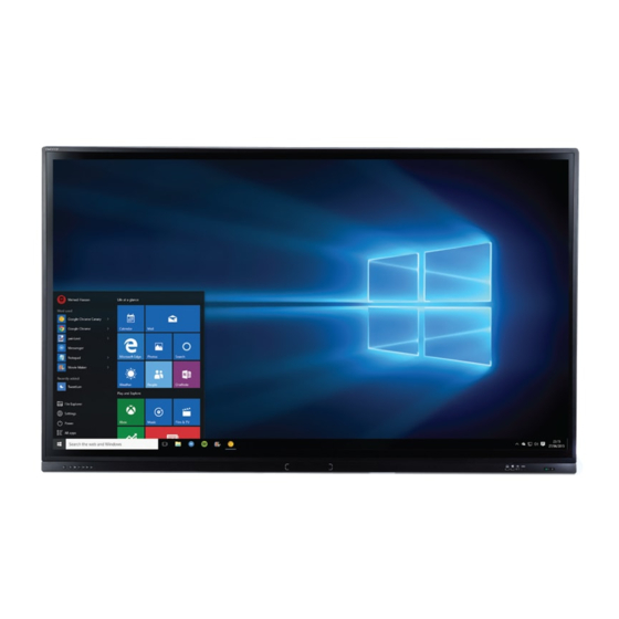
- Page 1 AVF-7510 Super-slim UHD LED Display Model AVF-7510 Installation/Operation Manual...
- Page 2 COPYRIGHT AND TRADEMARKS: © Copyright 2016. This document contains proprietary information protected by copyright, trademark and other intellectual property laws. All rights are reserved. No part of this manual may be reproduced by any mechanical, electronic or other means, in any form, without our prior written permission. The trademarks reproduced in this document and used on the products are either owned or licensed by us, or by their respective holders.
-
Page 3: Important Safety Instructions
Important Safety Instructions Before using this display, please read this user manual thoroughly to help protect against property damage and to ensure your personal safety and the safety of others. Be sure to observe the following instructions. For your safety, be sure to observe the warnings located in this manual. ... -
Page 4: Installation
Installation Don't install in a high-temperature environment. If the display is used in high-temperature or in direct sunlight, it may cause the case or other parts to become distorted or damaged, resulting in overheating or electrical shock. Don't install in a high-humidity environment. ... -
Page 5: Use
If you encounter a problem during installation, please contact your dealer for assistance. Don’t repair or open the display by yourself. Failure to do so may result in fire or electrical shock. Contact your dealer for inspection. Protect and correctly use the power cord/plug. ... -
Page 6: Cleaning
Don’t mix a new battery with a used one. Don’t mix different types of batteries together (only use the specified type). it may cause burn and injury. Cleaning If dust has collected on the power plug, removed the plug from the outlet and clean off the dust. ... -
Page 7: Warnings
Warnings Do not use the display lying flat on its back. Transport the display upright with proper packaging. Avoid placing the display face up or down. Be careful not to bump into the display. Do not send a static (non-moving) image to the display, or it may cause image ‘burn-in’ or image ... -
Page 8: Compliance Information
Compliance Information DECLARATION OF CONFORMITY: AVOCOR hereby declares that the Product's Model Number: AVF-7510 Conform with the provisions of: FCC: FCC CFR Title 47 Part 15 Subpart B Class A, CISPR 22 ANSI C63.4 ICES-003 Issue 5 1999/5/EC... - Page 9 INDUSTRY CANADA (ICES-003): CAN ICES-3 (A)/NMB-3(A) PRODUCT DISPOSAL: The Product contains small amounts of tin, lead and / or mercury. Disposal of these materials maybe regulated due to environmental considerations. DISPOSAL OF OLD ELECTRICAL AND ELECTRONIC EQUIPMENT (Applicable throughout the European Union and other European countries with separate collection programs) This symbol found on your product or on its packaging, indicates that this product should not be treated as household waste when you wish to dispose of it.
- Page 10 Notes...
-
Page 11: Table Of Contents
Table of Contents Important Safety Instructions ......................3 Safety Precautions ............................3 Installation ..............................4 Use ................................5 Cleaning ............................... 6 Warnings .............................. 7 Use ................................7 Exemptions ..............................7 Compliance Inform ation ........................8 T able of Contents ..........................11 List of Figures ............................. - Page 12 Picture Menu ..............................42 Audio Menu ..............................44 OSD Settings Menu ............................45 Setup Menu ..............................46 Advanced Setup Menu ..........................47 Communication Menu ..........................49 Information ..............................50 5 . M aintenance and Troubleshooting ..................51 Maintenance .............................. 51 Troubleshooting ............................
-
Page 13: List Of Figures
List of Figures Figure 2-1. Display Rear/ Side / Front View ........................... 19 Figure 2-2. Display Input Panel Side/Front View ........................21 Figure 2-3. Display Remote Control Unit ..........................23 Figure 3-1. Ventilation Requirements for Enclosure Mounting ................... 27 Figure 3-2. RS-232 Control System Connection ........................29 Figure 3-3. - Page 14 Notes...
-
Page 15: Introduction
1. Introduction About This Manual This Owner’s Manual describes how to install, set up and operate the AVOCOR Series LED Display. Throughout this manual, the AVOCOR Series LED Display is referred to as the “display”. Target Audience The manufacturer has prepared this manual to help installers and end users get the most out of the display. -
Page 16: Using This Manual
Using This Manual Use the following table to locate the specific information you need in this manual. If you need..Turn to page: General information about the AVOCOR Series LED Display Installation instructions First-time configuration instructions Advanced configuration instructions... -
Page 17: Description, Features And Benefits
Description, Features and Benefits The AVF-7510 is a ultra-high definition touch display that supports a full 3840x2160 @ 60 Hz resolution and can display 1.073 billion colours. They combine ultra-high resolution and unparalleled image quality with configurable I/O in a large-format display for a wide range of digital signage and control-room applications. -
Page 18: Parts List
Parts List Your display is shipped with the following items. If any items are missing or damaged, please contact your dealer or Customer Service. AVOCOR UHD LED Display Remote Control Unit and Batteries AC Power Cord Touch Stylus ... -
Page 19: Controls And Functions
2. Controls and Functions Display at a Glance Figure 2-1 shows the key display components, and the paragraphs that follow describe them. Figure 2-1. Display Rear/ Side / Front View MAIN POWER SWITCH Connects or disconnects the display panel from the AC power source. HANDLE Always use the handles and lower handlebars (AVF-6510) when carrying the display. - Page 20 KEYPAD You can use the keypad instead of the remote control unit to operate the on-screen display (OSD) controls. The keypad operates as follows: POWER Press the button to turn off/on the monitor screen. (Refer to Appendix V for detailed operations.) SOURCE Press the button to select a media source.
-
Page 21: Input Panel
Input Panel Figure 2-2 shows the display input panel. Figure 2-2. Display Input Panel Side/Front View... - Page 22 Connector RS232C In A female, 9-pin D-sub connector for interfacing with a PC or home theatre automation/control system. LAN Port An RJ-45 connector for interfacing with a PC or home theater automation/control system via a Cat 5 cable. Hub In (Touch USB) 3, 19 Two standard, Type-B USB port for connecting media sources to the display.
-
Page 23: Remote Control Unit
Remote Control Unit Figure 2-3 shows the display remote control, and Table 2-1 describes its functionality. Figure 2-3. Display Remote Control Unit... - Page 24 Table 2-1. Remote Control Button Descriptions Label Description Turns the monitor on and off. (Refer to Appendix V for detailed operations.) Selects a media source. Turns on WIN PC, and selects WIN PC input source. (Refer to Appendix V for detailed operations.) Blanks the screen.
-
Page 25: Installation
3. Installation NOTE Installation must be performed by a qualified custom video installation specialist. Remote Control To install batteries in the remote control: Press down the tab on the cover and pull the cover up. Insert the included batteries. Ensure that the polarities correctly match the markings inside the battery component. -
Page 26: Quick Setup
Connect signal sources to the display Apply power to the display Change the OSD language (optional) Perform touch screen-specific installation and configuration tasks (AVOCOR): Connect touch screen controller host computer to the display Display calibration - adjust the following for each input: Aspect ratio ... -
Page 27: Ventilation
Ventilation If you are mounting the display in an enclosure, leave sufficient space on all sides between it and surrounding objects, as shown in Figure 3-1. This allows heat to disperse, maintaining the proper operating temperature. Wall Wall Figure 3-1. Ventilation Requirements for Enclosure Mounting... -
Page 28: Mounting The Display
Mounting the Display You can mount the display on a wall. If you do decide to wall-mount the display, ensure that the wall-mount bracket is installed according to the instructions included with it. The wall must be capable of supporting a redundant weight factor three (3) times the weight of the display, or be reinforced. -
Page 29: Connecting A Control System Or Pc
Connecting a Control System or PC: RS232 Connection Use a straight-through RS-232 cable with a 9-pin male connector to connect a PC or control/ automation system (if present) to the RS-232 port on the display; see Figure 3-2. For more information about using this connection, refer to External Control on page 54. Figure 3-2. -
Page 30: Figure 3-3. Ethernet Connection
Ethernet Connection Use a standard Ethernet cable with an RJ-45 male connector to connect a PC or control/automation system (if present) to the Ethernet port on the display. For more information about using this connection, refer to External Control on page 54. Figure 3-3. -
Page 31: Connecting Source Components To The Display
Connecting Source Components to the Display Connect your video sources to the display as shown and described in the sections that follow. DisplayPort Source Connection: See Figure 3-4. Figure 3-4. DisplayPort Source Connection... -
Page 32: Figure 3-5. Hdmi Source Connections
HDMI Source Connections: See Figure 3-5. Use the HDMI inputs whenever possible. This ensures the highest video quality because the signal is carried in the digital domain throughout the entire signal path, from source component output into the display. This display supports the VESA Display Data Channel (DDC) standard. This standard NOTE provides “Plug and Play”... -
Page 33: Turning On The Power
VGA Source Connection: Connect a personal computer or other RGB source to the VGA input as shown in Figure 3-6. NOTE Refer to Supported Timings on page 69 for a list of compatible input signals. Figure 3-6. VGA Source Connections Turning on the Power Turn on your source components. -
Page 34: Changing The Osd Language
Changing the OSD Language The display OSD language is initially set to English, but can also display the menus in different languages. To change the OSD language: Press MENU. Select Basic Settings from the Main Menu. Select OSD Language from the Basic Settings Menu. Press to select the desired language and press ENTER. -
Page 35: Software Installation
Software Installation This driver is not needed for any touch functionality, but is needed in order to perform firmware upgrade. Automatic Driver Installation If the automatic driver installation starts, please allow it to run until completion in order to not disrupt the automatic process. - Page 36 Clicking on the pop-up ballo would show In the Device Manager, the view would be (again, use View --> Devices by connection): In this case, please proceed with Manual Driver Insatllation. Manual Driver Installation If the automatic driver installation failed for any of the reasons listed above, or if you would like to install the driver without having a FlatFrog touch device connected to the computer, the driver can be installed manually.
- Page 37 Select "Browse my computer for driver software" and select the extracted folder from step 1 and follow the instructions. If step 4 was unsuccessful, then Windows failed to automatically associate the driver with the device. Choose "Let me pick from a list if device drivers on my computer" in step 4, scroll all the way down to "Universal Serial Bus devices"...
- Page 38 Select the WinUsb device driver, and click Next. (If the WinUsb device driver is not in the list, please follow the steps under "Manual Driver Installation - Device Not Connected" first). Manual Driver Installation - Device Not Connected Extract the firmware upgrade .zip file (right-click --> Extract all...) to the Desktop. Navigate to the "support"...
-
Page 39: 4. Operation
4. Operation Using the On-Screen Menus To display the on-screen menus, press MENU on the remote control (Figure 2-3) or built-in keypad (Figure 2-1). To select a sub-menu, use the buttons to highlight it. Then, press to enter that sub-menu. To select a menu item, use the buttons to highlight it. -
Page 40: Figure 4-1. Osd Menu Structure
Main Menu SubMenu Value Horizontal 0~100 Vertical 0~100 Transparency Off; 1~4 OSD Settings OSD Timeout 5s; 10s; 20s; 30s; 60s English, French, German, Dutch, Hungarian, Slovenian, Language Serbian, Croatian, Danish Splash Screen On; Off Auto Adjustment H.Position 0~100 V.Position 0~100 Phase 0~100 Clock... -
Page 41: Input Menu
Input Menu This menu is used for selecting the main input source (Main) and up to three Picture-in-Picture input sources (Sub1, Sub2 and Sub3). Up to four sources can be displayed at the same time. Main Input Select the main input source Options: VGA, DisplayPort, HDMI1, HDMI2, HDMI3, HDMI4, OPS, Front HDMI, PC Auto Scan Select whether the display will automatically scan for a main input source... -
Page 42: Picture Menu
Swap Swap the main input source with the primary PiP source Note: This function is only available when PiP Mode is set to PiP, PbP, 3Window or 4Window Rename Source Rename the input source. Press ENTER to sele ct the input source you want to rename. Using ▲ or ▼ to change the character and ... - Page 43 Saturation Adjust the brilliance and brightness. Press or to select the desired level, and then press ENTER. Range: 0~100; Default: 50 Note: This function is not available when displaying PC or graphics sources Backlight Increase or decrease the intensity of the LCD backlight. Press or...
-
Page 44: Audio Menu
Blue Offset Set Colour Temperature to “User Mode” in order to adjust this setting. Range: 0~100; Default: 50 Audio Menu This menu is used for adjusting volume settings. Volume Adjust the sound. Press or to select the desired level, and then press ENTER. -
Page 45: Osd Settings Menu
OSD Settings Menu This menu is used to make initial set-up adjustments to the OSD (On-Screen Display) menu and other on-screen messages. Horizontal Adjust the horizontal position of the OSD menu. Press or to select the desired level, and then press ENTER. Range: 0~100;... -
Page 46: Setup Menu
Setup Menu Auto Adjustment Force the display to reacquire and lock to the input signal (VGA source only). This is useful when the signal quality is marginal. Note: This feature does not continually reacquire the signal. Options: No, Yes; Default: No H. -
Page 47: Advanced Setup Menu
Advanced Setup Menu Smart Light Control Enable dynamic contrast (DCR) or ambient light sensor Options: Off, DCR, Light Sensor; Default: Off IRFM Create slight frame motion to help avoid image retention Options: On, Off; Default: Off Noise Reduction Reduce random noise in the video content Options: Off, Low, Medium, High;... - Page 48 Wake Up from Sleep By default, the display will enter power saving (Sleep Mode) if no signal is received for 5 minutes. Normally, the RS-232, DisplayPort, and HDMI inputs are inactive in Sleep Mode, to save power. To change the behavior of Sleep Mode, change the “Wake up from Sleep” setting in the “Adv. Setup” menu. VGA Only (default) –...
-
Page 49: Communication Menu
Communication Menu This menu configures the display’s RS232 and Ethernet communication ports. Baud Rate Select the baud rate of the display’s RS232 port Options: 115200, 38400, 19200, 9600 Default: 19200 Enable Network Enable the display’s built-in Ethernet port Options: No, Yes Default: No IP Address Settings Enable Dynamic IP mode or set the static IP address of the display’s Ethernet... -
Page 50: Information
Network Settings To assign an IP address to your display, access the IP Address Settings Menu in the Communication Menu. Consult your system administrator if you do not know how to configure the parameters shown in the menu. The default settings are shown below. Item Setting DHCP... -
Page 51: 5. Maintenance And Troubleshooting
Table 5-1 provides some general guidelines for troubleshooting problems you may encounter with the AVOCOR Series LED Display. If the suggested solutions fail to resolve the problem or if you encounter an issue not described here, please contact your dealer. - Page 52 Table 5-1. Troubleshooting Chart (continued) Symptom Possible Cause(s) Solution The display is jittery or unstable. Poor-quality or improperly Ensure that the source is properly connected source. connected and of adequate quality for detection. Correct at the source. The horizontal or vertical scan frequency of the input signal may be out of range for the display.
- Page 53 Should you require assistance with a suspected hardware fault, please contact the support line below. You will require your unit serial number. The operator will attempt to diagnose any fault and will take action as appropriate. UK Warranty Support US Warranty Support Tel. 01276 804 65 Tel. 858-266-8363 service@avocor.co.uk service@avocor.com...
-
Page 54: External Control
6. External Control In addition to using the display keypad or remote control unit, you can control the display using a serial (RS- 232) link to send ASCII commands and receive responses to those commands. You also use discrete infrared (IR) control codes to program a third-party remote control unit. For more information, refer to Using Discrete IR Codes on page 64. -
Page 55: Command And Response Examples
Command and Response Examples Here are some examples of serial commands and their responses: Table 6-1. Serial Command/ Response Examples Description Command sent to LCD Panel Response Received from LCD Panel Turn LCD panel power off. 07 01 02 50 4F 57 00 08 07 01 00 50 4F 57 00 08 Turn LCD panel power on. - Page 56 Value Reply Main Item Control Item Type Content (DEC) (DEC) (HEX) 0~100 0~100 Saturation 53 41 54 Noise Reduction: Off Noise Reduction: 4E 4F 52 Noise Reduction: Medium Noise Reduction: High MEMC: Off 4D 45 4D MEMC: Low (AVF-6510 MEMC: Medium only) MEMC: High Red Gain (mapping...
- Page 57 Value Reply Main Item Control Item Type Content (DEC) (DEC) (HEX) HDMI 4 DisplayPort IPC/OPS 50 49 4E HDMI 5 (Front Panel) Media Player PIP Source (Win/Android) Selection Select the input (refer to (refer source of sub 50 49 4F PIN) to PIN) window 2 (refer to...
- Page 58 (HEX) FREEZE Key MUTE Key AUTO Key VOLUME+ Key VOLUME- Key 52 43 55 Blank screen MediaPlayer / Win10 Avocor LowBlue Bright- Key Avocor LowBlue Bright+ Key Reset all 41 4C 4C Un-lock keys 4B 4C 43 Other Control Lock keys...
- Page 59 Value Reply Main Item Control Item Type Content (DEC) (DEC) (HEX) Internal Speaker Off 49 4E 53 Internal Speaker On Audio Mute Off 4D 55 54 Mute On User Sport Scheme Game 53 43 4D Selection Cinema Vivid Set VGA_ONLY EcoMode 57 46 53 VGA_DIGITAL_RS232...
- Page 60 Value Reply Main Item Control Item Type Content (DEC) (DEC) (HEX) Wednesday Alarm Disable Thursday Alarm Disable 41 45 46 Friday Alarm Disable Saturday Alarm Disable 0~23 0~23 Monday On Hour 4E 4E 48 0~59 0~59 Monday On Minute 4E 4E 4D 0~23 0~23 Monday Off Hour...
- Page 61 Value Reply Main Item Control Item Type Content (DEC) (DEC) (HEX) Main Auto Scan 41 54 53 Multi IRFM 49 52 46 Smart Light 53 4C 43 Control Light Sensor Power LED 4C 45 44 DP 1.1 DisplayPort 44 50 4D Mode Other Control DP 1.2...
- Page 62 Value Reply Main Item Control Item Type Content (DEC) (DEC) (HEX) Transpare-ncy OSD Transparency 4F 53 54 H Position 0~100 0~100 OSD H Position 4F 53 48 V Position 0~100 0~100 OSD V Position 4F 53 56 English French German Dutch 4F 53 4C Hungarian...
- Page 63 Value Reply Main Item Control Item Type Content (DEC) (DEC) (HEX) 0~255 0~255 Gateway 2 47 57 32 0~255 0~255 Gateway 3 47 57 33 0~255 0~255 Gateway 4 47 57 34 0~255 0~255 DNS Address 1 46 44 31 0~255 0~255 DNS Address 2...
-
Page 64: Using Discrete Ir Codes
Using Discrete IR Codes The display accepts commands in the form of infrared (IR) signals that conform to the NEC protocol. Each display remote control button has an IR control code associated with it. You can use these codes to program a third-party, “universal” remote control unit to work with the display. These third-party products usually come with a computer software application for this purpose. -
Page 65: Ir Control Code List
IR Control Code List Table 6-3 lists the IR control codes for the display. Table 6-3. Infrared (IR) Control Codes Customer Code Data Code Function 40AF 04FB ---------- 40AF 1CE3 POWER 40AF 07F8 SOURCE 40AF 08F7 ---------- 40AF 09F6 WIN PC 40AF 0AF5 BLANK... - Page 66 Notes:...
-
Page 67: Specifications
7. Specifications Table 7-1 lists the signal types supported by each input on the display. AVF-7510 PANEL Diagonal Size (Inch) 75” Backlight Edge LED Aspect Ratio 16:9 Input Resolution 3840 x 2160 @ 60 Hz Response Time 8 (ms) Brightness 410 (cd/m Contrast Ratio 1200:1... - Page 68 OSD FUNCTIONS OSD Languages English, German, Dutch, French, Danish, Slovenian, Hungarian, Serbian, Croatian Source Auto Detect Function POWER Power Supply AC100-240V (Worldwide), Max 3.5 A, 50/60Hz Maximum Power 320 W Consumption Standby ≦0.5 W ENVIRONMENTAL Operating Temperature 5 °C ~ 40 °C Storage Temperature -20 °C ~ 60 °C Humidity...
-
Page 69: Supported Timings
Supported Timings Table 7-2 lists the signal types supported by each input on the display. Table 7-2. Supported Timings By Input Dot clock Timing fH (kHz) fV (Hz) HDMI DisplayPort (MHz) 31.469 59.94 25.175 37.861 72.809 31.5 VGA 640x480 37.5 31.5 43.269 85.008... - Page 70 Dot clock Timing fH (kHz) fV (Hz) HDMI DisplayPort (MHz) 1080i 28.13 74.25 1920x1080 33.716 59.94 74.176 33.75 74.25 74.25 28.125 74.25 33.75 74.25 1080p 1920x1080 56.25 148.5 67.433 59.94 148.352 67.5 148.5 56.25 67.5 4K2K 3840x2160 110.5 49.977 112.5 133.313 59.997 533.25...
-
Page 71: Overall Dimensions
Overall Dimensions Figure 7-1 shows the display dimensions ofAVF-7510 (all dimensions are millimetres). Figure 7-1. AVF-7510 Display Dimensions... - Page 72 Overall Dimensions Figure 7-1 shows the display dimensions of AVF-7510 (all dimensions are in inches). Figure 7-1. AVF-7510 Display Dimensions...
- Page 73 Notes:...
-
Page 74: Appendix I: Moving And Carrying Notice
Appendix I: Moving and Carrying Notice Moving the Display: Moving the display requires at least two people. Attempting to move the display with one person may result in dropping the display and/or serious injury. When moving a display in its shipping carton, lift the carton using the white handles. -
Page 75: Appendix Ii: Installing A Wall Mount
Appendix II: Installing a Wall Mount Before installing, please make sure the wall is strong enough to hold the necessary weight of the display and the mount. Step1. Keep the display facing the ground and place it on a flat object. Step2. -
Page 76: Appendix Iii: Installing An Ops Module
Appendix III: Installing an OPS Module Follow the steps below to install an OPS module. Step1. Use a screw driver to unscrew the OPS slot cover on the display input panel. Do not lose the screws that are removed. Step2. Install the OPS module by sliding it into the .OPS slot until you hear a click, indicating the module is securely inserted. -
Page 77: Appendix Iv: Wall Mount Safety Notes
Appendix IV: Wall Mount Safety Notes... -
Page 79: Appendix V: Power/ Pc Key Operations
Appendix V: Power/ PC Key Operations When current input is WIN PC: When current input is NOT WIN PC: When Win10 PC Power Mode is set to Auto or Manual, pressing the button once will turn on When Win10 PC Power Mode is set to Auto or ... -
Page 80: Appendix Vi: Ethernet Remote Control Settings
Appendix VI: Ethernet Remote Control Settings The device can be configured by opening a browser and connecting to web server directly. Use the browser to configure the demo board. Connect the browswer to the IP address of NET2UART module, and the Login window will pop up as follows. Default IP 192.168.2.1 Default ID... - Page 81 System IP Configuration Network Status Load Default Setting...
- Page 82 Firmware Update Boot Loader Upgrade...
-
Page 83: Tcp Mode
TCP Mode Telnet Server/Client Set the device to be a Telnet Server or Client. Port Number When in Server mode, assign the port number used to connect remotely. When in Client mode, assign the port number for the device to connect to the remote site. Remote Server IP Address When in Client mode, the device will connect to the remote server with the IP address set here. -
Page 84: Udp Mode
UDP Mode Status When TCP mode is set as Server mode or Client mode, the UDP mode would be disabled automatically, and vice versa. Local Port Assign the port number here to allow the device to open for the remote site to send data via UDP. The IP address of the remote site must be set in the Remote Address table, or NET2UART will ignore its data. -
Page 85: Uart
UART Mode Select the UART interface. Baud rate Select the baud rate of UART interface. Character Bits Select the number of character bits of UART interface. Parity Type Select the parity type of UART interface. Stop Bit Select the stop bit type of UART interface. Hardware Flow Control Select the flow control type of UART interface. -
Page 86: Smtp
Delimiter Character 1 & 2: Set Character 1 and/or Character 2 to be the delimiter. Once the delimiter is active, NET2UART would monitor all data received from UART. All data received from UART will be stored in NET2UART internal buffer first, and will only be sent to Ethernet once the delimiter is detected. -
Page 87: Reset Device
Reset Device Reset NET2UART module.
Need help?
Do you have a question about the F10 Series and is the answer not in the manual?
Questions and answers