Table of Contents
Advertisement
Technical Manual
Of
Intel Cedar Trail Series CPU
& NM10 Chipset
Based
3.5'' SBC
NO.G03-NF36-F
Revision: 5.0
Release date: May 31, 2013
Trademark:
* Specifications and Information contained in this documentation are furnished for information use only, and are
subject to change at any time without notice, and should not be construed as a commitment by manufacturer.
Advertisement
Table of Contents

Subscribe to Our Youtube Channel
Related Manuals for JETWAY NF36-2600


Summary of Contents for JETWAY NF36-2600
- Page 1 Technical Manual Intel Cedar Trail Series CPU & NM10 Chipset Based 3.5’’ SBC NO.G03-NF36-F Revision: 5.0 Release date: May 31, 2013 Trademark: * Specifications and Information contained in this documentation are furnished for information use only, and are subject to change at any time without notice, and should not be construed as a commitment by manufacturer.
- Page 2 Environmental Protection Announcement Do not dispose this electronic device into the trash while discarding. To minimize pollution and ensure environment protection of mother earth, please recycle.
-
Page 3: Table Of Contents
TABLE OF CONTENT ENVIRONMENTAL SAFETY INSTRUCTION................iv USER’S NOTICE ........................v MANUAL REVISION INFORMATION ..................v ITEM CHECKLIST ........................v CHAPTER 1 INTRODUCTION OF THE MOTHERBOARD FEATURE OF MOTHERBOARD................1 SPECIFICATION ......................2 LAYOUT DIAGRAM....................3 CHAPTER 2 HARDWARE INSTALLATION JUMPER SETTING ..................... -
Page 4: Environmental Safety Instruction
Environmental Safety Instruction Avoid the dusty, humidity and temperature extremes. Do not place the product in any area where it may become wet. 0 to 60 centigrade is the suitable temperature. (The figure comes from the request of the main chipset) Generally speaking, dramatic changes in temperature may lead to contact malfunction and crackles due to constant thermal expansion and contraction from the welding spots’... -
Page 5: User's Notice
USER’S NOTICE COPYRIGHT OF THIS MANUAL BELONGS TO THE MANUFACTURER. NO PART OF THIS MANUAL, INCLUDING THE PRODUCTS AND SOFTWARE DESCRIBED IN IT MAY BE REPRODUCED, TRANSMITTED OR TRANSLATED INTO ANY LANGUAGE IN ANY FORM OR BY ANY MEANS WITHOUT WRITTEN PERMISSION OF THE MANUFACTURER. -
Page 6: Chapter 1 Introduction Of The Motherboard Feature Of Motherboard
Onboard Intel Cedar Trail Processor + NM10 Chipset, with low power consumption never denies high performance Support SODIMM DDRIII 800Single Channel, up to 2GB(for NF36-2600 Series) Support SODIMM DDRIII 800/1066 Single Channel, up to 4GB (for NF36-2800 & NF36-2550 Series) -
Page 7: Specification
3.5”SBC 6 layers; PCB size: 14.8x 10.2 cm Design ® Intel NM10 Express chipset Chipset ® Intel Cedar Trail M-N2600 / 1.6GHz (for NF36-2600 series) ® Embedded CPU Intel Cedar Trail M-N2800 /1.86GHz(for NF36-2800 series) ® Intel Cedar Trail D-D2550/ 1.86GHz(for NF36-2550 series) -
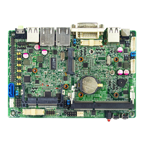
Page 8: Layout Diagram
Audio Line out connector x1 9-pin USB 2.0 header x1 (Expansible to 2* USB 2.0 ports) Internal I/O 4pin USB 2.0 header x1 (Expansible to 1*USB 2.0 port) Front panel audio header x1 SPDIF _out header x1 CIR header x1 SM_BUS header x1 Front panel header x1 SATAII port &... - Page 9 Internal Diagram: INVERTER2 SM_BUS Header INVERTER1 DC 12V Power-in Power Switch Button Connector Reset Button USB 2.0 Ports SODIMM Slot LVDS2 Header DVI-I Port CPUFAN1 Header Mini PCIE slot Front Panel Header RJ-45 LAN Port CIR Header RJ-45 LAN Port SPDIF Out CFast Card Slot Header...
-
Page 10: Jumper Position
Jumper Position: JBAT1 COPEN1 JCOMP1 JCOMP3 JCOMP4 JCOMP2... - Page 11 Jumper Jumper Name Description JBAT1 CMOS RAM Clear Function Setting 3-Pin Block LVDS1 VCC 5V/3.3V Select 3-Pin Block INVERTER1 VCC 12V/5V Select 3-Pin Block LVDS2 VCC 5V/3.3V Select 3-Pin Block INVERTER2 VCC 12V/5V Select 3-Pin Block JCOMP1 COM1 Header Pin9 Function Select 6-Pin Block JCOMP2 COM2 Header Pin9 Function Select...
- Page 12 Headers Header Name Description AUDIO1 Front panel audio header 9-pin block SPDIF SPDIF out header 2-pin block USB3 USB header 9-pin block USB4 USB header 4-pin block COM1/COM2/ Serial port headers 9-pin block COM3/COM4 TX-RXCOM1 RS422/485 header 4-pin block GPIO1 GPIO header 10-pin block JW_FP1...
-
Page 13: Jumper Setting
Chapter 2 Hardware Installation 2-1 Jumper Setting (1) JBAT1 (3-pin): Clear CMOS JBAT1 1-2 closed: Normal; 2-3 closed : Clear CMOS (2) JP1 (3-pin): LVDS1 VCC 5V/3.3V Function Setting 1-2 closed: LVDS1 VCC 5V(default); 2-3 closed : LVDS1 VCC 3.3V... - Page 14 (3) JP2 (3-pin): INVERTER1 VCC 12V/5V Select 1-2 closed:Inverter1 VCC=12V (default); 2-3 closed:Inverter1 VCC=5V (4) JP3 (3-pin): LVDS2 VCC 5V/3.3V Function Setting 1-2 closed: LVDS2 VCC 5V(default); 2-3 closed : LVDS2 VCC 3.3V...
- Page 15 (5) JP4 (3-pin): INVERTER2 VCC 12V/5V Select 1-2 closed:Inverter2 VCC=12V (default); 2-3 closed:Inverter2 VCC=5V (6) JCOMP1 (6-pin): COM1 Pin9 Function Select JCOMP1 1-2 closed: RS232; 3-4 closed : +12V; 5-6 closed : +5V...
- Page 16 (7) JCOMP2 (6-pin): COM2 Pin9 Function Select JCOMP2 1-2 closed: RS232; 3-4 closed : +12V; 5-6 closed : +5V (8) JCOMP3 (6-pin): COM3 Pin9 Function Select JCOMP3 1-2 closed: RS232; 3-4 closed : +12V; 5-6 closed : +5V...
- Page 17 (9) JCOMP4 (6-pin): COM4 Pin9 Function Select JCOMP4 1-2 closed: RS232; 3-4 closed : +12V; 5-6 closed : +5V (10) JP5 (6-pin): COM4 RS232/485/422 Function Select 1-2 closed: RS232; 3-4 closed : RS485; 5-6 closed : RS422...
- Page 18 (11)COPEN (2-pin): Case Open Message Display function select COPEN 1-2 Open: Normal; 1-2 Short: Case Open Case Open Display Function Pin 1-2 shorted: Case open display function enabled. In this case if you case is removed, next time when you restart your computer a message will be displayed onscreen to inform you of this.
-
Page 19: Connectors And Headers
Connectors and Headers 2-2-1 Connectors (1) Rear I/O Connectors RJ-45 LAN Ports DVI-I Port Line-Out DC12V Connector Power-in Connector USB 2.0 Ports USB 2.0 Ports (2) SATAII Port connector: SATA1 SATA1 connector is an SATAII connector that supports SATA hard disk. Pin No. -
Page 20: Headers
(3)SATA Power Connector (4-pin): PWOUT1 Pin 1 2-2-2 Headers (1) Front panel audio (9-pin): AUDIO1 AUDIO1 Pin 1 Line-Out, MIC Header... - Page 21 (2) HDMI-SPDIF Out header (2-pin): SPDIF SPDIF Pin1 HDMI_SPDIF Header (3) USB 2.0 Port Header (9-pin): USB3 Pin 2 Pin 1...
- Page 22 (4) USB 2.0 Port Header (4-pin): USB4 Pin 1 (5) Serial Port Header (9-pin): COM1,COM2, COM3, COM4 Pin6 Pin5 Pin1 Serial Port Header 9-pin Block...
- Page 23 (6) RS422/485 Header (4-pin): TX_RXCOM Pin 1 TX-RXCOM Header (7) GPIO Header (10-pin): GPIO1 Pin2 Pin10 Pin1 Pin9 GPIO Header...
- Page 24 (8) Front Panel Header (9-pin): JW-FP1 Pin 2 Pin 1 (9)FAN Header (3-pin): CPUFAN1 Pin1 +12V Fan Power Fan Speed Dec...
- Page 25 (10)CIR Header (4-pin): CIR Pin 1 (11)SM_BUS Header (4-pin): SM_BUS Pin 1...
- Page 26 (12) LVDS Inverter Header (8-pin): INVERTER1 Pin No. Definition Backlight Enable Backlight Duty PVCC PVCC Pin 1 Backlight +SW Backlight -SW INVERTER1 (13) LVDS Inverter Headers (8-pin):INVERTER2 Pin No. Definition Backlight Enable Backlight Duty/NC PVCC PVCC Pin 1 Backlight+ SW /NC Backlight- SW/NC INVERTER2...
- Page 27 (14)24-bit dual channel LVDS Header (30-pin): LVDS1 Pin2 Pin 1 Pin 30 Pin 29 LVDS1 Header Pin NO. Pin Define Pin NO. Pin Define Pin 1 LVDSB_DATAN3 Pin 2 LVDSB_DATAP3 Pin 3 LVDS_CLKBN Pin 4 LVDS_CLKBP Pin 5 LVDSB_DATAN2 Pin 6 LVDSB_DATAP2 Pin 7 LVDSB_DATAN1...
- Page 28 (15) 18-bit /24-bit single channel LVDS Header (30-pin): LVDS2 Pin2 Pin 1 Pin 30 Pin 29 LVDS1 Header Pin NO. Pin Define Pin NO. Pin Define Pin 1 Pin 2 Pin 3 Pin 4 Pin 5 Pin 6 Pin 7 Pin 8 Pin 9 Pin 10...
-
Page 29: Chapter 3 Introducing Bios
Chapter 3 Introducing BIOS Notice! The BIOS options in this manual are for reference only. Different configurations may lead to difference in BIOS screen and BIOS screens in manuals are usually the first BIOS version when the board is released and may be different from your purchased motherboard. Users are welcome to download the latest BIOS version form our official website. -
Page 30: Bios Menu Screen
BIOS Menu Screen The following diagram show a general BIOS menu screen: Menu Bar General Help Items Menu Items Current Setting Value Function Keys Instruction Function Keys In the above BIOS Setup main menu, you can see several options. We will explain these options step by step in the following pages of this chapter, but let us first see a short description of the function keys you may use here:... -
Page 31: Getting Help
Press←→ (left, right) to select screen; Press ↑↓ (up, down) to choose the item you want to confirm or to modify in the main menu. Press <Enter> to select. Press <+>/<–> key when you want to modify the BIOS parameters for the active option. -
Page 32: Manu Bar
3-5 Menu Bar There are six menu bars on top of BIOS screen: Main To change system basic configuration Advanced To change system advanced configuration Chipset To change chipset configuration Boot To change boot settings Security Password settings Save & Exit Save setting, loading and exit options. - Page 33 System Date Set the date. Please use [TAB] to switch between data elements. System Time Set the time. Please use [TAB] to switch between time elements.
-
Page 34: Advanced Menu
3-7 Advanced Menu Lagacy OpROM Support Launch LAN1 OpROM/Launch LAN2 PXE OpROM Use this item to enable or disable boot option for legacy network devices. Launch Storage OpROM Use this item to enable or disable boot option for legacy mass storage devices with option ROM. - Page 35 Use this item to enable or disable PCI Express root port 1. Onboard LAN 2 Controller Use this item to enable or disable Mini- PCIE control. ERP Support Use this item to enable or disable ERP function for this board. This item should be set as [Disabled] if you wish to have Active All Wakeup Function.
- Page 36 Limit CPUID Maximum The optional settings are: [Disabled]; [Enabled]. This item should be set as [Disabled] for Windows XP. ► SATA Configuration SATA Controller(s) The optional settings are: [Disabled]; [Enabled]. Configure SATA as The optional settings are: [IDE]; [AHCI]. ► USB Configuration Legacy USB Support The optional settings are: [Auto];...
- Page 37 ► Super I/O Configuration CIR Controller The optional settings are: [Disabled]; [Enabled]. Case Open Detect To detect if the case has bee opened or not.The optional settings are: [Enabled]; [Disabled]. ► PC Health Status Press [Enter] to view hardware health status and make settings SmartFAN Configuration.
- Page 38 Serial Port Use this item to enable or disable serial port (COM). Change Settings Use this item to select an optimal setting for super IO device. ► COM4 Port Configuration Press [Enter] to make settings for the following items: Serial Port Use this item to enable or disable serial port (COM).
- Page 39 The optional settings are: [Second]; [Minute]. ► Shutdown Temperature Configuration Use this item to select system shutdown temperature. ► PPM Configuration Use this item to set PPM configuration parameters. Press [Enter] to make settings for the following sub-items: EIST Use this item to enable or disable Intel Speed Step. CPU C-State Report Use this item to enable or disable CPUC-state report to OS.
-
Page 40: Chipset Menu
3-8 Chipset Menu ► Host Bridge Press [Enter] to make settings for Intel IGD Configuration: Internal Graphics Use this item to keep IGD enabled based on the setup options. The optional settings are: [Disabled]; [Auto]. IGFX-Boot Type Use this item to set the video device which will be activated during POST. This has... - Page 41 no effect if external graphics presents. The optional settings are: [VBIOS Default]; [DVI→CRT]; [DVI/HDMI]; [LVDS2]; [LVDS1]; [HDMI+LVDS1]; [CRT+LVDS2]; [CRT+LVDS1]. LCD Panel Type: The optional settings are: [1024 x 600]; [800 x 600]; [1024 x 768 18bit]; [1366 x 768]; [1280 x 800]. *Note: LCD Panel Type item is only available when IGFX-Boot Type is set as [LVDS2], [CRT+LVDS2].
- Page 42 Active LFP The optional settings are: [Disable LVDS]; [Enable LVDS]. ► South Bridge Azalia Controller The optional settings are: [Enabled]; [Disabled]. UHCI #1 (Ports 0 and 1)/ UHCI #2 (Ports 2 and 3)/UHCI #3 (Ports 4 and 5)/UHCI #4 (Ports 6 and 7) Use this item to control the USB UHCI (USB 1.1) functions.
-
Page 43: Boot Menu
3-9 Boot Menu Setup Prompt Timeout Use this item to set number of seconds to wait for setup activation key. Bootup Numlock State Use this item to select keyboard numlock state. The optional settings are: [On]; [Off]. Quiet Boot The optional settings are: [Enabled]; [Disabled]. Gate A20 Active... -
Page 44: Security Menu
The optional settings are: [Upon Request]; [Always]. Option ROM Message Use this item to set display mode for option ROM. The optional settings are: [Force BIOS]; [Keep Current]. Interrupt 19 Capture The optional settings are: [Enabled]; [Disabled]. 3-10 Security Menu... -
Page 45: Save & Exit Menu
Security menu allow users to change administrator password and user password settings. 3-11 Save & Exit Menu Save Changes and Reset This item allows user to reset the system after saving the changes. Discard changes and Reset This item allows user to reset the system without saving any changes. - Page 46 Restore Defaults Use this item to restore /Load default values for all the setup options. Save as User Defaults Use this item to save the changes done so far as user defaults. Restore User Defaults Use this item to restore defaults to all the setup options.
Need help?
Do you have a question about the NF36-2600 and is the answer not in the manual?
Questions and answers