Table of Contents
Advertisement
Quick Links
623DM/623DMP/623DMW
USER'S MANUAL
M/B For Socket 370 Pentium
III
Processor
NO. G03-623DM
Rev:1.0
Release date: September 2003
Trademark:
* Specifications and Information contained in this documentation are furnished for information use only, and are
subject to change at any time without notice, and should not be construed as a commitment by manufacturer.
Advertisement
Table of Contents

Related Manuals for JETWAY 623DM


Summary of Contents for JETWAY 623DM
- Page 1 USER'S MANUAL M/B For Socket 370 Pentium Processor NO. G03-623DM Rev:1.0 Release date: September 2003 Trademark: * Specifications and Information contained in this documentation are furnished for information use only, and are subject to change at any time without notice, and should not be construed as a commitment by manufacturer.
-
Page 2: Table Of Contents
TABLE OF CONTENT USER’S NOTICE......................ii MANUAL REVISION INFORMATION................ii THERMAL SOLUTIONS.....................ii CHAPTER 1 INTRODUCTION OF MOTHERBOARD 1-1 FEATURE OF MOTHERBOARD.................1 1-2 SPECIFICATION....................2 1-3 PERFORMANCE LIST...................3 1-4 LAYOUT DIAGRAM & JUMPER SETTING............4 CHAPTER 2 HARDWARE INSTALLATION 2-1 HARDWARE INSTALLATION STEPS..............6 2-2 CHECKING MOTHERBOARD'S JUMPER SETTING........6 2-3 INSTALL CPU......................7 2-3-1 GLOSSARY....................7 2-3-2 SETTING CPU BUS CLOCK &... -
Page 3: User's Notice
USER’S NOTICE COPYRIGHT OF THIS MANUAL BELONGS TO MANUFACTURER. NO PART OF THIS MANUAL, INCLUDING THE PRODUCTS AND SOFTWARE DESCRIBED IN IT MAY BE REPRODUCED, TRANSMITTED OR TRANSLATED INTO ANY LANGUAGE IN ANY FORM OR BY ANY MEANS WITHOUT WRITTEN PERMISSION OF MANUFACTURER. -
Page 4: Feature Of Motherboard
Introduction of 623DM/623DMP/623DMW Motherboard 1-1 Feature of motherboard The 623DM/623DMP/623DMW motherboard is design for use Intel’s new generation Pentium processors, which utilize the Socket 370 design and the memory size expandable to 2GB. This motherboard uses the newest VIA VT8623 (CLE266) SMA (Share Memory Architecture) North bridge chipset and VT8235 south bridge chipset. -
Page 5: Specification
1-2 Specification Spec Description Micro ATX form factor 4 layers PCB size: 24.4x19.0cm Design VIA VT8623 SMA (Share Memory Architecture) North Bridge Chipset VIA VT8235 South Bridge ICS 950908 Clock Generator Clock Generator Support 66/100/133MHz system Bus Clock (CPU Bus Clock) ... -
Page 6: Performance List
1-3 Performance List The following performance data list is the testing result of some popular benchmark testing programs. These data are just referred by users, and there is no responsibility for different testing data values gotten by users (the different Hardware & Software configuration will result in different benchmark testing results.) Intel Pentium III ... -
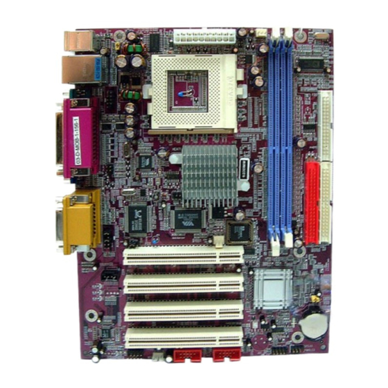
Page 7: Layout Diagram & Jumper Setting
1-4 Layout Diagram & Jumper Setting GAME/MIDI PORT PRINT PS/2 MOUSE PS/2 Keyboard LINE-IN COM1 LINE-OUT VIA VT1622A Chip K/B Power ON Jumper ATX Power Connector (JP1) CPU FAN PS2 KB/Mouse Port USB Port/ LAN Connector 370 CPU Socket DIMM Socket X2 COM2 Connector TV OUT Connector Floppy Connector... -
Page 8: Chapter 2 Hardware Installation
Keyboard Power ON Function Setting 3-pin Block USB Power On Function Setting 3-pin Block CMOS RAM Clear Function Setting 3-pin Block Connectors Connector Name Description Page ATXPWR ATX Power Connector 20-pin Block p.13 KB/MS1 PS/2 Mouse & PS/2 Keyboard Connector 6-pin Female p.13 UL_B1... -
Page 9: Hardware Installation Steps
2-1 Hardware installation Steps Before using your computer, you had better complete the following steps: Check motherboard jumper setting Install CPU and Fan Install System Memory (DIMM) Install Expansion cards Connect IDE and Floppy cables, Front Panel /Back Panel cable Connect ATX Power cable Power-On and Load Standard Default Reboot... -
Page 10: Glossary
Turn off the system and unplug the AC power Remove ATX power cable from ATX power connector Locate JP5 and short pins 2-3 for a few seconds Return JP5 to its normal setting by shorting pins 1-2 Connect ATX power cable back to ATX power connector Note: When should clear CMOS 1. -
Page 11: Setting Cpu Bus Clock & Memory Clock Jumper
CPU L2 Cache - The flash memory inside the CPU, normally Pentium III CPU has 256K or above, while Celeron CPU will have 128K. The way to recognize the specification of CPU from the packing Pentium III 370 pins FC-PGA On the surface of the CPU as shown on the right picture, under the word of “PENTIUM III”... -
Page 12: Overclock Running
WARNING! Be sure that there is sufficient air circulation across the processor’s heatsink and CPU cooling FAN is working correctly, otherwise it may cause the processor and motherboard overheat and damage, you may install an auxiliary cooling FAN, if necessary. To install a CPU, first turn off your system and remove its cover. -
Page 13: Install Memory
** Current Host/PCI Clock is 133/133 MHz ** Menu Level > Host/PCI Clock at Next Boot is 133/33MHz ** Current DRAM Clock is 133MHz ** DRAM Clock at Next Boot is 133MHz +2.5V Select 2.55V Move Enter:Select Item +/-/PU/PD:Value F10:Save ESC:Exit F1:General Help F5:Previous Values F6:Optimized Defaults F7:Standard Defaults... -
Page 14: Expansion Cards
Figure 2-4 NOTE! When you install DIMM module fully into the DIMM socket the eject tab should be locked into the DIMM module very firmly and fit into its indention on both sides. WARNING! For the DDR SDRAM CLOCK is set at 133MHz, use only DDR266-compliant DDR Modules. -
Page 15: Interrupt Request Table For This Motherboard
System Timer Keyboard Controller Programmable Interrupt Communications Port (COM2) Communications Port (COM1) Sound Card (sometimes LPT2) Floppy Disk Controller Printer Port (LPT1) System CMOS/Real Time Clock ACPI Mode when enabled 10 * IRQ Holder for PCI Steering 11 * IRQ Holder for PCI Steering 12 * PS/2 Compatible Mouse Port Numeric Data Processor... - Page 16 switch that connect from the front panel switch to 2-pins Power On jumper pole on the motherboard. When the power switch on the back of the ATX power supply turned on, the full power will not come into the system board until the front panel switch is momentarily pressed.
- Page 17 PS/2 MOUSE PRINT GAME/MIDI PORT PS/2 LINE-IN Keyboard COM1 LINE-OUT Floppy drive Connector (34-pin block): FDD This connector supports the provided floppy drive ribbon cable. After connecting the single plug end to motherboard, connect the two plugs at other end to the floppy drives. (10) Primary IDE Connector (40-pin block): IDE1 This connector supports the provided IDE hard disk ribbon cable.
-
Page 18: Headers
Two hard disks can be connected to each connector. The first HDD is referred to as the “Master” and the second HDD is referred to as the “Slave”. For performance issues, we strongly suggest you don’t install a CD-ROM or DVD- ROM drive on the same IDE channel as a hard disk. - Page 19 USB Port Headers (10-pin) : USB1/USB2 These headers are used for connecting the additional USB port plug. By attaching an option USB cable, your can be provided with two additional USB plugs affixed to the back panel. IDE Activity LED: HD_LED This connector connects to the hard disk activity indicator light on the case.
- Page 20 FAN Speed Headers (3-pin) : CPUFAN, SFAN These connectors support cooling fans of 350mA (4.2 Watts) or less, depending on the fan manufacturer, the wire and plug may be different. The red wire should be positive, while the black should be ground. Connect the fan’s plug to the board taking into consideration the polarity of connector.
-
Page 21: Starting Up Your Computer
(12) SPDIF In/Out Headers (9-pin) : OPTICA This headers is for SPDIF (Sony Philip Digital InterFace) Device In/Out connector. Use this headers users can In put or Out put high quality digital signal from SPDIF devices to Computer or from computer to SPDIF devices. 2-7 Starting Up Your Computer 1. -
Page 22: Chapter 3 Introducing Bios
Beep Meaning One short beep when displaying logo No error during POST Long beeps in an endless loop No DRAM install or detected One long beep followed by three short Video card not found or video card memory bad beeps High frequency beeps when system is CPU overheated working... -
Page 23: Entering Setup
Press Page Up/Page Down or +/– keys when you want to modify the BIOS parameters for the active option. 3-1 Entering Setup Power on the computer and by pressing <Del> immediately allows you to enter Setup. If the message disappears before your respond and you still wish to enter Setup, restart the system to try again by turning it OFF then ON or pressing the “RESET”... - Page 24 Advanced BIOS Features Load optimized Defaults Advanced Chipset Features Load Standard Defaults Integrated Peripherals Set Supervisor Password Power Management Setup Set User Password PnP/PCI Configurations Save & Exit Setup PC Health Status Exit Without Saving : Select Item Esc : Quit F10 : Save &...
-
Page 25: Standard Cmos Features
Miscellaneous Control Use this menu to specify your settings for Miscellaneous Control. Load Optimized Defaults Use this menu to load the BIOS default values that are factory settings for optimal performances system operations. Load Standard Defaults Use this menu to load the BIOS default values for the minimal/stable performance system operation. -
Page 26: Advanced Bios Features
The date format is <day><month><date><year>. Day of the week, from Sun to Sat, determined by BIOS. Read-only. Month The month from Jan. through Dec. Date The date from 1 to 31 can be keyed by numeric function keys. Year The year depends on the year of the BIOS. Time The time format is <hour><minute><second>. - Page 27 CPU L2 Cache Enabled Menu Level > CPU L2 Cache ECC Checking Disabled Quick Power On Self Test Enabled Allows you to choose First Boot Device Floppy the VIRUS warning Second Boot Device HDD-0 feature for IDE Hard Third Boot Device CDROM disk boot sector Boot Other Device...
- Page 28 Processor Number Feature This option is for Pentium III processor. During Enabled, this will check the CPU Serial number. Disabled this option if you don’t want the system to know the Serial number. Quick Power On Self-Test This category speeds up Power On Self Test (POST) after you power on the computer. If this is set to Enabled.
-
Page 29: Advanced Chipset Features
Sets the delay time after the key is held down before is begins to repeat the keystroke. The settings are 250, 500, 750, and 1000. Security Option This category allows you to limit access to the system and Setup, or just to Setup. System The system will not boot and access to Setup will be denied if the correct password is not entered at the prompt. -
Page 30: Dram Timing Setting
PCI Timing Setting Press Enter Menu Level > Select Display Device TV-Type NTSC TV-Connector CVBS System BIOS Cacheable Disabled Video RAM Cacheable Enabled Memory Parity/ECC Check Disabled Memory Size Hole Disabled Move Enter:Select Item +/-/PU/PD:Value F10:Save ESC:Exit F1:General Help F5:Previous Values F6:Optimized Defaults F7:Standard Defaults... -
Page 31: Agp Timing Settings
When set to “Auto”, RAS to CAS Delay BIOS will program this DRAM Command Rate Timing mainly by the SPD method. SPD means “Serial Presence Detect”, which enables the BIOS to access the manufacturer settings stored in DRAM module. Move Enter:Select Item +/-/PU/PD:Value F10:Save ESC:Exit F1:General Help F5:Previous Values F6:Optimized Defaults... -
Page 32: Pci Timing Settings
AGP Mode Menu Level >> AGP Fast Write Disabled AGP Master 1 WS Write Disabled AGP Master 1 WS Read Disabled CPU to AGP Post Write Enabled AGP Delay Transaction Enabled VGA Share Memory Size 32MB Move Enter:Select +/-/PU/PD:Value F10:Save ESC:Exit F1:General Help F5:Previous Values F6:Optimized Defaults... -
Page 33: On-Chip Ide Function
OnChip SIO Function Please refer to section 3-7-3 Init Display First This item allows you to decide to activate whether PCI Slot or on-chip VGA first. The settings are: PCI Slot, AGP Slot, On-Chip VGA. 3-7-1 On-Chip IDE Function CMOS Setup Utility – Copyright(C) 1984-2003 Award Software On-Chip IDE Function OnChip IDE Channel 0 Enabled... -
Page 34: On-Chip Device Function
IDE HDD Block Mode Block mode is also called block transfer, multiple commands, or multiple sector read/write. If your IDE hard drive supports block mode (most new drives do), select Enabled for automatic detection of the optimal number of block read/writes per sector the drive can support. The settings are: Enabled, Disabled. -
Page 35: Power Management Setup
Onboard Serial Port 2 2F8/IRQ3 Menu Level >> Onboard Fast IR Disabled x Fast IR IRQ x Fast IR DMA Onboard Parallel Port 378/IRQ7 Parallel Port Mode EPP Mode Select EPP1.7 ECP Mode Use DMA Move Enter:Select Item +/-/PU/PD:Value F10:Save ESC:Exit F1:General Help F5:Previous Values F6:Optimized Defaults... -
Page 36: Wake Up Events
Power Management Setup ACPI Function Enabled Item Help Video Off Option Always Off Video Off Method V/H SYNC+Blank MODEM Use IRQ Menu Level > Power Button Function Instant Off State after Power Failure Always Off > Wake Up Events Press Enter ... -
Page 37: Pnp/Pci Configuration Setup
HDD&FDD Menu Level >> PCI Master Wake-Up on Ring/LAN Disabled Wake-Up on PCI PME Disabled PS2KB Wakeup Selection Hot Key PS2KB Wakeup from S1-S5 Disabled Wake-Up on RTC Alarm Disabled x Date of Month Alarm x Time (hh:mm:ss) 0:0:0 IRQS Activities Press Enter ... -
Page 38: Pc Health Status
CMOS Setup Utility – Copyright(C) 1984-2003 Award Software PnP/PCI Configurations PNP OS Installed Item Help Reset Configuration Data Disabled Menu Level > Resources Controlled By Manual Default is Disabled. > IRQ Resources Press Enter Select Enabled to reset Extended System PCI/VGA Palette Snoop Disabled Configuration Data... -
Page 39: Miscellaneous Control
Current Fan 2 Speed 0 RPM CPU Vcore 1.450V 3.3V 3.208V Menu Level > +12V 12.256V Internal VCC 3.200V Move Enter:Select Item +/-/PU/PD:Value F10:Save ESC:Exit F1:General Help F5:Previous Values F6:Optimized Defaults F7:Standard Defaults Current FAN1, FAN2 Speed/CPU Vcore/3.3V/+12V/Internal VCC This will show the CPU/FAN/System voltage chart and FAN Speed. -
Page 40: Set Supervisor/User Password
Load Optimized Defaults When you press <Enter> on this item, you get a confirmation dialog box with a message similar to: Load Optimized Defaults (Y/N)? N Pressing <Y> loads the default values that are factory settings for optimal performance system operations. -
Page 41: Via 4 In
detect software MAGIC INSTALL. MAGIC INSTALL supports WINDOWS 95/98/98SE/NT4.0/2000 Insert CD into your CD-ROM drive and the MAGIC INSTALL Menu should appear as below. If the menu does not appear, double-click MY COMPUTER / double-click CD-ROM drive or click START / click RUN / type X:\SETUP.EXE (assuming X is your CD-ROM drive). - Page 42 GRAPHIC ACCESS IRQ ROUTING : VIA PCI IRQ MINIPORT DRIVER IS TO BE INSTALLED UNDER WIN98 ONLY, IT WILL FIX PCI IRQ ROUTING SEQUENCE INF : VIA REGISTRY DRIVER IS TO BE INSTALLED UNDER WINDOWS THE DRIVER WILL ENABLE VIA POWER MANAGERMENT CONTROLLER Click IDE when MAGIC INSTALL MENU Click NEXT when VIA Service Pack Wizard appears...
- Page 43 Click NEXT to Install VIA AGP VXD Click NEXT to Install VIA IRQ Routing Driver Mini port Driver Click Finish to restart computer 4-2 VGA install VIA VGA Driver For WINDOWS 9X/ME/NT4.0/2000/XP Click VGA when MAGIC INSTALL Click NEXT When ProSavageDDR Driver MENU appears Install Setup Wizard Appears Click NEXT to Install Driver File...
- Page 44 Click SOUND when MAGIC INSTALL Then auto detect operation system language MENU appears edition, click OK, start to install DRIVER 3. Click Finish and Restart Windows 4. Click StartProgramAvance Sound ManagerAvRack. Then AVRACK Windows appears Sound Effect select and KaraOK Mode Manual Sound Effect Setting Function Note: The path of the file...
- Page 45 The path of the file: for WINDOWS 98SE is X:\RTLLAN\WIN98 for WINDOWS 98ME is X:\RTLLAN\WINME for WINDOWS NT4.0 is X:\RTLLAN\WINNT4 for WINDOWS 2000 is X:\RTLLAN\WIN2000 for WINDOWS XP is X:\RTLLAN\WINXP WINDOWS 98SE/98ME/2000/XP Setup 1. Click LAN when Magic Install Menu appears 2.
- Page 46 After finish Setup you will have a Magic Double click the Magic BIOS icon you will BIOS icon in your screen have this picture, choose from internet you can upgrade BIOS On-line When On-line update BIOS the program Click Next if you need update BIOS, after will auto-check your BIOS version upgrade BIOS, the system will clear CMOS and automatically restart...
-
Page 47: Usb2.0 Install Via Usb2.0 Device Driver
4-6 USB2.0 Install VIA USB2.0 Device Driver Click USB2.0 when MAGIC INSTALL When USB2.0 Setup Program Appear, Click MENU Appear NEXT Select Install USB Driver and Click NEXT Select FINISH and Restart your Computer Check device working properly in Device Manager The Path of the file is X:\VIA\VIAUSB20\SETUP.EXE 4-7 PC-CILLIN Install PC-CILLIN 2002 Anti-virus program... -
Page 48: How To Disable On-Board Sound
This is license agreement, select "I Accept Click NEXT and Enter your Customer the terms" and Click NEXT Information, Click NEXT or choose Change to change the path for the file to be stored Click INSTALL, Start to install the software 6. Setup Complete and click FINISH After PC-CILLIN 2002 complete, Please finish register process, we recommend select... -
Page 49: How To Update Bios
STEP 2. Copy utility program to your boot disc. You may copy from DRIVER CD X:\ FLASH\AWDFLASH.EXE or download from our web site. STEP 3. Copy latest BIOS for 623DM from our web site to your boot disc. STEP 4. Insert your boot disc into A:, start the computer, type “Awdflash A:\623DMxxx.BIN /SN /PY /CC /R”...
Need help?
Do you have a question about the 623DM and is the answer not in the manual?
Questions and answers