Table of Contents
Advertisement
Quick Links
Advertisement
Table of Contents

Related Manuals for KOBE CH91 SQB-1 Series


Summary of Contents for KOBE CH91 SQB-1 Series
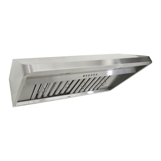
- Page 1 KOBE Range Hoods Premium Series CH91 SQB-1 Series Model No. Under Cabinet: CH9130SQB-1 (30”) CH9136SQB-1 (36”) CH9142SQB-1 (42”) CH9148SQB-1 (48”) Wall Mount: CH9130SQB-WM-1 (30”) CH9136SQB-WM-1 (36”) CH9142SQB-WM-1 (42”) CH9148SQB-WM-1 (48”) INSTALLATION INSTRUCTIONS AND OPERATION MANUAL...
- Page 2 IMPORTANT READ THIS FIRST READ BEFORE INSTALLATION 1. Carefully check all contents of packages. 2. Thoroughly inspect the unit for any shipping damages, cosmetic damages or defects. 3. Have a certified contractor/electrician test the unit before installation. IF THERE IS ANY PROBLEM: 1.
-
Page 3: Table Of Contents
[ENGLISH] - READ AND SAVE THESE INSTRUCTIONS - CONTENTS IMPORTANT SAFETY INSTRUCTIONS ..................1 COMPONENTS OF PACKAGE....................3 INSTALLATION .......................... 4 OPERATING INSTRUCTIONS....................13 MAINTENANCE ........................15 SPECIFICATIONS ........................16 MEASUREMENTS & DIAGRAMS .....................17 PARTS LIST ..........................19 CIRCUIT DIAGRAM ........................23 TROUBLE SHOOTING ......................25 WARRANTY ..........................26 WARRANTY INFORMATION FORM ..................28 - READ ALL INSTRUCTIONS CAREFULLY BEFORE STARTING -... -
Page 4: Important Safety Instructions
KOBE RANGE HOODS authorized agents will automatically void the warranty. KOBE RANGE HOODS will not be held responsible for any damages to personal property or real estate or any bodily injuries whether caused directly or indirectly by the range hood. - Page 5 What to Do In The Event Of a Range Top Grease Fire • SMOTHER FLAMES with a tight fitting lid, cookie sheet, or metal tray, and then turn off the burner. KEEP FLAMMABLE OR COMBUSTIBLE MATERIAL AWAY FROM FLAMES. If the flames do not go out immediately, EVACUATE THE AREA AND CALL THE FIRE DEPARTMENT or 911.
-
Page 6: Components Of Package
M4 x 3/4" (4 for 30” &36”) M4 x 1-1/4” (8 for 42” & 48”) (4 for 30” & 36”) (8 for 42” & 48”) FOR MORE INFORMATION, PLEASE VISIT OUR W EBSITE www.koberangehoods.com CONTACT KOBE RANGE HOODS AT (626) 775-8880. -
Page 7: Installation
INSTALLATION PLEASE READ ENTIRE INSTRUCTIONS BEFORE PROCEEDING Calculation before Installation To calculate installation, please refer to TABLE 1 and TABLE 2. (All calculation in inches.) - FOR UNDER THE CABINET - TABLE 1 A = Height of Floor to Ceiling B = Height of Floor to Counter Top (Standard: 36") C = Preferred Height of Counter Top to... - Page 8 SAFETY WARNING HOOD MAY HAVE VERY SHARP EDGES; PLEASE WEAR PROTECTIVE GLOVES IF REMOVING ANY PARTS FOR INSTALLING, CLEANING OR SERVICING. NOTE: BE CAREFUL WHEN USING ELECTRICAL SCREWDRIVER, DAMAGE TO THE HOOD MAY OCCUR. Installation Contents UNDER THE CABINET WALL MOUNT...
- Page 9 UNDER CABINET INSTALLATION Figure 1 Preparation before Installation NOTE: TO AVOID DAMAGE TO YOUR HOOD, PREVENT DEBRIS FROM ENTERING THE VENT OPENING. Decide the location of the venting pipe from the hood to the outside. Refer to Figure 1. A straight, short vent run will allow the hood to perform more efficiently.
- Page 10 Align and secure Top Vent Cover {E} and 3-1/4” x Figure 5 10” Vent Cover (removed from rear exhaust) using 14 screws (13 screws taken from 6” exhaust. (Figure 5) Attach the 3-1/4” x 10” Exhaust {D} to rear exhaust (located inside hood) using 10 screws taken from rear vent cover.
- Page 11 Figure 7 Ductwork Installation 10. Use steel pipe to connect the exhaust on the hood to the ductwork. Use duct tape to make all joints secure and air tight. Install Accessories 11. Install the Oil Tunnel {G} into recess support near rear of hood.
- Page 12 WALL MOUNT INSTALLATION ***This installation required to have Duct Cover Model No. CH1120DC-1. Preparation before Installation Figure 9 NOTE: TO AVOID DAMAGE TO YOUR HOOD, PREVENT DEBRIS FROM ENTERING THE VENT OPENING. Decide the location of the venting pipe from the hood to the outside.
- Page 13 4. For Rear 3-1/4” x 10” vent installation only: Figure 13 Remove attached 6” exhaust and discard. (Figure 11) Keep 13 screws to install vent covers. Remove duct knockout from back of the hood and discard. (Figure 13) Unscrew 3-1/4” x 10” Vent Cover from rear exhaust (located inside hood);...
- Page 14 Figure 17 Wiring to Power Supply CAUTION If moving the cooking range is necessary to install the hood, turn off the power in an electric range at the main electrical box. SHUT OFF THE GAS BEFORE MOVING A GAS RANGE. RISK OF ELECTRICAL SHOCK.
- Page 15 Figure 19 Install Accessories 15. Install the Oil Tunnel {G} into recess support near rear of hood. Refer to Figure 19. 16. Install Baffle Filters {H} and Stainless Steel Spacers {I}. Angle baffle filter toward back of hood. Push the baffle filter up until almost level.
-
Page 16: Operating Instructions
Note: For best results, turn fan on prior to any preparation or cooking and keep fans running while cooking. Adjust speed as needed. Power Control Press Power Control to turn On/Off the range hood. Speed Control The fan will start on Speed #3. Press button to decrease the speed level.Press button to increase the speed level. - Page 17 shutoff or turn off fan without disabling ECO Mode. When fan is off and ECO Mode has been activated, the icon will appear in the LED Display. The icon will flash while ECO Mode is operating on QuietMode™. To deactivate, press and hold button until icon no longer appears in the LED Display.
-
Page 18: Maintenance
MAINTENANCE For optimal performance, clean the range hood surface and baffles regularly. To Clean Hood Surface CAUTION: NEVER USE ABRASIVE CLEANERS, PADS, OR CLOTHS. *** Regular care will help preserve its fine appearance. 1. Use only mild soap or detergent solutions. Dry surfaces using soft cloth. 2. -
Page 19: Specifications
SPECIFICATIONS MODEL / SIZE For Under Cabinet Application For Wall Mount Application CH9130SQB-1 (30”) CH9130SQB-WM-1 (30”) CH9136SQB-1 (36”) CH9136SQB-WM-1 (36”) CH9142SQB-1 (42”) CH9142SQB-WM-1 (42”) CH9148SQB-1 (48”) CH9148SQB-WM-1 (48”) COLOR 18-Gauge Commercial Grade Stainless Steel CONSUMPTION / AMPERE 232W / 2.21A (30”, 36”) 235W / 2.23A (42”, 48”) NUMBER OF BLOWER DESIGN... -
Page 20: Measurements & Diagrams
MEASUREMENTS & DIAGRAMS ***All inch measurements are converted from millimeters. Inch measurements are estimated. ***All measurements in ( ) are millimeters. -FOR UNDER THE CABINET- MODEL NO.: CH9130SQB-1 (30”) CH9136SQB-1 (36”) CH9142SQB-1 (42”) CH9148SQB-1 (48”) 30" = Knockout Holes "A" 36”, 42”... - Page 21 ***Hood-Mounting Bracket ***Duct Cover-Mounting Bracket ***Duct Cover Support...
-
Page 22: Parts List
PARTS LIST MODEL NO.: CH9130SQB-1 and CH9130SQB-WM-1 (30”) CH9136SQB-1 and CH9136SQB-WM-1 (36”) DESCRIPTION MODEL /SIZE PART NO. 6” Exhaust Plate L1-0241-0001A Vent Cover (Top) L1-0241-0001B L1-0241-0002BH 2-3/4” x 9-3/4” Exhaust Plate 3-3/4” x 11-1/4” Vent Cover L1-0241-0002A 6” Round Plastic Exhaust L1-0505-0003 L1-0403-0301 LED Lights (3W) - Page 23 MODEL NO.: CH9130SQB-1 and CH9130SQB-WM-1 (30”) CH9136SQB-1 and CH9136SQB-WM-1 (36”)
- Page 24 MODEL NO.: CH9142SQB-1 and CH9142SQB-WM-1 (42”) CH9148SQB-1 and CH9148SQB-WM-1 (48”) DESCRIPTION MODEL /SIZE PART NO. 6” Exhaust Plate L1-0241-0001A Vent Cover (Top) L1-0241-0001B 2-3/4” x 9-3/4” Exhaust Plate L1-0241-0002BH 3-3/4” x 11-3/4” Vent Cover L1-0241-0002A 6” Round Plastic Exhaust L1-0505-0003 LED Light (3W) L1-0403-0301 B101-19142-06...
- Page 25 MODEL NO.: CH9142SQB-1 and CH9142SQB-WM-1 (42”) CH9148SQB-1 and CH9148SQB-WM-1 (48”)
-
Page 26: Circuit Diagram
CIRCUIT DIAGRAM MODEL NO.: CH9130SQB-1 and CH9130SQB-WM-1 (30”) CH9136SQB-1 and CH9136SQB-WM-1 (36”) - Page 27 MODEL NO.: CH9142SQB-1 and CH9142SQB-WM-1 (42”) CH9148SQB-1 and CH9148SQB-WM-1 (48”)
-
Page 28: Trouble Shooting
TROUBLE SHOOTING Issue Possible Cause Solution After The power is not on. Make sure the circuit breaker and the unit’s Installation, power is ON. Use a voltage meter to check both motors the power supply. and lights are The wire connection is not secure. Check and tighten wire connection. not working. -
Page 29: Warranty
TWO-YEAR LIMITED LABOR WARRANTY ON KOBE PREMIUM SERIES: For two years from the date of your original invoice from a KOBE authorized dealer, we will repair any parts or components free of charge that failed due to manufacturing defects. KOBE reserves the right to replace, rather than repair the product free of charge at our sole discretion. - Page 30 TO REQUEST WARRANTY SERVICE, PLEASE CONTACT KOBE RANGE HOODS SERVICE CENTER: From the 48 contiguous states: Email (best): customer.service@koberangehoods.com...
-
Page 31: Warranty Information Form
For warranty service or spare parts purchase in US, contact: KOBE Service Center Email (best): customer.service@koberangehoods.com Phone: 1-626-775-8880 ext. 103 Toll Free: 1-877-BUY-KOBE (289-5623) For warranty service or spare parts purchase in Canada, contact: Email (best): customer.service@koberangehoods.com Phone: 1-626-775-8880 ext. 103... - Page 32 Arcadia, CA 91006 USA www.koberangehoods.com This KOBE hood is made for use in the USA and CANADA only. We do not recommend using this hood overseas as the power supply may not be compatible and may violate the electrical code of that country. Using a KOBE hood overseas is at your own risk and will void your warranty.
Need help?
Do you have a question about the CH91 SQB-1 Series and is the answer not in the manual?
Questions and answers