Table of Contents
Advertisement
Quick Links
Handbook Contents
Safety
Technical Specification
This symbol is used to alert the user to important
operating or maintenance instructions.
The Lightning bolt triangle is used to alert the user
to the risk of electric shock.
SAFETY
1. It is important to read these instructions, and to follow them.
2. Keep this instruction manual in an accessible place.
3. Do not install this equipment near any heat sources such as radiators, heating
vents or other apparatus that produces heat.
4.
WARNING THIS APPARATUS MUST BE EARTHED.
(AC Version only )
5.
The ILD14 is designed to be permanently connected apparatus and must
be installed with all applicable installation regulations. A readily accessible
disconnect device shall be incorporated in the building installation power
wiring.
6. Mount the ILD14 with the wiring entering from the bottom of the unit if possible.
Failure of, or incorrect seating of any of the cable glands, may allow liquid or
moisture to enter the unit.
7. Refer all servicing and installation to qualified personnel.
8. The amplifier generates some heat during normal operation and needs
adequate ventilation. It should not be fitted in a fully enclosed space.
9.
Ensure the mains power cable is properly secured and insulated by using
the spiral wrap supplied. Ensure earth is connected to chassis
(AC Version only) see installation.
10. Fit the correct sealing insert in each gland according to the type of wire used, 2
wire, 4 wire or round section. Where all three inputs are used and the Status
output, you will need to use a multicore type cable consisting of multiple twisted
pairs having a round outer profile.
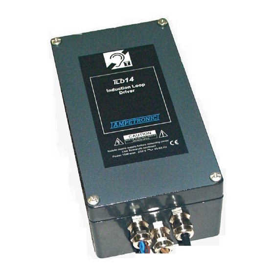
ILD14 HANDBOOK
Box Contents
1 x ILD14 Amplifier
1 x Earth crimp terminal
1 x Spiral mains cable wrap
1 x 2 hole sealing insert
1 x 4 hole sealing insert
1 x T200mAL fuse for 115V ONLY
Advertisement
Table of Contents

Related Manuals for Ampetronic ILD14


Summary of Contents for Ampetronic ILD14
- Page 1 6. Mount the ILD14 with the wiring entering from the bottom of the unit if possible. Failure of, or incorrect seating of any of the cable glands, may allow liquid or moisture to enter the unit.
- Page 2 It is intended to be used in harsh environments, being waterproof and fire safe. The ILD14 has three inputs that allow connection to a 100V line system and two line inputs. One line input can be specified as a microphone input at no extra cost by special order.
- Page 3 QUICK START For those who have a good appreciation of loop systems, the following is a very quick guide to setting up the amplifier: Turn all controls fully anti-clockwise. Connect loop cable. Connect signal input(s). Connect power. See point 9 in Safety Section. Switch on - Check green LED illuminates to show power OK.
-
Page 4: Block Diagram
Power LED 12V DC Version Power Fuse Power Supply input Power LED Inputs 100V speaker line Input 1 I/P1 Outputs Status ILD14 contact closed Low Z Speaker feed when amplifier functional Input 2 I/P2 ILD14 Twist together Loop output Loop... - Page 5 The four-wire sealing insert is 4 x 3.5mm maximum cable diameter. Operation The ILD14 is normally supplied as a 115V / 230V AC input. A 12V DC input version is available. Make sure you have the right voltage supply and selection before switching on the supply 1.
- Page 6 8. Repeat item 6 for each input used. When adjusting each input, make sure that the signal(s) are removed from the other inputs. This ensures that all signals are set to equivalent loudness and drive the compressor properly. 9. Monitor the output using an induction loop tester or headphone receiver (such as the ILR3) for adequate volume.
-
Page 7: Technical Specifications
Accessories Loop Ratio Adapter (LRA11). Weight 1.32 kg. Allows connection to specialised high current loops e.g. as used in help points. N.B Contact Ampetronic technical dept.in order to discuss your requirements. TECHNICAL SPECIFICATIONS Power Supply (AC): Loop Design: Nominal Supply Voltage:230V 45-65Hz Depends on application. - Page 8 This product carries a five year parts and labour warranty which could be invalidated if these instructions are not followed correctly, or if the unit is misused in any way. The five year warranty is dated from the time the equipment leaves Ampetronic and NOT when it is installed. DECLARATION OF CONFORMITY Manufacturer: Ampetronic Ltd.,...
Need help?
Do you have a question about the ILD14 and is the answer not in the manual?
Questions and answers