Table of Contents
Advertisement
Available languages
Available languages
Quick Links
Advertisement
Table of Contents

Subscribe to Our Youtube Channel
Related Manuals for Aim-TTI EX1810R


Summary of Contents for Aim-TTI EX1810R
- Page 1 EX1810R Bench Power Supply INSTRUCTION MANUAL...
-
Page 2: Table Of Contents
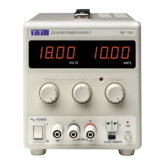
Introduction The EX1810R is an exceptionally compact and lightweight single output laboratory dc power supply providing 0 to 18V at 0 to 10A. The EX1810R uses mixed−mode regulation technology which combines switch−mode pre−regulation with linear post−regulation. Special techniques are used to maintain very high efficiency whilst achieving noise levels that are close to that of a pure linear regulator. -
Page 3: Specification
Specification OUTPUT Voltage Range: 0V to 18V minimum Current Range: 0A to 10A minimum Output Voltage Setting: By coarse and fine controls. Output Current Setting: By single logarithmic control. Operating Mode: Constant voltage or constant current with automatic cross-over. Output Switch: Electronic. -
Page 4: Safety
Safety This power supply is a Safety Class I instrument according to IEC classification and has been designed to meet the requirements of EN61010-1 (Safety Requirements for Electrical Equipment for Measurement, Control and Laboratory Use). It is an Installation Category II instrument intended for operation from a normal single phase supply. -
Page 5: Installation
Installation Mains Operating Voltage Check that the instrument operating voltage marked on the rear panel is suitable for the local supply. Mains Lead Connect the instrument to the AC supply using the mains lead provided. Should a mains plug be required for a different mains outlet socket, a suitably rated and approved mains lead set should be used which is fitted with the required wall plug and an IEC60320 C13 connector for the instrument end. -
Page 6: Operation
Operation Setting Up the Output With the POWER switch on ( ) and the output off the output voltage and current limit can be accurately preset using the VOLTAGE and CURRENT controls; the left-hand meter shows the set voltage and the right-hand meter shows the set maximum current. When the output switch is switched on, the ON lamp lights;... -
Page 7: Maintenance
Series or Parallel Connection with Other Outputs The outputs of the power supply are fully floating and may be used in series with other power supply units to generate high DC voltages up to 300V DC. The maximum permissible voltage between any terminal and earth ground ( ) is 300VDC. -
Page 8: Instructions En Francais
Sécurité Cet instrument est de Classe de sécurité 1 suivant la classification IEC et il a été construit pour satisfaire aux impératifs EN61010-1 (impératifs de sécurité pour le matériel électrique en vue de mesure, commande et utilisation en laboratoire). Il s'agit d'un instrument d'installation Catégorie II devant être exploité... - Page 9 Installation Tension d’utilisation secteur Vérifier que la tension opérationnelle de l'instrument indiquée sur le panneau arrière est appropriée pour l'alimentation locale. Câble secteur Branchez cet instrument sur l’alimentation secteur en utilisant le câble d’alimentation fourni. Si la prise murale requiert l’utilisation d’un câble d’alimentation différent, un câble approprié et approuvé, qui possède une fiche correspondante à...
- Page 10 Fonctionnement Réglage de la sortie L’interrupteur POWER (alimentation) sur ( ) et la sortie éteinte, il est possible de régler avec précision la limite de tension et de courant de sortie au moyen des commandes VOLTAGE (Tension) et CURRENT (Courant); l’appareil de mesure gauche indique la tension réglée et l’appareil droit le courant maximum réglé.
- Page 11 Placer le commutateur LOCAL/REMOTE en position LOCAL lorsque la détection distante n’est pas utilisée. Connexion en série ou en parallèle avec d’autres sorties Les sorties de l’alimentation sont entièrement flottantes et elles peuvent être utilisées en série avec d’autres blocs d’alimentation, afin de produire des tensions c.c. jusqu’à 300 V c.c. La tension maximale admissible entre une borne et la terre ( ) est de 300 V c.c.
- Page 12 AVERTISSEMENT! EMPECHER TOUTE INTRODUCTION D'EAU DANS LE BOITIER AFIN D'EVITER TOUT CHOC ELECTRIQUE ET DEGATS AU BLOC D'ALIMENTATION. NE JAMAIS UTILISER DE DISSOLVANTS POUR NETTOYER LE BLOC, AFIN D'EVITER D'ENDOMMAGER LE BOITIER OU LE CADRAN D’AFFICHAGE.
-
Page 13: Bedienungsanleitung Auf Deutsch
Sicherheit Dieses Gerät wurde nach der Sicherheitsklasse (Schutzart) I der IEC-Klassifikation und gemäß den europäischen Vorschriften EN61010-1 (Sicherheitsvorschriften für elektrische Meß-, Steuer, Regel- und Laboranlagen) entwickelt. Es handelt sich um ein Gerät der Installationskategorie II, das für den Betrieb von einer normalen einphasigen Versorgung vorgesehen ist. Das Gerät wurde gemäß... - Page 14 Installation Netzbetriebsspannung Sicherstellen, daß die auf der Geräterückwand angegebene Betriebsspannung mit der Versorgungsspannung am Ort übereinstimmt. Netzkabel Schließen Sie das Instrument unter Verwendung des mitgelieferten Netzkabels an die Wechselstromversorgung an. Falls ein Netzstecker für eine unterschiedliche Steckdose erforderlich ist, muss ein geeigneter zugelassener Netzkabelsatz verwendet werden, der mit der erforderlichen Steckdose und einem IEC60320 C13-Stecker für das Instrument versehen ist.
- Page 15 Betrieb Einstellung des Ausgangs Bei eingeschaltetem POWER-Schalter (Netz I) und ausgeschaltetem Ausgang läßt sich die Ausgangsspannung und Strombegrenzung mit Hilfe der Knöpfe VOLTAGE (Spannung) und CURRENT (Strom) genau voreinstellen. Die linke Anzeige zeigt die eingestellte Spannung und die rechte den eingestellten Maximalstrom an. Wenn der Ausgangsschalter eingeschaltet wird, leuchtet die ON (Ein)-Leuchte auf.
- Page 16 Abtastleitung gegeben ist. Dies lässt sich auf zweierlei Arten erreichen: entweder indem die Leitungen miteinander verdrillt werden oder indem ein koaxial geschirmtes Kabel (Abtastung über den Innerleiter) verwendet wird. Auch ein Elektrolytkondensator direkt am Lastanschlusspunkt kann hier von Nutzen sein. Der Spannungsabfall darf bei keiner Ausgangsleitung mehr als 0.5 Volt betragen.
- Page 17 Wartung Die Hersteller bzw. deren Vertretungen im Ausland bieten die Reparatur von Geräten an, bei denen eine Störung aufgetreten ist. Wenn der Eigentümer die Wartungsarbeiten selbst durchführen möchte, hat er dafür Sorge zu tragen, daß diese Arbeiten ausschließlich von entsprechend qualifiziertem Personal und gemäß Wartungshandbuch ausgeführt werden, das direkt von den Herstellern oder deren Vertretungen im Ausland bezogen werden kann.
-
Page 18: Istruzioni In Italiano
Sicurezza Questo strumento appartiene alla Categoria di Sicurezza 1, secondo la classifica IEC, ed è stato progettato in modo da soddisfare i criteri EN61010-1 (requisiti di Sicurezza per Apparecchiature di misura, controllo e per uso in laboratorio). È uno strumento di Categoria d’installazione II ed è inteso per il funzionamento con un’alimentazione normale monofase. - Page 19 Installazione Tensione d’esercizio Controllare che la tensione d’esercizio dello strumento segnata sul pannello posteriore sia uguale a quella della rete elettrica locale. Cavo d’alimentazione Collegare lo strumento all’alimentazione di rete in corrente alternata utilizzando il cavo fornito. Se dovesse essere necessaria una spina di alimentazione diversa, utilizzare un set completo della spina necessaria e di un connettore tipo IEC60320 C13 adeguatamente dimensionati e omologati.
- Page 20 possibile generare. L’indicatore CC si accende per mostrare il funzionamento a corrente costante. Uscita di corrente istantanea Il comando di limitazione di corrente può essere impostato per limitare la corrente di uscita continua a livelli fino a 10mA. Tuttavia, in comune con tutti gli alimentatori da banco di precisione, sull’uscita è...
- Page 21 vari gruppi possono essere collegati in parallelo per erogare una corrente uguale alla somma dei limiti di corrente impostati. È da notare che i morsetti d’uscita hanno una portata nominale massima di 15A; se si fanno funzionare diverse uscite in parallelo per erogare correnti più alte di questo limite, il collegamento deve essere fatto a un terminale separato e non su uno dei morsetti.
-
Page 22: Instrucciones En Español
Seguridad Este es un instrumento de Clase de Seguridad I según la clasificación del IEC y ha sido diseñado para cumplir con los requisitos del EN61010-1 (Requisitos de Seguridad para Equipos Eléctricos para la Medición, Control y Uso en Laboratorio). Es un instrumento de Categoría de Instalación II propuesto para ser usado con un suministro monofásico normal. - Page 23 Instalación Tensión de la Red Eléctrica Verificar que la tensión de funcionamiento del instrumento que figura en el panel trasero concuerde con el suministro local. Cable de Red Conectar el instrumento al suministro de CA usando el cable de la red incluido. Si requiere un enchufe de la red para una toma de energía diferente, deberá...
- Page 24 Operación Ajuste de la Salida Con el interruptor POWER conectado ( ) y se pueden preajustar la salida de la tensión de salida y el límite de corriente con precisión usando los controles de VOLTAGE y CURRENT; el medidor a la izquierda indica la tensión ajustada y el medidor a la derecha indica la corriente máxima preajustada.
- Page 25 La caída de corriente en cada cable de salida no debe superar 0,5 V. Conmute el interruptor LOCAL/REMOTE de nuevo a LOCAL cuando no esté utilizando la detección remota. Conexión en Serie o en Paralelo a Otras Salidas Las salidas del suministro de fuerza son completamente flotantes y pueden emplearse en serie con otras unidades de suministro de fuerza para generar altos voltajes de CC de hasta 300V CC.
- Page 26 Mantenimiento Los fabricantes o sus agentes en el extranjero ofrecen un servicio de reparación para toda unidad que desarrolle un defecto. Si los propietarios desearan establecer su propio servicio, esto sólo debe realizarse por personas cualificadas en conjunto con el manual de servicio que puede adquirirse directamente del Fabricante o de sus agentes en el extranjero.
- Page 27 Thurlby Thandar Instruments Ltd. Glebe Road • Huntingdon • Cambridgeshire • PE29 7DR • England (United Kingdom) Telephone: +44 (0)1480 412451 • Fax: +44 (0)1480 450409 International web site: www.aimtti.com • UK web site: www.aimtti.co.uk Email: info@aimtti.com Aim Instruments and Thurlby Thandar Instruments...
Need help?
Do you have a question about the EX1810R and is the answer not in the manual?
Questions and answers