Table of Contents
Advertisement
Quick Links
Advertisement
Table of Contents

Related Manuals for Crestron DM Lite 4K60


Summary of Contents for Crestron DM Lite 4K60
- Page 1 DM Lite® 4K60 4:4:4 Extenders Product Manual Crestron Electronics, Inc.
- Page 2 Crestron disclaims any proprietary interest in the marks and names of others. Crestron is not responsible for errors in typography or photography.
-
Page 3: Table Of Contents
Connecting a Surface-Mountable Device Wall Plate Device Installation In the Box Installing a Wall Plate Device Connecting a Wall Plate Device Resources Crestron Support and Training Programmer and Developer Resources Product Certificates Product Manual — Doc. 9259A Contents • i... - Page 4 ii • Contents Product Manual — Doc. 9259A...
-
Page 5: Overview
4K60 with 4:4:4 color sampling. A CAT5e or higher cable is used to connect a DM Lite 4K60 4:4:4 transmitter to a DM Lite 4K60 4:4:4 receiver. For 1080p, WUXGA, and 2K signals, a cable length of up to 230 ft (70 m) is supported. -
Page 6: Models
Models The following table provides a list of DM Lite 4K60 4:4:4 transmitters and receivers. Model Description TRANSMITTERS Transmitters, Surface-Mountable HD-TX-4KZ-101 HDMI® Signal Extension over CATx Cable HD-TXA-4KZ-101 HDMI and Analog Audio Signal Extension over CATx Cable HD-TXC-4KZ-101 HDMI, RS-232, and IR Signal Extension over CATx Cable... - Page 7 Model Description HD-RXCA-4KZ-101 HDMI, RS-232, IR, and Analog Audio Signal Extension over CATx Cable Receivers, Wall Plate HD-RX-4KZ-101-1G-B HDMI Signal Extension over CATx Cable, 1 Gang, Black HD-RXC-4KZ-101-1G-B HDMI, RS-232, and IR Signal Extension over CATx Cable, 1 Gang, Black Product Manual —...
-
Page 8: Features
DM Lite Interoperability The DM Lite output port of a DM Lite 4K60 4:4:4 transmitter must be connected to a DM Lite input port of a DM Lite receiver or DMPS Lite switcher. Similarly, the DM Lite input port of a DM Lite 4K60 4:4:4 receiver must be connected to a DM Lite output port of a DM Lite transmitter or DMPS Lite switcher. -
Page 9: 4K60 4:4:4 And Hdr Support
(for example, the HD-TX-101-C-E transmitter and the HD-RX-101-C-E receiver). A DM Lite 4K60 4:4:4 transmitter and receiver can be configured and controlled only when the devices are paired with a DMPS Lite switcher. The web interface of the switcher can be used to configure the DM Lite devices. -
Page 10: Analog Audio De-Embedding (Certain Models Only)
An audio selection push button is provided to switch between analog and HDMI audio inputs as desired. The audio selection push button is functional only when the transmitter is used with a DM Lite 4K60 4:4:4 receiver or a DMPS Lite HD-PS Series switcher. Analog Audio De-Embedding... -
Page 11: Physical Description
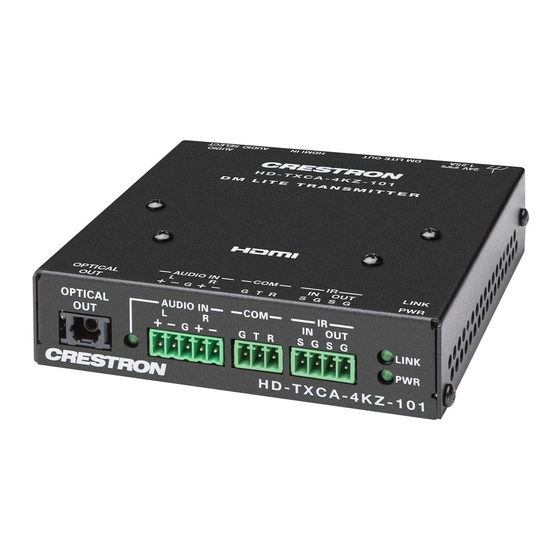
Physical Description The following sections provide information about the front and rear panels of DM Lite 4K60 4:4:4 extenders based on the device type (transmitter or receiver) and form factor (surface- mountable or wall plate): Surface-Mountable Transmitters Wall Plate Transmitters... - Page 12 Front Panel The following illustration shows the front panel of each of the HD-TX(A)(C)(CA)-4KZ-1x1 Series transmitters. HD-TX(A)(C)(CA)-4KZ-1x1 Series Transmitters, Front Panel OPTICAL OUT Port: JIS F05 female, TOSLINK® optical fiber connector; ① S/PDIF optical digital audio output, functional only when the HD-TXCA-4KZ-101 transmitter is used with the HD-RXCA-4KZ-101 receiver AUDIO IN LED: Green LED, indicates that analog audio is selected ②...
- Page 13 COM Port: 3-pin 3.5 mm detachable terminal block; ④ Bidirectional RS-232 port; Passes RS-232 TD/RD data to/from the COM port on a DM Lite receiver; Supports up to 115.2k baud IR IN/OUT Ports: 4-pin 3.5 mm detachable terminal block; ⑤ Comprised of (1) IR input port and (1) IR output port;...
- Page 14 Rear Panel The following illustration shows the rear panel of each of the HD-TX(A)(C)(CA)-4KZ-1x1 Series transmitters. HD-TX(A)(C)(CA)-4KZ-1x1 Series Transmitters, Rear Panel Ground: Chassis ground lug ① 24V 1.25A Power Connector: 2.1 x 5.5 mm DC power connector; ② 24VDC power input; PW-2420RU power pack included 10 •...
- Page 15 DM LITE OUT Port: 8-pin RJ-45 yellow connector, female, shielded; ③ DM Lite output port for connection to the DM Lite input port of a DM Lite receiver or DMPS Lite™ switcher; Green LED indicates that a DM Lite link is established; Flashing amber LED indicates non-HDCP video, and solid amber indicates HDCP video HDMI IN Port: HDMI Type A connector, female;...
- Page 16 HD-TX-4KZ-201 and HD-TX-4KZ-401 The front and rear panels of the HD-TX-4KZ-201 and HD-TX-4KZ-401 transmitters provide connectors, controls, and indicators as discussed in the following sections. Front Panel The following illustration shows the front panel of the HD-TX-4KZ-201 and HD-TX-4KZ-401 transmitters. HD-TX-4KZ-201 and HD-TX-4KZ-401 Transmitters, Front Panel PWR LED: Lights to indicate that power is being applied to the device.
- Page 17 Rear Panel The following illustration shows the rear panel of the HD-TX-4KZ-201 and HD-TX-4KZ-401 transmitters. HD-TX-4KZ-201 and HD-TX-4KZ-401 Transmitters, Rear Panel 24V 2.5A Power Connector: 2.1 x 5.5 mm DC power connector; ① 24VDC power input; PW-2420RU power pack included DM LITE OUT Port: 8-pin RJ-45 yellow connector, female, shielded;...
- Page 18 HD-TX-4KZ-211-CHGR and HD-TX-4KZ-421-CHGR The front and rear panels of the HD-TX-4KZ-211-CHGR and HD-TX-4KZ-421-CHGR provide connectors, controls, and indicators as discussed in the following sections. Front Panel The following illustration shows the front panel of the HD-TX-4KZ-211-CHGR and HD-TX-4KZ- 421-CHGR transmitters. HD-TX-4KZ-211-CHGR and HD-TX-4KZ-421-CHGR Transmitters, Front Panel PWR LED: Lights to indicate that power is being applied to the device.
- Page 19 SERVICE: USB 2.0 Type-A connector, female; ⑥ Used for firmware loading, configuration management, or as a USB host port for one TT-100 series cable caddy (sold separately); Can also provide up to 5V 500 mA power to a USB powered device Rear Panel The following illustration shows the rear panel of the HD-TX-4KZ-211-CHGR and HD-TX-4KZ- 421-CHGR transmitters.
-
Page 20: Wall Plate Transmitters
NOTE: In order for a USB-C DisplayPort input to charge the connected AV source, the DM Lite transmitter must be powered by the included power pack. If the device is powered by a remote DM Lite receiver or DMPS Lite switcher, no charging capability is provided by the USB-C input. - Page 21 Front View The following illustration shows the front of the HD-TX(A)(C)-4KZ-1x1-1G Series transmitters. HD-TX(A)(C)-4KZ-1x1-1G Series Transmitters, Front LINK LED: Green LED, indicates that a DM Lite link is established ① PWR LED: Lights to indicate that power is being applied to the device. Amber indicates ②...
- Page 22 HDMI IN Port: HDMI Type A connector, female; ④ HDMI digital video/audio input; DVI and Dual-Mode DisplayPort™ interface compatible with appropriate adapter or interface cable (CBL-HD-DVI interface cables sold separately) AUDIO SELECT: Push button, enables selection of HDMI or analog audio ⑤...
- Page 23 Rear View The following illustration shows the rear of the HD-TX(A)(C)-4KZ-1x1-1G Series transmitters. HD-TX(A)(C)-4KZ-1x1-1G Series Transmitters, Rear Ground: Chassis ground lug ① DM LITE OUT Port: 8-pin RJ-45 yellow connector, female, shielded; ② DM Lite output port for connection to the DM Lite input port of a DM Lite receiver or DMPS Lite™...
- Page 24 HD-TX-4KZ-211-2G The front and rear of the HD-TX-4KZ-211-2G transmitter provide connectors, controls, and indicators as discussed in the following sections. Front View The following illustration shows the front of the HD-TX-4KZ-211-2G. HD-TX-4KZ-211-2G, Front HDMI IN Port: HDMI Type A connector, female; ①...
- Page 25 USB IN Port: USB Type-C® connector, female; ⑦ Digital video/audio input using DisplayPort Alt Mode (CBL-USB3G1-C-C-6 and CBL- USB3G2-C-C-3 cables sold separately) USB IN LED: Green LED, lights to indicate that the device is receiving a DisplayPort ⑧ over USB-C (DisplayPort Alt Mode) input signal RESET Push Button: Restores factory default settings ⑨...
-
Page 26: Surface-Mountable Receivers
Surface-Mountable Receivers This section provides information about the front and rear panels of the HD-RX(A)(C)(CA)-4KZ- 101 Series receivers, which consist of the following: HD-RX-4KZ-101 HD-RXA-4KZ-101 HD-RXC-4KZ-101 HD-RXCA-4KZ-101 Front Panel The following illustration shows the front panel of each of the HD-RX(A)(C)(CA)-4KZ-101 Series receivers. - Page 27 COM Port: 3-pin 3.5 mm detachable terminal block; ③ Bidirectional RS-232 port; Passes RS-232 TD/RD data to/from the COM port on a DM Lite transmitter; Supports up to 115.2k baud IR IN/OUT Ports: 4-pin 3.5 mm detachable terminal block; ④ Comprised of (1) IR input port and (1) IR output port;...
-
Page 28: Wall Plate Receivers
Wall Plate Receivers This section provides information about the front and rear of the HD-RX(C)-4KZ-101-1G Series wall plate receivers, which consist of the following: HD-RX-4KZ-101-1G-B HD-RXC-4KZ-101-G-B Front View The following illustration shows the front of the HD-RX(C)-4KZ-101-1G Series receivers. HD-RX(C)-4KZ-101-1G Series Receivers, Front LINK LED: Green LED, indicates that a DM Lite link is established ①... - Page 29 IR IN/OUT Ports: 4-pin 3.5 mm detachable terminal block; ⑥ Comprised of (1) IR input port and (1) IR output port; IR IN passes the IR input signal to the IR OUT port on the DM Lite transmitter; IR OUT transmits the IR signal from the IR IN port on the DM Lite transmitter; Supports IR up to 60 kHz Rear View The following illustration shows the rear of the HD-RX(C)-4KZ-101-1G Series receivers.
-
Page 30: Specifications
Specifications For product specifications, visit the product pages on the Crestron website. The product pages are listed below based on device type (transmitter or receiver) and form factor (surface- mountable or wall plate). Transmitters, Surface-Mountable: HD-TX-4KZ-101 HD-TXA-4KZ-101 HD-TXC-4KZ-101 HD-TXCA-4KZ-101 HD-TX-4KZ-111... -
Page 31: Installation
DM Lite Cabling The DM Lite output port of a DM Lite 4K60 4:4:4 transmitter must be connected to a DM Lite input port of a DM Lite receiver or DMPS Lite switcher. Similarly, the DM Lite input port of a DM Lite 4K60 4:4:4 receiver must be connected to a DM Lite output port of a DM Lite transmitter or DMPS Lite switcher. -
Page 32: Hdmi Cabling
An HDMI input requires an appropriate adapter or interface cable to accommodate a Dual- Mode DisplayPort™ or DVI signal. An HDMI output requires an appropriate adapter or interface cable to accommodate a DVI signal. Crestron CBL-HD-DVI interface cables are sold separately. 28 • DM Lite® 4K60 4:4:4 Extenders... -
Page 33: Power Connection
Power Connection Be aware of the following guidelines regarding the power connection for a surface-mountable transmitter, surface-mountable receiver, wall plate transmitter, and wall plate receiver. Surface-Mountable Transmitter Power Connection A 24VDC power pack is included with a surface-mountable DM Lite transmitter. Be aware of the following: When a surface-mountable DM Lite transmitter is paired with a surface-mountable DM Lite receiver, either the power pack included with the transmitter or the receiver can be... - Page 34 Wall Plate Transmitter Power Connection No power pack is included with a wall plate DM Lite transmitter. Be aware of the following: When a wall plate DM Lite transmitter is paired with a surface-mountable DM Lite receiver, the power pack included with the receiver is used to power both devices. Power is transmitted over the CATx cable that connects the wall plate transmitter to the surface- mountable receiver.
-
Page 35: Surface-Mountable Device Installation
Surface-Mountable Device Installation This section provides information about installing and making connections to surface-mountable DM Lite transmitters and receivers. In the Box Qty. Description DM Lite transmitter or receiver, surface mountable Additional Items HD-TX-4KZ-101, HD-TX-4KZ-111, and HD-RX-4KZ-101 Only Bracket, Mounting (2057072) Screw, 4-40 x 1/4 in. - Page 36 Qty. Description Power Cord, 5 ft 10 in. (1.78 m) (2042043) Connector, 3-Pin (2003575) Connector, 4-Pin (2003576) HD-TXCA-4KZ-101 and HD-RXCA-4KZ-101 Only Bracket, Mounting (2057072) Screw, 4-40 x 1/4 in. Pan Head, Phillips (2007158) Screw, 6-32 x 3/4 in. Pan Head, Phillips (2007247) Anchor, Wall, #6 x 1-5/16 in.
-
Page 37: Installing A Surface-Mountable Device
Installing a Surface-Mountable Device Using the included mounting hardware, mount the device onto a flat surface such as a wall. The device can also be mounted onto a rack rail. Attaching Mounting Brackets Using the four included 4-40 x 1/4 in. Phillips pan head screws, attach the two included brackets to the left and right side of the device. - Page 38 Bracket Attachment, HD-TX-4KZ-421-CHGR Shown Mounting onto a Wall To mount the device onto a wall, use the four included anchors and screws. Depending on the DM Lite model, either 6-32 x 3/4 in. Phillips pan head screws or 6-32 x 3/4 in. combo truss head screws are included.
- Page 39 Wall Mounting, HD-TXCA-4KZ-101 Shown Product Manual — Doc. 9259A DM Lite® 4K60 4:4:4 Extenders • 35...
- Page 40 Wall Mounting, HD-TX-4KZ-421-CHGR Shown Mounting onto a Rack Rail To mount a surface-mountable device onto a single rack rail: 1. Position one of the mounting brackets so that the holes align with the holes in the rack rail. 2. Secure the device to the rack rail using two rack mount screws (not included). For example purposes, mounting of the HD-TXCA-4KZ-101 onto a rack rail is shown in the following illustration.
- Page 41 Rack Rail Mounting, HD-TXCA-4KZ-101 Shown Product Manual — Doc. 9259A DM Lite® 4K60 4:4:4 Extenders • 37...
-
Page 42: Connecting A Surface-Mountable Device
Connecting a Surface-Mountable Device This section provides information about the following: Surface-mountable transmitter connections Surface-mountable receiver connections Surface-Mountable Transmitter Connections This section provides information about making connections to the following surface-mountable transmitters: HD-TX-4KZ-101 HD-TX-4KZ-201 HD-TXA-4KZ-101 HD-TX-4KZ-211-CHGR HD-TXC-4KZ-101 HD-TX-4KZ-401 HD-TXCA-4KZ-101 HD-TX-4KZ-421-CHGR HD-TX-4KZ-111 HD-TX-4KZ-101 Connections Refer to the following illustration for general information about HD-TX-4KZ-101 rear panel... - Page 43 HD-TXA-4KZ-101 Connections Refer to the following illustration for general information about HD-TXA-4KZ-101 front and rear panel connections. NOTE: For guidelines regarding DM Lite cabling, HDMI cabling, and the surface-mountable transmitter power connection, refer to Installation Guidelines. HD-TXA-4KZ-101 Front and Rear Panel Connections Product Manual —...
- Page 44 The front panel of the device includes a 5-pin terminal block connector for balanced or unbalanced analog audio input. Refer to the following table and diagram for pin assignments and connection information. Analog Audio Input Pin Assignments Signal Name Balanced Audio Input Unbalanced Audio Input L+ In L- Signal return, jumper to GND...
- Page 45 HD-TXC-4KZ-101 Connections Refer to the following illustration for general information about HD-TXC-4KZ-101 front and rear panel connections. NOTE: For guidelines regarding DM Lite cabling, HDMI cabling, and the surface-mountable transmitter power connection, refer to Installation Guidelines. HD-TXC-4KZ-101 Front and Rear Panel Connections Product Manual —...
- Page 46 HD-TXCA-4KZ-101 Connections Refer to the following illustration for general information about HD-TXCA-4KZ-101 front and rear panel connections. NOTE: For guidelines regarding DM Lite cabling, HDMI cabling, and the surface-mountable transmitter power connection, refer to Installation Guidelines. HD-TXCA-4KZ-101 Front and Rear Panel Connections 42 •...
- Page 47 The front panel of the device includes a 5-pin terminal block connector for balanced or unbalanced analog audio input. Refer to the following table and diagram for pin assignments and connection information. Analog Audio Input Pin Assignments Signal Name Balanced Audio Input Unbalanced Audio Input L+ In L- Signal return, jumper to GND...
- Page 48 HD-TX-4KZ-111 Connections Refer to the following illustration for general information about HD-TX-4KZ-111 rear panel connections. NOTE: For guidelines regarding DM Lite cabling and the surface-mountable transmitter power connection, refer to Installation Guidelines. HD-TX-4KZ-111 Rear Panel Connections 44 • DM Lite® 4K60 4:4:4 Extenders Product Manual —...
- Page 49 HD-TX-4KZ-201 Connections Refer to the following illustration for general information about HD-TX-4KZ-201 front and rear panel connections. NOTE: For guidelines regarding DM Lite cabling, HDMI cabling, and the surface-mountable transmitter power connection, refer to Installation Guidelines. HD-TX-4KZ-201 Front and Rear Panel Connections Product Manual —...
- Page 50 HD-TX-4KZ-211-CHGR Connections Refer to the following illustration for general information about HD-TX-4KZ-211-CHGR front and rear panel connections. NOTE: For guidelines regarding DM Lite cabling, HDMI cabling, and the surface-mountable transmitter power connection, refer to Installation Guidelines. HD-TX-4KZ-211-CHGR Front and Rear Panel Connections 46 •...
- Page 51 HD-TX-4KZ-401 Connections Refer to the following illustration for general information about HD-TX-4KZ-401 front and rear panel connections. NOTE: For guidelines regarding DM Lite cabling, HDMI cabling, and the surface-mountable transmitter power connection, refer to Installation Guidelines. HD-TX-4KZ-401 Front and Rear Panel Connections Product Manual —...
- Page 52 HD-TX-4KZ-421-CHGR Connections Refer to the following illustration for general information about HD-TX-4KZ-421-CHGR front and rear panel connections. NOTE: For guidelines regarding DM Lite cabling, HDMI cabling, and the surface-mountable transmitter power connection, refer to Installation Guidelines. HD-TX-4KZ-421-CHGR Front and Rear Panel Connections 48 •...
- Page 53 Surface-Mountable Receiver Connections This section provides information about making connections to the following surface-mountable receivers: HD-RX-4KZ-101 HD-RXA-4KZ-101 HD-RXC-4KZ-101 HD-RXCA-4KZ-101 HD-RX-4KZ-101 Connections Refer to the following illustration for general information about HD-RX-4KZ-101 rear panel connections. NOTE: For guidelines regarding DM Lite cabling, HDMI cabling, and the surface-mountable receiver power connection, refer to Installation Guidelines.
- Page 54 HD-RXA-4KZ-101 Connections Refer to the following illustration for general information about HD-RXA-4KZ-101 front and rear panel connections. NOTE: For guidelines regarding DM Lite cabling, HDMI cabling, and the surface-mountable receiver power connection, refer to Installation Guidelines. HD-RXA-4KZ-101 Front and Rear Panel Connections 50 •...
- Page 55 The front panel of the device includes a 5-pin terminal block connector for balanced or unbalanced analog audio output. Refer to the following table and diagrams for pin assignments and connection information. Analog Audio Output Pin Assignments Signal Name Balanced Audio Output Unbalanced Audio Output L+ Out Open...
- Page 56 HD-RXC-4KZ-101 Connections Refer to the following illustration for general information about HD-RXC-4KZ-101 front and rear panel connections. NOTE: For guidelines regarding DM Lite cabling, HDMI cabling, and the surface-mountable receiver power connection, refer to Installation Guidelines. HD-RXC-4KZ-101 Front and Rear Panel Connections 52 •...
- Page 57 HD-RXCA-4KZ-101 Connections Refer to the following illustration for general information about HD-RXCA-4KZ-101 front and rear panel connections. NOTE: For guidelines regarding DM Lite cabling, HDMI cabling, and the surface-mountable receiver power connection, refer to Installation Guidelines. HD-RXCA-4KZ-101 Front and Rear Panel Connections Product Manual —...
- Page 58 The front panel of the device includes a 5-pin terminal block connector for balanced or unbalanced analog audio output. Refer to the following table and diagrams for pin assignments and connection information. Analog Audio Output Pin Assignments Signal Name Balanced Audio Output Unbalanced Audio Output L+ Out Open...
-
Page 59: Wall Plate Device Installation
Wall Plate Device Installation This section provides information about installing and making connections to DM Lite wall plate transmitters and receivers. In the Box Qty. Description DM Lite transmitter or receiver, wall plate Additional Items HD-TX-4KZ-101-1G(-B, -W), HD-TX-4KZ-111-1G(-B, -W), and HD-RX-4KZ-101-1G-B Only Screw, 6-32 x 3/4 in. - Page 60 1. Verify that the required wiring has been fed through the electrical box, and then make connections to the rear of the device. NOTE: For guidelines regarding DM Lite cabling and the wall plate transmitter and receiver power connection, refer to Installation Guidelines.
- Page 61 3. Attach a decorator style faceplate (not included) to the front of the device using two screws (not included). NOTE: The optional Crestron FP-G1 Series faceplate assembly is sold separately.
- Page 62 Mounting of 1-Gang Device into Electrical Box, HD-TX-4KZ-101-1G Shown 58 • DM Lite® 4K60 4:4:4 Extenders Product Manual — Doc. 9259A...
- Page 63 Installing a 2-Gang Wall Plate Device To install a 2-gang wall plate device into an electrical box: 1. Verify that the required wiring has been fed through the electrical box, and then make connections to the rear of the device. NOTE: For guidelines regarding DM Lite cabling and the wall plate transmitter and receiver power connection, refer to Installation...
- Page 64 3. Attach an FP-G2-DM Series decorator style faceplate (black FP-G2-DM-B-T or white G2-DM-W-T, sold separately) to the front of the device. An FP-G2-DM Series faceplate is required. Faceplates other than the FP-G2- NOTE: DM Series are incompatible with DM Lite 2-gang wall plate devices. Mounting of 2-Gang Device into Electrical Box, HD-TX-4KZ-211-2G Shown Mounting onto a Rack Rail To mount a wall plate device onto a single rack rail:...
- Page 65 Rack Rail Mounting, HD-TX-4KZ-101-1G Shown Product Manual — Doc. 9259A DM Lite® 4K60 4:4:4 Extenders • 61...
-
Page 66: Connecting A Wall Plate Device
Connecting a Wall Plate Device This section provides information about the following: Wall plate transmitter connections Wall plate receiver connections Wall Plate Transmitter Connections This section provides information about making connections to the following wall plate transmitters: HD-TX-4KZ-101-1G HD-TXA-4KZ-101-1G HD-TXC-4KZ-101-1G HD-TX-4KZ-111-1G HD-TX-4KZ-211-2G HD-TX-4KZ-101-1G Connections... - Page 67 HD-TX-4KZ-101-1G Connections, Front and Rear Product Manual — Doc. 9259A DM Lite® 4K60 4:4:4 Extenders • 63...
- Page 68 HD-TXA-4KZ-101-1G Connections Refer to the following illustration for general information about connections to the front and rear of the HD-TXA-4KZ-101-1G. NOTE: For guidelines regarding DM Lite cabling, HDMI cabling, and the wall plate transmitter power connection, refer to Installation Guidelines. 64 •...
- Page 69 HD-TXA-4KZ-101-1G Connections, Front and Rear Product Manual — Doc. 9259A DM Lite® 4K60 4:4:4 Extenders • 65...
- Page 70 The front panel of the device includes a 5-pin terminal block connector for balanced or unbalanced analog audio input. Refer to the following table and diagram for pin assignments and connection information. Analog Audio Input Pin Assignments Signal Name Balanced Audio Input Unbalanced Audio Input L+ In L- Signal return, jumper to GND...
- Page 71 HD-TXC-4KZ-101-1G Connections, Front and Rear Product Manual — Doc. 9259A DM Lite® 4K60 4:4:4 Extenders • 67...
- Page 72 HD-TX-4KZ-111-1G Connections Refer to the following illustration for general information about connections to the front and rear of the HD-TX-4KZ-111-1G. NOTE: For guidelines regarding DM Lite cabling and the wall plate transmitter power connection, refer to Installation Guidelines. 68 • DM Lite® 4K60 4:4:4 Extenders Product Manual —...
- Page 73 HD-TX-4KZ-111-1G Connections, Front and Rear Product Manual — Doc. 9259A DM Lite® 4K60 4:4:4 Extenders • 69...
- Page 74 HD-TX-4KZ-211-2G Connections Refer to the following illustration for general information about connections to the front and rear of the HD-TX-4KZ-211-2G. NOTE: For guidelines regarding DM Lite cabling, HDMI cabling, and the wall plate transmitter power connection, refer to Installation Guidelines. 70 •...
- Page 75 HD-TX-4KZ-211-2G Connections, Front and Rear Product Manual — Doc. 9259A DM Lite® 4K60 4:4:4 Extenders • 71...
- Page 76 Wall Plate Receiver Connections This section provides information about making connections to the following wall plate receivers: HD-RX-4KZ-101-1G HD-RXC-4KZ-101-1G HD-RX-4KZ-101-1G Connections Refer to the following illustration for general information about connections to the front and rear of the HD-RX-4KZ-101-1G. NOTE: For guidelines regarding DM Lite cabling, HDMI cabling, and the wall plate receiver power connection, refer to Installation Guidelines.
- Page 77 HD-RX-4KZ-101-1G Connections, Front and Rear Product Manual — Doc. 9259A DM Lite® 4K60 4:4:4 Extenders • 73...
- Page 78 HD-RXC-4KZ-101-1G Connections Refer to the following illustration for general information about connections to the front and rear of the HD-RXC-4KZ-101-1G. NOTE: For guidelines regarding DM Lite cabling, HDMI cabling, and the wall plate receiver power connection, refer to Installation Guidelines. 74 •...
- Page 79 HD-RXC-4KZ-101-1G Connections, Front and Rear Product Manual — Doc. 9259A DM Lite® 4K60 4:4:4 Extenders • 75...
-
Page 80: Resources
Crestron Resource Library Crestron Online Help (OLH) Crestron Training Institute (CTI) Portal Programmer and Developer Resources help.crestron.com: Provides help files for Crestron programming tools such as SIMPL, SIMPL#, and Crestron Toolbox™ software developer.crestron.com: Provides developer documentation for Crestron APIs, SDKs, and other development tools Product Certificates To search for product certificates, refer to support.crestron.com/app/certificates. - Page 81 This page is intentionally left blank. Product Manual — Doc. 9259A DM Lite® 4K60 4:4:4 Extenders • 77...
- Page 82 Product Manual — Doc. 9259A Crestron Electronics, Inc. 15 Volvo Drive, Rockleigh, NJ 07647 07/25/22 Tel: 888.CRESTRON Specifications subject to Fax: 201.767.7656 change without notice. www.crestron.com...
Need help?
Do you have a question about the DM Lite 4K60 and is the answer not in the manual?
Questions and answers