Table of Contents

Related Manuals for Schmidt ZT Series


Summary of Contents for Schmidt ZT Series
- Page 1 S C H M I D T c o n t r o l i n s t r u m e n t s Edition ZT 02.E ZT Series Model ZTS Operating Instructions ZTS-DPU ZTA-DPU Valid as of: 01.01.2022 - Firmware 5.0 or later • Please keep the manual for future reference!
-
Page 2: Precautions
Precautions Cautions of overload Bend or twist Overload Incorrect direction • Keep in mind that this unit will break down if the force exceeding capacity is applied irrespective of power status. • If the force exceeding approx. 110% of capacity is applied, the following ZTA-500N ZTA-500N ZTA-500N... - Page 3 Cautions of storage • Please avoid oil, dust, and heat and high humidity, and keep it in a cool place. • Please keep it after use in an attached carrying case to prevent from force or a shock applying to a measuring shaft. •...
-
Page 4: Table Of Contents
Index Precautions ....... 1 - 2 Peak Value ........Features ........... 1st / 2nd Peak Value (ZTA, eZT only) ......Models ..........Output Names and Functions ....6 - 8 12-1. Output to USB memory Accessories ......9 - 10 (ZTA, eZT only) .... -
Page 5: Features
Features Thank you for choosing IMADA digital force gauge ZT series. This product has an easy-to-read display with superior specifications, and can be used for various kinds of tensile / compression measurement. Organic EL display, on-demand multi display and information in English lead easy operation. -
Page 6: Models
1. Models ZT series consists of ZTA series with USB memory connection and displacement output function, and ZTS series without the connection and function. The separated sensor models are also available. eZT series enable one amplifier to connect to various load cells of your choice. -
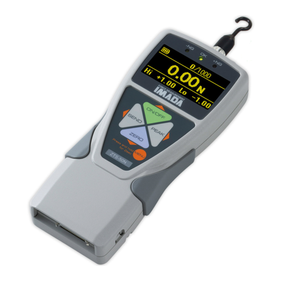
Page 7: Names And Functions
2. Names and Functions Names • Measuring shaft • Comparator judgment LED • Display • ON/OFF button • SEND button ZTA-500N • PEAK button • ZERO button • MENU button • I/O connector • Battery cover • USB connector • AC adaptor connector * Design and appearance differ depending on the model and range. - Page 8 2. Names and Functions 2. Names and Functions Display Display ① ② ③ ① ② ③ ① ② ⑥ ⑦ ③ ① ② ⑥ ⑦ ③ Single Display Single Display Multi Display Multi Display ⑧ ⑧ ⑨ ⑨ ⑩ ⑩ ④...
- Page 9 ① Battery / Battery status ② Displacement value zero / Valid or invalid: Zero displacement value at arbitrary force value. (Refer to page 26, [8. Function Setting, Displacement reset]) (*1) ③ Auto Zero Timer / Valid or invalid: Zero force value after arbitrary time. (Refer to page 26, [8.
-
Page 10: Accessories
3. Accessories The following accessories are included. Make sure to keep them in the carrying case. Carrying case is necessary when transport to protect the force gauge and its sensor. Accessories of ZTA / ZTS • Instruction manual (This book) •... - Page 11 For high capacity * Type B are included 2500 and 5000N capacity models. Flat Tip Conical Tip (B-2) (B-3) Small Hook Chisel Tip Notched Tip Extension Shaft 2 Exclusive 4 Installation (B-1) (B-4) (B-5) (B-6) Handles Bolts (B-7) (B-8) • Separated sensor model includes different attachments depending on load cell models.
-
Page 12: Preparation
4. Preparation 4-1. Battery and Charge Please charge before your first use of this product. Charging completes in approximately 2 hours when using the included AC adaptor. The battery icon shows the 3 remaining levels. It appears after the power is turned on. Please recharge when it shows It shows an animation of charging while connected with the AC adaptor. -
Page 13: Connecting To Ez Connect Load Cell (Ezt Only)
4-2. Connecting to eZ Connect load cell (eZT Only) eZT can be used with various eZ Connect load cells of your choice. Please connect a load cell with the power off. Turn it on to show connecting status on the amplifier as below. Disconnected Connected Once connected properly, the model of the eZ Connect load cell appears following the... -
Page 14: Mount Of Attachments
4. Preparation 4-3. Mount of Attachments Mount appropriate attachment to the measuring shaft. The direction can be adjusted with the included nut. • Applying the force to wrong direction or using tools to mount an attachment will cause load cell damage. For safety, please mount an attachment while checking a display value. -
Page 15: Mount To Test Stands
4-4. Mount on test stand This force gauge can be attached to a test stand. The four holes on the back can be used for mounting. Refer to the page 46. Standard mode Mount the force gauge to a mounting plate of a test stand with four screws included to the test stand. -
Page 16: Basic Operation
5. Basic Operation 5. Basic Operation The force gauge detects the force applied to the direction of a measuring shaft. The force gauge detects the force applied to the direction of a measuring shaft. The measurement is done on Peak mode or Track mode. The measurement is done on Peak mode or Track mode. -
Page 17: Single Display / Multi Display 6-1. Single Display
6. Single display / Multi display Select either Single display or Multi display. Refer to the page 27 for detail of toggling. 6-1. Single display Display force value only. * Displacement value can be checked on Multi display (ZTA, eZT only). Single display 6-2. - Page 18 6. Single display / Multi display 6. Single display / Multi display Refer to the page 20 for how to set. Refer to the page 20 for how to set. Multi Display: Menu on header. Multi Display: Menu on header. Contents Contents Description...
- Page 19 Multi Display: Menu on footer Contents Description Valid Model Set comparator High / Low values. Enable to set the values with (MENU button) while Comparator ZTA/ZTS this content lights on. Change values with High / Low values (ON/OFF, ZERO button) and enter with (MENU button).
-
Page 20: Initial Setting
7. Initial Setting 1. Turn off power. 2. Hold (MENU button) and turn on power with (ON/OFF button). 3. Select menu in Main menu with (ON/OFF, ZERO buttons), and go to Sub menu with (PEAK button). (Some menu doesn’t have Sub menu.) 4. - Page 21 Initial Setting (Setup Menu) Main menu Sub menu Setting menu Description Valid model Initial setting Change force units. [N] / [kN] / [mN] / [gf] / [kgf] / [ozf] / ZTA/ZTS N basis Force Units [lbf] (*1) (Valid selection Units differs depending on capacity.) [mm] / [°] /...
- Page 22 7. Initial Setting 7. Initial Setting Main menu Main menu Sub menu Sub menu Setting menu Setting menu Description Description Valid model Valid model Initial setting Initial setting Select zero contents. Select zero contents. [All reset]: Zero all the [All reset]: Zero all the displayed values.
- Page 23 Main menu Sub menu Setting menu Description Valid model Initial setting Choose signal setting of SEND input from outside. OFF: Read edge signal ZTA/ZTS Ext-Input Send [ON] / [OFF] when connected to GND. Invert Function ON: Read edge signal when departed GND. Select display type.
-
Page 24: Function Setting
8. Function Setting 1. Hold (MENU button) for more than two seconds while power is on. 2. Select menu in Main menu with (ON/OFF, ZERO button), and go to Sub menu with (PEAK button). (Some menu doesn’t have Sub menu.) 3. - Page 25 Function Setting (Program Menu) Main menu Sub menu Setting menu Description Valid model Initial setting Set Hi and Low values. LED and output signal show High +/- [0000 to 9999] whether the measurement +Capacity value is below, within, or above the set values. -NG: Displayed value <...
- Page 26 8. Function Setting 8. Function Setting Main menu Sub menu Setting menu Description Valid model Initial setting Main menu Sub menu Setting menu Description Valid model Initial setting [and] [and] Both compression and Both compression and tensile peak values are tensile peak values are displayed in order of displayed in order of...
- Page 27 Main menu Sub menu Setting menu Description Valid model Initial setting Zero the displacement value Displacement Absolute value 0000 Reset value when the force value Reset [0000 to 9999] (*1) reached to the set value. The saved data in the Data recall internal memory is displayed.
- Page 28 8. Function Setting 8. Function Setting Main menu Main menu Sub menu Sub menu Setting menu Setting menu Description Description Valid model Valid model Initial setting Initial setting [Single Display] [Single Display] Display force value only. Display force value only. [Multi Display] [Multi Display] [Single Display] /...
-
Page 29: Measurement Of Displacement (Zta, Ezt Only)
9. Measurement of Displacement (ZTA, eZT only) ZTA series and eZT can detect both force and displacement values. (A displacement meter needed.) Displacement Type is [OFF] at default. Select appropriate Displacement Type depending on displacement meters. 9-1. Connecting to IMADA Test Stand with Liner Scale Instruction manuals of test stands explain types of liner scales. - Page 30 9. Measurement of Displacement (ZTA, eZT only) It uses phaseA and phaseB together to know the direction. It reads incremental signals input in the 2 phases. An up/down edge is regarded as 1 count, in other words, please input a quarter of 1 signal period. For example In the case when you combine a ZTA with the displacement scale which uses line μ...
-
Page 31: Display Of Displacement
9-3. Display of displacement The displacement is displayed on the header on Multi display. Please refer to the page 17 for setting. 9-4. Display of displacement at peak force This function is recommended when graphing is not needed such as destruction test. When displacement is displayed on the header at Peak mode on Multi display, the displacement at peak force is displayed. -
Page 32: Peak Value
10. Peak Value Peak is the maximum force value of measurement. Press (PEAK button) and [P] or [Peak] is displayed at left side of display. [P] and [Peak] mean Peak mode. • In case of [OR] at Peak mode, higher peak value among compression and tensile peak values is displayed. -
Page 33: St / 2Nd Peak Value (Zta, Ezt Only)
11. 1st / 2nd Peak Value (ZTA, eZT only) The peaks of the first and the second curves, instead of the peak of whole measurement, can be detected. The 1st peak as [P1] and the 2nd peak as [P2] are displayed on the footer on Multi display. -
Page 34: Output
12. Output 12-1. Output to USB memory: ZTA series and eZT only ZTA and eZT can be connected to USB memory (excluded) using the included adapter. Data of internal memory can be sent to USB memory and measuring data of both real time and a single data can be saved in USB memory. - Page 35 12-1-2. Data transport Transport data in the internal memory to USB memory. Refer to page 26. [8.Function Setting, USB Memory] → → Program Menu USB Memory Export to USB The following message shows up during transport. (Do not remove the USB memory.) The message disappears when transport ends.
- Page 36 12. Output Start and stop of saving While (MEM mark) shows up, press (SEND button) to start saving data in USB memory. Press (SEND button) again to stop saving. (MEM mark) blinks during saving. * Please refer to the page 50-51 for file format of USB memory. * The data is saved in the new file of USB memory.
- Page 37 • Optional software Force Recorder is recommended for measurement with sudden force change such as destruction test. Force Recorder can receive 2000 data/sec the same speed of ZT series. • Do not disconnect USB memory during saving. • Please make sure to follow the direction to disconnect USB memory, otherwise data can be lost.
-
Page 38: Usb Output (Output To Pc)
12. Output 12-2. USB output (output to PC) ZTA / ZTS can be connected to PC with included USB cable. For compatible PCs, please check the operating environment of the software. 12-2-1. Connection to PC Connect the interface of force gauge and USB port of PC with the included USB cable. -
Page 39: Output On Rs232C/Usb
12-3. Output on RS232C/USB Connecting with external equipments, data transport and control of force gauges are possible. The connection is based on RS232C (optional cable) and USB (included cable). RS232C, Condition Data bits 8 bit Stop bit 1 bit Parity bit None Transmission rate 19200bps... -
Page 40: Analog Output
12. Output 12-4. Analog output 12-4-1. Analog output: D/A (standard spec.) Analog voltage is always output depending on measuring force value. (+/- 2V when max. force is applied.) Force value can be recorded at real time by connecting to external equipments with analog cable (excluded). -
Page 41: Wireless Transmission Adapter Facility
12-5. Wireless Transmission Adapter facility This instrument is compatible with a *Wireless Transmission Adapter (*sold separately) for the Wireless Transmission of the measurement values. Settings as follows: Setup Menu Wireless Setting Wireless Output When the Wireless Output ON, there are restrictions such as some functions that cannot be used at the same time. -
Page 42: Maintenance
13. Maintenance 13-1. Battery Change The force gauge has rechargeable battery inside. If the battery is worn out soon after charging or not charged at all, the battery is dying. Please change the batteries. (Battery model: BP-308) The direction is as follows. Turn off the force gauge. -
Page 43: Overall Accuracy Of Ezt And Ez Connect Load Cell (Ezt Only)
13-3. Overall Accuracy of eZT and eZ Connect load cell (eZT only) Overall accuracy is calculated as below (e.g. eZT and eDPU-50N): Overall Accuracy eZT Amplifier eDPU-50N Load cell +/- 0.4%F.S. 1digit +/- 0.2%F.S. 1digit +/- 0.2%F.S. 1digit eZT and eZ Connect load cells can be used in various combination, therefore each is tested individually. -
Page 44: Specifications
15. Specifications 15. Specifications Model Model Separate model connectable Separate model connectable Advanced model with various Advanced model with various Standard model with the Standard model with the to various sensors with ZTA to various sensors with ZTA functions such as data functions such as data same benefit in performance same benefit in performance... -
Page 45: Optional Items
16. Optional Items Test Stands For stable measurement, we recommend use force gauges with test stand. HV-500NⅡ MX2-500N MX2-1000N MX2-2500N Manual Test Stand Motorized Test Stand Motorized Test Stand Motorized Test Stand (High capacity) Optional Attachments Various kinds of attachments are available corresponding to very diverse shape of samples. FP-50 GR-30 KC-1001... - Page 46 16. Optional Items Graphing Software: Force-Recorder A smooth and accurate graph with USB connection. (2000 data / sec.) Professional Standard Light Main Functions ○ ○ ○ Force-Time graphing ○ ○ ○ Function setting of force gauge ○ ○ ○ Data storage in CSV format ○...
-
Page 47: Dimensions
17. Dimensions Standard High Capacity... -
Page 48: Output Data
18. Output Data 18-1. I / O connector Connector pin arrangement Pin number Signal name Description Valid model High Low setpoints of comparator output. ZTA/ZTS Either signal is output depending on comparator judgment. (*1)(*4) Output depending on set high / low output values. - Page 49 Pin number Signal name Description Valid model Optional EXSW1:POWER Input signal ZTA/ZTS/eZT The functions differ depending on signal of EXSW2:ZERO ZTA/ZTS/eZT Shift. Refer to the bottom of the page for EXSW3:SEND ZTA/ZTS/eZT detail. (Detect edge signal when each pin EXSW4:PEAK ZTA/ZTS/eZT connected to GND pin #30.) (*4)
-
Page 50: Connection Example Of I/O Terminals
18. Output Data 18. Output Data 18-2. Connection example of I/O terminals 18-2. Connection example of I/O terminals Connection example to output terminal of force gauge Connection example to output terminal of force gauge 1-7: 1-7: Output Output terminal terminal Output grand Output grand Max. -
Page 51: File Format Saved In Usb Memory (Zta Only)
18-3. File Format saved in USB memory (ZTA, eZT only) The file format saved in USB memory is as follows. The files are saved in “IMADA” directory of USB memory. File Format Description File name: R00001.csv File name: The continuous numbers follow after [R]. Contents: Each number is followed by comma and RRR[CR][LF]... -
Page 52: Command (Rs232C / Usb)
18. Output Data File Format Description File name: M00001.csv File name: The continuous numbers follow after [M]. Contents: Each number is followed by comma and yyyy,mm,dd,hh,nn,ss[CR][LF] saved in CSV style. YYYY,MM,DD,HH,NN,SS,ffffff,uuu, Contents: dddddddd,rrr[CR][LF] Data yyyy: Year / mm: Month / dd: Day YYYY,MM,DD,HH,NN,SS,ffffff,uuu, transport hh: hour (24 hours) / nn: minute / ss: second /... - Page 53 Category Command Setting Contents Receive Setting Format Example Description High / Low Output (*2) [f]: Setting value > Result, Value 1 ○ − XCO[f] XCO1 measuring value: 0 Setting value ≦ measuring value: 1 High / Low Output (*2) [s]: Setting value >...
- Page 54 18. Output Data Category Command Setting Contents Receive Setting Format Example Description Data save in internal memory (Data contents − ○ − depending on the setting of SEND button) Refer to “appended Output all the data [Memory Data 1] chart 1” (P57) for ○...
- Page 55 Category Command Setting Contents Receive Setting Format Example Description Continuous data Refer to “appended chart 1” (P57) for output (Force and format. displacement, ± ± fffff f+123.4+ ○ − 1/2000 sec.) dddddddPLCSX 123456701L00 *Error when sent to RS232C port Stop data output −...
- Page 56 18. Output Data Category Command Setting Contents Receive Setting Format Example Description Data output FFFFF: 4 digits force value with decimal (Interchangeable point with ZP/Z2 format) U: Unit number ○ − ± FFFFF UMC +123.4NTO M: Current mode C: Comparator judgment Save data −...
- Page 57 Category Command Setting Contents Receive Setting Format Example Description Change to Peak Operation depends on the setting of Mode PEAK button. [OR]: Display the measuring value => either higher value among +/- − ○ peak values. [AND]: Display the measuring value =>...
- Page 58 18. Output Data 18. Output Data Appended Chart 1. Format of force response Appended Chart 1. Format of force response ± ± ± ± fffff fffff dddddddPLCSX dddddddPLCSX [Measuring value / Peak value] [Measuring value / Peak value] ± ± ±...
- Page 59 Appended chart 3. Appended chart 2. Units list Unit setting numbers and units of displacement * Setting units are different depending on models. * Setting units are different depending on models. No unit inch (*) ° * Units selection differs between Japan model and on-Japan model.
- Page 60 Yarn Package Durometer and Shore-A Durometer Sample Cutter Balance Moisture Meter Leak Tester Softometer More than 70 years - Worldwide - Hans Schmidt & Co GmbH Phone: e-mail: Mailing address: int. + 49 / (0)8638 / 9410-0 info@hans-schmidt.com P. O. B. 1154...
Need help?
Do you have a question about the ZT Series and is the answer not in the manual?
Questions and answers