
Related Manuals for Schmidt ET Series


Summary of Contents for Schmidt ET Series
- Page 1 S C H M I D T c o n t r o l i n s t r u m e n t s Edition ETB 01.E ET Series Model Instruction Manual ETPB Valid as of: 01.11.2018 • Please keep the manual for future reference!
-
Page 2: Table Of Contents
Contents 1 Warranty and liability ....................4 1.1 Notices within the operating instructions ..............4 1.2 Responsibilities of the operating company ............. 4 1.3 Responsibilities of the personnel ................4 1.4 Informal safety measures ..................5 1.5 Training of the personnel ..................5 1.6 Intended use ...................... - Page 3 5 Cleaning........................27 6 Verification interval ....................27 7 Correspondence ..................... 27 8 Repairs........................27...
-
Page 4: Warranty And Liability
Warranty: - SCHMIDT tension meters are warranted for 12 months. Parts subject to wear, electronic components and measuring springs are not covered by the warranty. No warranty or liability will be accepted for bodily injury or property damage resul- ting from one or several of the following causes: - Misuse or abuse of the device. -
Page 5: Informal Safety Measures
The device is intended exclusively to be used as a tension meter. Any other use or any use exceeding this intention will be regarded as misuse. Under no circumstances shall HANS SCHMIDT & Co GmbH be held liable for damage resulting from misuse. The intended use also includes: - Complying with all notices included in the Operating Instructions and observing all inspection and maintenance works. -
Page 6: Available Models
Outer distance between outside guide rollers / pins ** Suitable for 95% of all applications. PA = Polyamide Monofilament. If the material to be measured differs significant from the SCHMIDT calibration material in diameter, rigidity, shape, etc., we recommend calibration using customer supplied material. -
Page 7: Connecting The Tension Meter
The requirements of the CE specification are only complied with if the tension meter is equipped and operated with equipment supplied by HANS SCHMIDT & Co GmbH. Certification to the CE specification does not extend to, and shall be invalid for any other combination. For damage resulting the- reby we assume no liability. -
Page 8: Id Plate, Ce Mark, Calibration Label
3.1.1 ID Plate, CE Mark, Calibration Label The ID plate with the CE mark and the serial number as well as the calibration label (optional) are provided on the backside of the instrument, the SCHMIDT Quality Seal is provided on the right side. -
Page 9: Mounting The Filament Guide
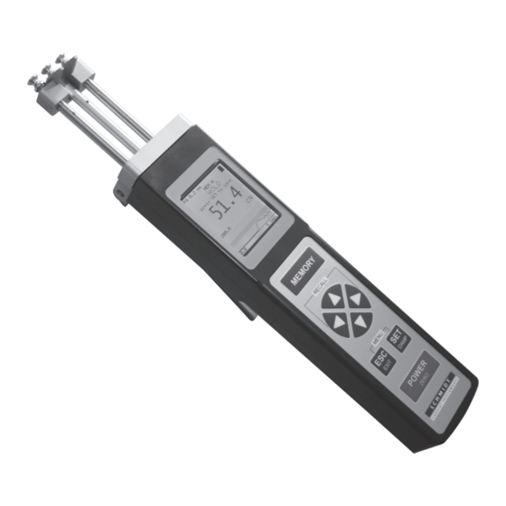
3.1.3 Mounting the Filament Guide Center Line fig. 3.1.3 Mounting: - Unscrew and remove the guide rollers (2x) with the supplied open end wrench (jaw width 4 mm). - Slip the filament guide on to the roller shafts. - Screw the guide rollers (2x) back on to the roller shafts and carefully tighten them with the supplied open end wrench (jaw width 4 mm) until hand-tight. - Page 10 3.2 Operating and display elements Numeric display Info on material Battery status indicator Data stored in the memory Cal. adjustment Damping Current reading Measurement unit MIN/MAX Alarm Display with bargraph Info on material Battery status indicator Data stored in the memory Cal.
-
Page 11: Setup
3.2 Operating and display elements Graphic display Battery status indicator Info on material Data stored in the memory Cal. adjustment Damping Tension range Measured values Measurement unit as graph Readings Measured values length of the between the as graph time axis alarm values The Y-axis can be scaled with the buttons. -
Page 12: Charging The Battery
Before you connect the AC adapter, verify that the supply voltage is correct (100 V - 240 V). HANS SCHMIDT & Co. GmbH provides no warranty or liability for any damage resulting from the use of AC adapters from other manufacturers. - Page 13 3.4 Tension meter settings Main Menu Submenu Settings Menu Description Material [1] to [4] Chapter 3.4.1 Material-Set-up Cal. — [- 10 %] - [+ 10 %] Chapter 3.5.6 Adjustment • Measured value displayed as number and alarm monitoring [numeric] • Measured value displayed as number, [Bargraph] Display bar graph trend display and alarm —...
-
Page 14: Material Menu
- Insert a password and choose a protection level - Exit the main menu, to apply the password protection The factory setted password is „0000“ If you forgot the password, please contact HANS SCHMIDT & Co GmbH to request the master password. -
Page 15: Factory Reset
3.4.3 Factory reset A factory reset resets the tension meter to its original manufacturer settings. This proce- dure will delete all settings, including any customer-defined material characteristics (calibrations); the factory calibration, however, will be kept. Customer calibrations will be deleted. Operation procedure Requirements: - Switch the tension meter on (chapter 3.3) -
Page 16: Inserting And Removing Material To Be Measured
3.5.2 Inserting and removing material to be measured Material to be Inserting the material to be measured: measured - Press the lever to tilt the outer guide Measuring Guide rollers rollers sidewards. roller - Thread the material to be measured through the measuring and guide rollers (filament guide). -
Page 17: Using The Alarm Function
3.5.4 Using the alarm function Requirements: In the Material Setup menu, make sure that the MIN and MAX limit values have been set for each material characteristic. The limit value alarm has to be enabled in the main menu. 3.5.5 Cal. Adjustment By performing a calibration adjustment, you can adjust a material characteristic calibrated for a particular material to a different material or diameter without creating a new material characteristic. -
Page 18: Creating A Material Characteristic
2. Factory calibrations using customer supplied materi- als follow the same procedure. In this case, however, the calibration on Schmidt material 1 is omitted. Fig. 3.6.1a shows a measuring setup for the dynamic calibration, while fig. -
Page 19: Calibration Procedure
10 %, 50 %, and 90 % of the measuring ran- ge. In 95 % of all industrial applications, the SCHMIDT calibration has been proven to provide the best results. In particular, it is suitable for comparative purposes. - Page 20 3.6.2 Calibration procedure In the „Material“ menu, select Calibration. Step 1: Set the calibration points and weights, e.g. in Newton using the calibration points 10 %, 40 %, and 70 % of full scale Start: Select the Start menu item. Alternative calibration points: 5 %, 45 %, 90 % 10 %, 50 %, 90 % 5 %, 50 %, 90 %...
-
Page 21: Verifying The Calibration
The diameter and ma- terial is given in chapter 2. Calibrations of the tension meter are performed according to the SCHMIDT factory procedure using weights that correspond to 10 %, 50 % and 90 % of the measuring range. -
Page 22: Memory Functions
Memory functions You can store and display the statistics of one measuring series (last measured value, the average, the minimum and maximum measured values, the peaks, the standard deviation). 3.7.1 Save data - Press the button to start recording the measured values. - While recording is in process, “Rec S”... -
Page 23: Service And Maintenance
3.7.2 Deleting the saved measured values If data is saved in the tension meter, the display shows “Mem” and indicates the free memory space. Deleting data: - Press the „Recall“ buttons - Then press the button and confirm with the button. -
Page 24: Replacing The Rollers/Ceramic Pins
4.2 Replacing the Rollers/Ceramic Pins Replacing rollers by ceramic pins or ceramic pins by rollers can only be performed at the manufacturer‘s facility. Required tools: Screwdriver with 1.5 mm blade width Open end wrench with 4 mm jaw width fig. 5.2a To remove the filament guide: Guide rollers (2x) Filament guide... - Page 25 4.2 Replacing the Rollers/Ceramic Pins (Cont.) Guide rollers (2x) Filament guide Setscrew (3x) Measuring roller Grub screws (2x) Roller shafts (2x) fig. 5.2e To remove the used rollers: - Loosen the rollers with the supplied open end wrench (4 mm jaw width). Should any of the three threaded studs be damaged, replace it by one of the threaded studs supplied...
- Page 26 4.2 Replacing the Rollers/Ceramic Pins (Cont.) - Carefully tighten the new guide and measuring rollers with the supplied open end wrench (4 mm jaw width) until hand-tight. When tighten the rollers, steady the roller bolts with the sup- plied screwdriver to prevent the roller shafts from being twisted off.
-
Page 27: Cleaning
6 Verification interval The question of finding the right frequency of calibration accuracy verification depends on several different factors: Operating time and load of the SCHMIDT tension meter Tolerance band defined by the customer ... - Page 28 Yarn Package Durometer and Shore-A Durometer Sample Cutter Balance Moisture Meter Leak Tester Softometer More than 70 years - Worldwide - Hans Schmidt & Co GmbH Mailing address: Phone: e-mail: P. O. B. 1154 int. + 49 / (0)8638 / 9410-0 info@hans-schmidt.com...
Need help?
Do you have a question about the ET Series and is the answer not in the manual?
Questions and answers