Endress+Hauser Liquiline CM442R Brief Operating Instructions
Universal four-wire multichannel controller for cabinet installation
Hide thumbs
Also See for Liquiline CM442R:
- Operating instructions manual (172 pages) ,
- Technical information (52 pages) ,
- Brief operating instructions (40 pages)
Table of Contents
Advertisement
Quick Links
KA01160C/07/EN/04.15
71304904
Valid as of version
01.06.00
Products
Brief Operating Instructions
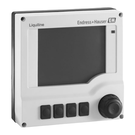
Liquiline
CM442R/CM444R/CM448R
Universal four-wire multichannel controller for
cabinet installation
These Instructions are Brief Operating Instructions; they are
not a substitute for the Operating Instructions pertaining to
the device.
Detailed information on the device can be found in the
Operating Instructions and in the other documentation
available at:
• www.endress.com/device-viewer
• Smart phone/tablet: Endress+Hauser Operations App
Solutions
Services
Advertisement
Table of Contents

Related Manuals for Endress+Hauser Liquiline CM442R


Summary of Contents for Endress+Hauser Liquiline CM442R
- Page 1 These Instructions are Brief Operating Instructions; they are not a substitute for the Operating Instructions pertaining to the device. Detailed information on the device can be found in the Operating Instructions and in the other documentation available at: • www.endress.com/device-viewer • Smart phone/tablet: Endress+Hauser Operations App...
- Page 2 Liquiline CM442R/CM444R/CM448R Order code 00X00-XXXX0XX0XXX Ser. No.: X000X000000 TAG No.: XXX000 Serial number www.endress.com/deviceviewer Endress+Hauser Operations App A0023555 Endress+Hauser...
-
Page 3: Table Of Contents
Liquiline CM442R/CM444R/CM448R Table of contents Table of contents Document information ............4 Warnings . -
Page 4: Document Information
Document information Liquiline CM442R/CM444R/CM448R Document information Warnings Structure of information Meaning This symbol alerts you to a dangerous situation. DANGER Failure to avoid the dangerous situation will result in a fatal or serious injury. Causes (/consequences) Consequences of non-compliance (if applicable) ‣... -
Page 5: Documentation
Liquiline CM442R/CM444R/CM448R Document information Documentation The following instructions complement these Brief Operating Instructions and are available on the product pages on the internet: • Operating Instructions for Liquiline CM44xR, BA01225C – Device description – Commissioning – Operation – Software description (without sensor menus, these are described in a separate manual, see below) –... -
Page 6: Basic Safety Instructions
Basic safety instructions Liquiline CM442R/CM444R/CM448R Basic safety instructions Requirements for the personnel • Installation, commissioning, operation and maintenance of the measuring system may be carried out only by specially trained technical personnel. • The technical personnel must be authorized by the plant operator to carry out the specified activities. -
Page 7: Occupational Safety
Liquiline CM442R/CM444R/CM448R Basic safety instructions 2.2.4 Installation environment The device and the associated power units can be operated with 24 V AC, 24 V DC or 100 to 230 V AC and provide shock protection in accordance with IP20. The components have been designed for pollution degree 2, and moisture must not be allowed to collect in them. -
Page 8: Product Safety
Basic safety instructions Liquiline CM442R/CM444R/CM448R Product safety 2.5.1 State of the art The product is designed to meet state-of-the-art safety requirements, has been tested, and left the factory in a condition in which it is safe to operate. The relevant regulations and European standards have been observed. -
Page 9: Incoming Acceptance And Product Identification
Liquiline CM442R/CM444R/CM448R Incoming acceptance and product identification Incoming acceptance and product identification Incoming acceptance Verify that the packaging is undamaged. Notify your supplier of any damage to the packaging. Keep the damaged packaging until the matter has been settled. -
Page 10: Scope Of Delivery
Incoming acceptance and product identification Liquiline CM442R/CM444R/CM448R 3.2.2 Product identification Product page www.endress.com/cm442r www.endress.com/cm444r www.endress.com/cm448r Interpreting the order code The order code and serial number of your product can be found in the following locations: • On the nameplate • In the delivery papers Obtaining information on the product Go to the product page for your product on the Internet. -
Page 11: Installation
Liquiline CM442R/CM444R/CM448R Installation 3.4.3 cETLus NI Cl. I, Div. 2 Only CM444R and CM448R • Conforms to UL STD 61010-1, ANSI/ISA STD 12.12.01, FM STD 3600 and FM STD 3611 • Certified to CSA STD C22.2 NO. 61010-1 and CSA STD C22.2 NO. 213 •... - Page 12 Installation Liquiline CM442R/CM444R/CM448R NOTICE Incorrect mounting location in the cabinet, spacing regulations not observed Possible malfunctions as a result of heat development and interference from neighboring devices ‣ Do not position the device directly above sources of heat. Make sure to observe the temperature specification.
- Page 13 Liquiline CM442R/CM444R/CM448R Installation 4.1.2 Wall mounting A0025370 2 Drilling pattern for wall mounting in mm (inch) Endress+Hauser...
- Page 14 Installation Liquiline CM442R/CM444R/CM448R 4.1.3 Mounting the external display The mounting plate also serves as the drilling template. The marks on the side help you mark the position of the drill holes. 140 (5.51) 105 (4.13) 4 x min. Ø 8 (0.31) min.
-
Page 15: Mounting The Measuring Device
Liquiline CM442R/CM444R/CM448R Installation Mounting the measuring device 4.2.1 DIN rail mounting The mounting procedure is the same for all Liquiline devices. The example shows a CM448R. In the order configuration, the securing clips are "tightened" to secure the DIN rail. - Page 16 Installation Liquiline CM442R/CM444R/CM448R Screw the housing onto the wall. 4.2.3 Mounting the optional external display CAUTION Sharp-edged, non-deburred drill holes Risk of injury, display cable may get damaged ‣ In particular, deburr the central drill hole for the display cable.
- Page 17 Liquiline CM442R/CM444R/CM448R Installation NOTICE Installation error Damage, e.g. to the cable, or malfunctions are possible ‣ Lay cables in such a way that they do not get squashed e.g. when closing the cabinet door. ‣ Plug the display cable only into the RJ45 socket in the base module.
-
Page 18: Post-Installation Check
Electrical connection Liquiline CM442R/CM444R/CM448R 4 Mounted display Post-installation check Following installation, check all devices (controller, power unit, display) for damage. Verify that the specified mounting distances have been observed. Verify that all securing clips have been snapped into place and that the components are securely positioned on the DIN rail. - Page 19 Liquiline CM442R/CM444R/CM448R Electrical connection NOTICE The device does not have a power switch ‣ The customer must provide a protected circuit breaker in the vicinity of the device. ‣ The circuit breaker must be a switch or power switch, and you must label it as the circuit breaker for the device.
- Page 20 Electrical connection Liquiline CM442R/CM444R/CM448R 5.1.2 Connecting the supply voltage for the CM442R – – – – – L / + N / – – A0025364 A0012404 5 Connecting power supply on the BASE-H or 6 Overall wiring diagram for BASE-H or -L...
- Page 21 Liquiline CM442R/CM444R/CM448R Electrical connection 5.1.3 Connecting the supply voltage for the CM444R and the CM448R – – – – + RD - BK – – Power L/+ N/– PE L/+ N/– A0015873 A0025365 8 Overall wiring diagram BASE-E and ...
-
Page 22: Connecting The Sensors
Electrical connection Liquiline CM442R/CM444R/CM448R Connecting the sensors 5.2.1 Sensor types with Memosens protocol Sensors with Memosens protocol Sensor types Sensor cable Sensors Digital sensors without With plug-in connection • pH sensors additional internal power and inductive signal • ORP sensors... - Page 23 Liquiline CM442R/CM444R/CM448R Electrical connection 5.2.2 Connecting the functional ground You must always connect the terminal strip with PE from the central node in the cabinet. Use the conductor with cable clamp that is included with the Memosens cable to connect the functional earth to the terminal strip of the device.
- Page 24 Electrical connection Liquiline CM442R/CM444R/CM448R Sensor Sensor A0023038 A0023039 10 sensors without additional supply voltage 11 sensors with additional supply voltage Sensor Sensor 1 Sensor 2 Sensor A0016197 12 sensors with and without additional supply voltage on 2DS sensor module...
-
Page 25: Connecting Additional Inputs, Outputs Or Relays
Liquiline CM442R/CM444R/CM448R Electrical connection Connecting additional inputs, outputs or relays WARNING Module not covered No shock protection. Danger of electric shock! ‣ If you are modifying or extending your hardware, always fill the slots from left to right. Do not leave any gaps. - Page 26 Electrical connection Liquiline CM442R/CM444R/CM448R 5.3.2 Current inputs Module 2AI – – 15 Module 16 Wiring diagram 5.3.3 Current outputs – – – – – – 17 Module 18 Wiring 19 Module 20 Wiring diagram...
-
Page 27: Connecting Digital Communication
Liquiline CM442R/CM444R/CM448R Electrical connection 5.3.4 Relay Module 2R Module 4R 24 Wiring 21 Module 22 Wiring 23 Module diagram diagram Connecting digital communication 5.4.1 Module 485 128/SW Service DGND 26 Wiring 25 Module diagram... - Page 28 Electrical connection Liquiline CM442R/CM444R/CM448R LEDs on front of module Description Color Description RJ45 LNK/ACT • Off = Connection is not active • On = Connection is active • Flashing = Data transmission RJ45 10/100 • Off = Transmission rate 10 MBit/s •...
- Page 29 Liquiline CM442R/CM444R/CM448R Electrical connection 5.4.2 ETH module 128/SW Service 28 Wiring 27 Module diagram LEDs on front of module Description Color Description RJ45 LNK/ACT • Off = Connection is not active • On = Connection is active • Flashing = Data transmission...
-
Page 30: Hardware Settings
Electrical connection Liquiline CM442R/CM444R/CM448R 5.4.3 Bus termination There are two ways to terminate the bus: 1. Internal terminating resistor (via DIP switch on the module board) "OFF" "ON" 29 DIP switches for internal terminating resistor ‣ Using a suitable tool, such as a tweezers, set all 4 DIP switches to the "ON" position. -
Page 31: Ensuring The Degree Of Protection
Liquiline CM442R/CM444R/CM448R Electrical connection Set the desired bus address via the DIP switches of module 485. For PROFIBUS DP, valid bus addresses are anything between 1 and 126, and anything between 1 and 247 for Modbus. If you configure an invalid address, software addressing is automatically enabled via the local configuration or via the fieldbus. -
Page 32: Post-Connection Check
Electrical connection Liquiline CM442R/CM444R/CM448R Post-connection check WARNING Connection errors The safety of people and of the measuring point is under threat. The manufacturer does not accept any responsibility for errors that result from failure to comply with the instructions in this manual. -
Page 33: Operation Options
Liquiline CM442R/CM444R/CM448R Operation options Operation options Overview 6.1.1 Display and operating elements (with optional display only) Outlet 1 11:09:15 29.01.2013 CH 1:1 pH 6.99 pH CH 1:1 Temperature 25.1 °C CH 1:2 Nitrate 9.02 mg/l CH 2:1 SAC 2.02 1/m... -
Page 34: Access To The Operating Menu Via The Local Display
Operation options Liquiline CM442R/CM444R/CM448R Access to the operating menu via the local display 6.2.1 Operating concept (with optional display) Pressing the soft key: selecting the menu directly Turning the navigator: moving the cursor in the menu Menu/Language Pressing the navigator: launching a function Turning the navigator: selecting a value (e.g. -
Page 35: Commissioning
Liquiline CM442R/CM444R/CM448R Commissioning 6.2.2 Locking or unlocking operating keys Locking operating keys Press the navigator for longer than 2 s. A context menu for locking the operating keys is displayed. You have the choice of locking the keys with or without password protection. "With password"... -
Page 36: Basic Setup
Commissioning Liquiline CM442R/CM444R/CM448R 7.2.1 Setting the operating language Configure language If you have not already done so, close the housing cover and screw the device closed. Switch on the supply voltage. Wait for initialization. Press the soft key MENU. Set your language in the top menu item. - Page 40 www.addresses.endress.com...
Need help?
Do you have a question about the Liquiline CM442R and is the answer not in the manual?
Questions and answers