Endress+Hauser Liquiline CM442R Brief Operating Instructions
Universal four-wire multichannel controller for cabinet installation
Hide thumbs
Also See for Liquiline CM442R:
- Operating instructions manual (172 pages) ,
- Technical information (52 pages) ,
- Brief operating instructions (40 pages)
Table of Contents
Advertisement
Quick Links
KA01160C/07/EN/08.21
71519572
2021-03-04
Products
Brief Operating Instructions
Liquiline
CM442R/CM444R/CM448R
Universal four-wire multichannel controller for
cabinet installation
These instructions are Brief Operating Instructions; they are
not a substitute for the Operating Instructions pertaining to
the device.
Detailed information on the device can be found in the
Operating Instructions and in the other documentation
available at:
• www.endress.com/device-viewer
• Smart phone/tablet: Endress+Hauser Operations App
Solutions
Services
Advertisement
Table of Contents

Related Manuals for Endress+Hauser Liquiline CM442R


Summary of Contents for Endress+Hauser Liquiline CM442R
- Page 1 These instructions are Brief Operating Instructions; they are not a substitute for the Operating Instructions pertaining to the device. Detailed information on the device can be found in the Operating Instructions and in the other documentation available at: • www.endress.com/device-viewer • Smart phone/tablet: Endress+Hauser Operations App...
- Page 2 Liquiline CM442R/CM444R/CM448R Order code: XXXXX-XXXXXX Ser. no.: XXXXXXXXXXXX Ext. ord. cd.: XXX.XXXX.XX Serial number www.endress.com/deviceviewer Endress+Hauser Operations App A0040778 Endress+Hauser...
-
Page 3: Table Of Contents
Liquiline CM442R/CM444R/CM448R Table of contents Table of contents About this document ............. . 4 Warnings . -
Page 4: About This Document
About this document Liquiline CM442R/CM444R/CM448R About this document Warnings Structure of information Meaning This symbol alerts you to a dangerous situation. DANGER Failure to avoid the dangerous situation will result in a fatal or serious injury. Causes (/consequences) If necessary, Consequences of non- compliance (if applicable) ‣... -
Page 5: Symbols On The Device
Liquiline CM442R/CM444R/CM448R About this document Symbols on the device Symbol Meaning Reference to device documentation Documentation The following instructions complement these Brief Operating Instructions and are available on the product pages on the Internet: • Operating Instructions Liquiline CM44xR, BA01225C •... -
Page 6: Basic Safety Instructions
Basic safety instructions Liquiline CM442R/CM444R/CM448R Basic safety instructions Requirements for personnel • Installation, commissioning, operation and maintenance of the measuring system may be carried out only by specially trained technical personnel. • The technical personnel must be authorized by the plant operator to carry out the specified activities. -
Page 7: Workplace Safety
Liquiline CM442R/CM444R/CM448R Basic safety instructions 2.2.4 Non-designated use and improper use NOTICE Objects stored on top of the housing May cause short-circuits or fire or result in the failure of individual cabinet components or complete failure of the measuring point! ‣... - Page 8 Basic safety instructions Liquiline CM442R/CM444R/CM448R CAUTION Cleaning not switched off during calibration or maintenance activities Risk of injury due to medium or cleaning agent! ‣ If a cleaning system is connected, switch it off before removing a sensor from the medium.
-
Page 9: Product Safety
Liquiline CM442R/CM444R/CM448R Basic safety instructions Product safety 2.5.1 State-of-the-art technology The product is designed to meet state-of-the-art safety requirements, has been tested, and left the factory in a condition in which it is safe to operate. The relevant regulations and international standards have been observed. -
Page 10: Incoming Acceptance And Product Identification
Incoming acceptance and product identification Liquiline CM442R/CM444R/CM448R Incoming acceptance and product identification Incoming acceptance Verify that the packaging is undamaged. Notify the supplier of any damage to the packaging. Keep the damaged packaging until the issue has been resolved. -
Page 11: Scope Of Delivery
A new window (Device Viewer) opens. All of the information relating to your device is displayed in this window as well as the product documentation. 3.2.3 Manufacturer's address Endress+Hauser Conducta GmbH+Co. KG Dieselstraße 24 D-70839 Gerlingen Scope of delivery The scope of delivery comprises: •... -
Page 12: Installation
Installation Liquiline CM442R/CM444R/CM448R Installation Installation conditions 4.1.1 Mounting on DIN rail as per IEC 60715 CAUTION The power unit can get very hot under full load Burn hazard! ‣ Avoid touching the power unit during operation. ‣ The minimum distances to other devices must be observed. - Page 13 Liquiline CM442R/CM444R/CM448R Installation The following minimum clearance specifications must be observed: • Distances at the side in relation to other devices incl. power units and to the wall of the cabinet: at least 20 mm (0.79 inch) • Distance above and below the device and depth distance (to control cabinet door or other devices installed there): at least 50 mm (1.97 inch)
- Page 14 Installation Liquiline CM442R/CM444R/CM448R 4.1.3 Mounting the external display The mounting plate also serves as the drilling template. The marks on the side help you mark the position of the drill holes. 140 (5.51) 105 (4.13) 4 x min. Ø 8 (0.31) min.
-
Page 15: Mounting The Measuring Device
Liquiline CM442R/CM444R/CM448R Installation 4.1.4 Cable length for optional display Length of display cable provided: 3 m (10 ft) Maximum permitted length of a display cable: 5 m (16.5 ft) Mounting the measuring device 4.2.1 DIN rail mounting The mounting procedure is the same for all Liquiline devices. The example shows a CM448R. - Page 16 Installation Liquiline CM442R/CM444R/CM448R 4.2.2 Wall mounting Mounting material (screws, dowels) are not included in the scope of delivery and must be provided by the customer. CM444R and CM448R: The external power unit can be mounted on a DIN rail only.
- Page 17 Liquiline CM442R/CM444R/CM448R Installation 4 x Ø 8 (0.31) Ø 20 (0.79) Draw lines to interconnect all the marks. This will indicate the position of the five drill holes needed. Drill the holes (→ 3, 14). Pull the display cable through the hole in the middle, and place the display from the outside through the four holes drilled for this purpose, ensuring that the torx screws have been unscrewed to the last half turn but are still in place.
-
Page 18: Post-Installation Check
Installation Liquiline CM442R/CM444R/CM448R Place the mounting plate on the inside over the screws (a), slide it down (b) and tighten the screws (c). The display is now mounted and ready to use. 4 Mounted display NOTICE Incorrect installation Damage, e.g. -
Page 19: Electrical Connection
Liquiline CM442R/CM444R/CM448R Electrical connection Verify that the specified installation clearances have been observed. Verify that all securing clips have been snapped into place and that the components are securely positioned on the DIN rail. Ensure that the temperature limits are observed at the mounting location. - Page 20 Electrical connection Liquiline CM442R/CM444R/CM448R 5.1.1 Cable terminals Plug-in terminals for Memosens and PROFIBUS/RS485 connections ‣ ‣ Insert the cable until the limit stop. ‣ Press the screwdriver against the Remove the screwdriver (closes the clip (opens the terminal). terminal). After connection, make sure that every cable end is securely in place. Terminated cable ends, in particular, tend to come loose easily if they have not been correctly inserted as far as the limit stop.
- Page 21 Liquiline CM442R/CM444R/CM448R Electrical connection 5.1.2 Connecting the supply voltage for CM442R – – – – – N/– – A0039665 A0039625 5 Connecting power supply on the BASE2-H 6 Overall wiring diagram for BASE2-H or -L or -L Power unit 100 to 230 VAC...
- Page 22 Electrical connection Liquiline CM442R/CM444R/CM448R 5.1.3 Connecting the supply voltage for CM444R and the CM448R – – – – + RD - BK – – Power L/+ N/– PE L/+ N/– * A0039624 A0039668 8 Overall wiring diagram for BASE2-E and ...
-
Page 23: Connecting The Sensors
Liquiline CM442R/CM444R/CM448R Electrical connection Connecting the sensors 5.2.1 Sensor types with Memosens protocol for non-hazardous area Sensors with Memosens protocol Sensor types Sensor cable Sensors Digital sensors without With plug-in • pH sensors additional internal power connection and • ORP sensors... - Page 24 Electrical connection Liquiline CM442R/CM444R/CM448R 5.2.2 Sensor types with Memosens protocol for hazardous area Sensors with Memosens protocol Sensor types Sensor cable Sensors Digital sensors without With plug-in connection • pH sensors additional internal power supply and inductive signal • ORP sensors transmission •...
- Page 25 Liquiline CM442R/CM444R/CM448R Electrical connection 5.2.4 Connecting the functional ground You must always connect the terminal strip with PE from the central node in the cabinet. Use the conductor with cable clamp that is included with the Memosens cable to connect the functional earth to the terminal strip of the device.
- Page 26 Electrical connection Liquiline CM442R/CM444R/CM448R Sensor Sensor A0039629 A0039622 10 sensors without additional supply voltage 11 sensors with additional supply voltage Sensor Sensor 1 Sensor 2 Sensor A0033206 12 sensors with and without additional supply voltage at sensor module 2DS 5.2.6...
-
Page 27: Connecting Additional Inputs, Outputs Or Relays
Liquiline CM442R/CM444R/CM448R Electrical connection 2DS Ex-i Sensor Sensor A0045345 13 Sensors without additional supply voltage connected to sensor communication module type 2DS Ex-i Intrinsically safe sensors for use in explosive atmospheres may only be connected to the sensor communication module type 2DS Ex-i. Only the sensors covered by the certificates may be connected (see XA). - Page 28 Electrical connection Liquiline CM442R/CM444R/CM448R 5.3.1 Digital inputs and outputs Module DIO – – – – – – 14 Module 15 Wiring diagram 5.3.2 Current inputs Module 2AI – – 16 Module 17 Wiring diagram Endress+Hauser...
- Page 29 Liquiline CM442R/CM444R/CM448R Electrical connection 5.3.3 Current outputs – – – – – – 18 Module 19 Wiring 20 Module 21 Wiring diagram diagram 5.3.4 Relays Module 2R Module 4R 25 Wiring 22 Module 23 Wiring ...
-
Page 30: Connecting Profibus Or Modbus 485
Electrical connection Liquiline CM442R/CM444R/CM448R Connecting PROFIBUS or Modbus 485 5.4.1 Module 485 128/SW Service DGND Termi- nation RS485 27 Wiring 26 Module diagram Terminal PROFIBUS DP Modbus RS485 Not connected DGND DGND Endress+Hauser... - Page 31 Liquiline CM442R/CM444R/CM448R Electrical connection LEDs on front of module Designation Color Description RJ45 LNK/ACT • Off = Connection is not active • On = Connection is active • Flashing = Data transmission RJ45 10/100 • Off = Transmission rate 10 MBit/s •...
-
Page 32: Hardware Settings
Electrical connection Liquiline CM442R/CM444R/CM448R 5.4.2 Bus termination There are 2 ways to terminate the bus: 1. Internal termination (via DIP switch on module board) "OFF" "ON" 28 DIP switch for internal termination ‣ Using a suitable tool such as a tweezer, move all four DIP switches to the "ON" position. -
Page 33: Ensuring The Degree Of Protection
Liquiline CM442R/CM444R/CM448R Electrical connection Set the desired bus address via the DIP switches of module 485. For PROFIBUS DP, valid bus addresses are anything between 1 and 126, and anything between 1 and 247 for Modbus. If you configure an invalid address, software addressing is automatically enabled via the local configuration or via the fieldbus. -
Page 34: Post-Connection Check
Electrical connection Liquiline CM442R/CM444R/CM448R Post-connection check WARNING Connection errors The safety of people and of the measuring point is at risk! The manufacturer does not accept any responsibility for errors that result from failure to comply with the instructions in this manual. -
Page 35: Operation Options
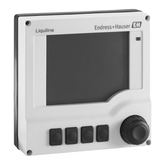
Liquiline CM442R/CM444R/CM448R Operation options Operation options Overview 6.1.1 Display and operating elements (only with optional display) Outlet 1 11:09:15 29.01.2013 CH 1:1 pH 6.99 pH CH 1:1 Temperature 25.1 °C CH 1:2 Nitrate 9.02 mg/l CH 2:1 SAC 2.02 1/m... -
Page 36: Access To The Operating Menu Via The Local Display
Operation options Liquiline CM442R/CM444R/CM448R Access to the operating menu via the local display 6.2.1 Operating concept (with optional display) ‣ ‣ Pressing the soft key: selecting the menu directly Turning the navigator: moving the cursor in the menu Menu/Language ‣... -
Page 37: Commissioning
Liquiline CM442R/CM444R/CM448R Commissioning 6.2.2 Locking or unlocking operating keys Locking operating keys Press the navigator for longer than 2 s. A context menu for locking the operating keys is displayed. You have the choice of locking the keys with or without password protection. "With password"... -
Page 38: Basic Setup
Commissioning Liquiline CM442R/CM444R/CM448R 7.2.1 Setting the operating language Configuring the language Switch on the supply voltage. Wait for the initialization to finish. Press the soft key MENU . Set your language in the top menu item. The device can now be operated in your chosen language. - Page 40 *71519572* 71519572 www.addresses.endress.com...
Need help?
Do you have a question about the Liquiline CM442R and is the answer not in the manual?
Questions and answers