
Related Manuals for TDK-Lambda THR4


Summary of Contents for TDK-Lambda THR4
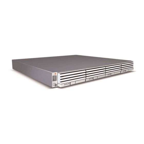
- Page 1 THR4 Installation, Operation, and Maintenance Manual THR4 THR400 August 2009 Version A4 This datasheet has been downloaded from http://www.digchip.com at this page...
-
Page 2: Table Of Contents
THR4-S S ERIES POWER SYSTEM Table of Contents 1) Safety and Recommended Practices General practices FCC Compliance Statement Warning 2) Product Section Power Module Specification DC Output Voltage 2.1.1 Heat Dissipation 2.1.2 AC input Voltage Requirements AC Input Voltage 2.2.1 AC Input Wire Diagrams 2.2.2... -
Page 3: Safety And Recommended Practices
THR4-S S ERIES POWER SYSTEM 1 Safety and Recommended Practices 1.1 General practices For use in restricted access locations only. Suitable for mounting on concrete or other non-combustible surfaces This product accepts a nominal AC Voltage For hard-wired AC connections, a readily... -
Page 4: Fcc Compliance Statement
THR4-S S ERIES POWER SYSTEM 1.2 FCC Compliance Statement Note: This device complies with Part 15 of FCC Rules. Operation is subject to the following two conditions: 1. This device may not cause harmful interference, and 2. This device must accept any interference received, including interference that may cause undesired operation. -
Page 5: Product Section
THR4-S S ERIES POWER SYSTEM 2 Product Section 2.1 Power Module Specification 2.1.1 DC Output Voltage Table 1 shows the DC voltage range and max current for each model of power module for this system. DC Output Voltage Model Voltage min/max... -
Page 6: Ac Input Voltage
THR4-S S ERIES POWER SYSTEM 2.2 AC Input Requirement 2.2.1 AC Input Voltage Table 3 shows the required AC input voltages for the available power modules. The power mod- ules under wide line (WL) can be connected to a nominal input voltage between 100 V & 240V. -
Page 7: Ac Current And Cable Sizing
THR4-S S ERIES POWER SYSTEM 2.2.2.2 Individual feed A system with an individual feed AC architecture feeds each power module slot with an AC feed. There are two different styles of individual feeds for this system. The first style of connection is made via rear accessed compression style terminal blocks see Figure 6. - Page 8 THR4-S S ERIES POWER SYSTEM For this example we will assume that future growth is necessary so we will size the AC feed for four power modules. Using Table 4, each AC feed, to the pair of TH120048, power modules will require will require a 20 amp breaker with 12 AWG wire, at high line, per feed.
-
Page 9: Circuit Drawings
Each system is equipped with 2 unprotected bulk output connections; one set located on each side of the rear of the shelf. The THR4 rack will only accept lugs and THR400 will accept lugs or bus bars. Unprotected bulk connections are double, ¼"-20 (M6) studs with 5/8" centers. The maximum tongue width for bulk connections is 0.67". -
Page 10: Dc Lug Requirements
THR4-S S ERIES POWER SYSTEM The National Electric Code table 310.16 provides ampacity values for various sizes, bundles, and insulation temperature rated wire. ALWAYS FOLLOW NEC RULES AND YOUR LOCAL COMPANY PRACTICES WHEN SELECTING DC WIRING AND PROTECTION. Table 5 shows recommended wire sizes. -
Page 11: Required Tools
THR4-S S ERIES POWER SYSTEM 2.4 Torque Settings Table 7 shows recommended torque settings for all mechanical and electrical connections accord- ing to screw or nut size. Recommended Torque Settings Screw or Nut Size Torque (in-lbs) 4-40 6-32 8-32 10-32 12-24 ¼-20/M6... -
Page 12: Ac Input
THR4-S S ERIES POWER SYSTEM Mounting brackets Figure 4 - Mounting brackets 5.2 AC input 5.2.1 Dual feed with terminal blocks Remove safety cover over the terminal block shown in Figure 5. Feed AC wires through hole on terminal block cover and connect wires from AC cord into appropriate positions labeled in Figure 6. -
Page 13: Individual Feed With Terminal Blocks
AC Receptacle 3 AC Receptacle 2 AC Receptacle 1 Figure 8 - Rear View (IEC320 AC Connections) (THR4) 5.2.4 AC Cord Brackets Optional brackets are available to secure the IEC320 plugs to the shelf on an individual feed sys- tem. Follow the instructions below for using these brackets. -
Page 14: Dc Output
5.3 DC Output DC connections are accomplished via the two rear bulk output connection as shown in Figure 11 (THR4) & Figure 12 (THR400). Torque connections according to Table 7. DO NOT exceed the current rating of the shelf from section 2.3. -
Page 15: Circuit
"-" for negative. A DC reference ground should be connected to the appropriate output for desired polarity of the system. Repeat connections for the other side. Plastic knockouts Figure 11 - DC output connections (THR4) 5.3.2 Circuit 23 Connect lugged wires or bus bars to the rear accessed bulk outputs. Verify polarity of connec- tions before power units on. -
Page 16: Nic Interface
THR4-S S ERIES POWER SYSTEM Alarm Connection NIC connections RJ45/RS232 Figure 13 - Alarm Connection 5.5 NIC interface (optional) An optional NIC interface is available. The Nic card has a 10/100 baseT (RJ45) connection in the front of the shelf with a RS232 (RJ45) in the rear. Follow directions in NIC "Quick Start Guide". -
Page 17: Test And Turn-U U P
THR4-S S ERIES POWER SYSTEM 6 Test and Turn-U U p 6.1 Power Up Once all AC and DC connections have been secured and checked, install each power module sequentially by sliding and latching each power module into a rack position as shown in Figure 17. - Page 18 THR4-S S ERIES POWER SYSTEM Alarm connection Pin 1 Figure 15 - Alarm Connection Pin 11 Pin 20 Pin 11 Pin 20 Pin 1 Pin 10 Figure 16 - Alarm cable pin out (TLRC01) Page. 18 Revision A4 : August, 2009...
-
Page 19: Replacement Items
THR4-S S ERIES POWER SYSTEM Alarm and Signal Interconnections Wire Description Pin Color Shelf Bias: A regulated 12V/100ma bias supply. Referenced to Pin 10. SCL: I C clock line. Referenced to Pin 10. RED/WHT SDA: I C clock line. Referenced to Pin 10. -
Page 20: Troubleshooting
THR4-S S ERIES POWER SYSTEM Latch Handle Latch Button Figure 17 - Power Module Removal 9 Troubleshooting 9.1 Problems and Solutions The modular, plug-n-play nature of this plant makes diagnostics and repair very easy. Make sure that all power modules are properly seated and latched into their respective slots. Make sure that all power and signal connectors are properly mated. -
Page 21: Nic Information
THR4-S S ERIES POWER SYSTEM Figure 18 - Short Circuit & Current Limit 10 NIC Information (Optional) An optional NIC is available for additional control of the system. You can connect a computer to the NIC card via a straight through patch cable through a hub or router, or via a crossover cable for direct connection. - Page 22 THR4-S S ERIES POWER SYSTEM Controller Settings System Description Parameters Nominal Nominal Nominal Nominal Plant Settings Float Voltage The voltage to which the power modules will regulate the plant voltage during float mode (Volts) 13.5 Vdc 27 Vdc 54 Vdc...
-
Page 23: Circuit
THR4-S S ERIES POWER SYSTEM Controller Settings System Description Parameters Nominal Nominal Nominal Nominal Battery Boost Start Modes Current Delay The amount of time the start current must be exceeded before the test will start. (Minutes) 0 minutes 0 minutes 0 minutes... -
Page 24: Nic Card Replacement
THR4-S S ERIES POWER SYSTEM 10.2 NIC Card Replacement In the event the NIC card needs to be replaced, the system will remain at the last known settings until a new card is installed. To replace the NIC card, loosen the set screw and slide the NIC card out of the shelf.
Need help?
Do you have a question about the THR4 and is the answer not in the manual?
Questions and answers