
Related Manuals for Daikin VRV FXMA200AXVMB


Summary of Contents for Daikin VRV FXMA200AXVMB
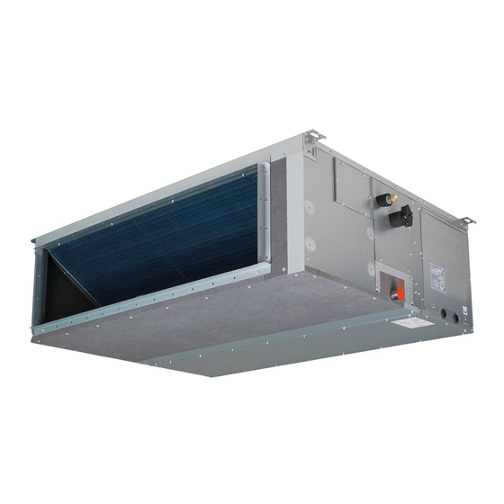
- Page 1 Installation and operation manual VRV system air conditioner Installation and operation manual FXMA200AXVMB English VRV system air conditioner FXMA250AXVMB...
- Page 2 4P689940-1...
- Page 3 4P689940-2...
-
Page 4: Table Of Contents
Daikin website (publicly accessible). 13.2 Connecting the refrigerant piping ..........17 ▪ The full set of latest technical data is available on the Daikin 13.2.1 To connect the refrigerant piping to the indoor unit ..17 Business Portal (authentication required). - Page 5 Make sure installation, servicing, maintenance, repair and unit. Refer to the technical datasheet of your model for applied materials follow the instructions from Daikin and, in the setting range. addition, comply with applicable legislation and are ▪...
-
Page 6: Instructions For Equipment Using R32 Refrigerant
A phase advancing capacitor will reduce performance and may Make sure installation, servicing, maintenance and repair cause accidents. comply with instructions from Daikin and with applicable legislation and are executed ONLY by authorised persons. WARNING CAUTION Use an all-pole disconnection type breaker with at least 3 ... -
Page 7: Installation Space Requirements
3 User safety instructions CAUTION WARNING ▪ Incomplete flaring may cause refrigerant gas leakage. This appliance contains R32 refrigerant. For the minimum floor area of the room in which the appliance is stored refer ▪ Do NOT re-use flares. Use new flares to prevent to installation and operation manual of the outdoor unit. -
Page 8: Instructions For Safe Operation
3 User safety instructions Instructions for safe operation CAUTION To avoid oxygen deficiency, ventilate WARNING the room sufficiently if equipment with ▪ Do NOT modify, disassemble, burner is used together with the remove, reinstall or repair the unit system. yourself as incorrect dismantling or installation may cause an electrical CAUTION shock or fire. - Page 9 3 User safety instructions CAUTION ▪ Do NOT use cleaning materials or means to accelerate the defrosting After a long use, check the unit stand process other than those and fitting for damage. If damaged, the recommended by the manufacturer. unit may fall and result in injury.
-
Page 10: About The System
4 About the system About the system User interface WARNING CAUTION ▪ Do NOT modify, disassemble, remove, reinstall or ▪ NEVER touch the internal parts of the controller. repair the unit yourself as incorrect dismantling or ▪ Do NOT remove the front panel. Some parts inside are installation may cause an electrical shock or fire. -
Page 11: Special Heating Operation Modes
7 Maintenance and service Icon Operation mode NOTICE Fan only. In this mode, air circulates without heating Do NOT wipe the controller operation panel with benzine, or cooling. thinner, chemical dust cloth, etc. The panel may get discoloured or the coating peeled off. If it is heavily dirty, Auto. -
Page 12: To Clean The Air Outlet
7 Maintenance and service 1 Remove the air filter (composed of 3 equal parts). For the WARNING removal procedure 8 mm pre-filter refer to the reference guide ▪ Do NOT pierce or burn refrigerant cycle parts. of the indoor unit. For other air filter types refer to the installation manual of the filter chamber. -
Page 13: Troubleshooting
Refer reference guide located https:// of the user interface. www.daikin.eu for more troubleshooting tips. Use the search function to find your model. If after checking all above items, it is impossible to fix the problem Troubleshooting yourself, contact your installer and state the symptoms, the complete... -
Page 14: Installation Site Requirements Of The Indoor Unit
12 Unit installation Floor surface 12.1.1 Installation site requirements of the Maintenance space indoor unit Minimum required space of installation Minimum space for allowing downward slope 1/100 for Minimum floor area requirements drainage ▪ Discharge grille. Minimum requirement installation height of CAUTION discharge grille ≥1.8 m. -
Page 15: Guidelines When Installing The Ducting
For installation of the optional output PCB or the optional 8 mm pre-filter see the reference guide located on https:// 6 Connect the duct to the canvas duct on both sides. www.daikin.eu. Use the search function to find your 7 Wind aluminium tape around the flanges and duct connections. model. -
Page 16: Guidelines When Installing The Drain Piping
12 Unit installation Canvas duct (field supply) 3 Push the drain hose as far as possible over the adapter for the Aluminium tape (field supply) drain hose. ▪ Filter. Be sure to attach an air filter inside the air passage on the 4 Tighten the metal clamp until the screw head is less than 4 mm air inlet side. -
Page 17: Piping Installation
13 Piping installation Refrigerant pipes Pipe outer diameter Insulation inner Insulation thickness (Ø diameter (Ø 5 Turn OFF the power. 9.5 mm (3/8") 10~14 mm ≥13 mm 6 Disconnect the electrical wiring. 19.1 mm (3/4") 20~24 mm ≥13 mm ▪ Remove the service cover. ▪ Disconnect the power supply. Ø... -
Page 18: Electrical Installation
14 Electrical installation NOTICE 14.1 Specifications of standard wiring ▪ Join the attached piping (accessory) and the field components refrigerant piping (field supply) by brazing before fixing the attached piping to the unit. Component Class ▪ Do NOT braze the refrigerant piping directly to the indoor unit. -
Page 19: Commissioning
Next cable clamp. commissioning instructions in this chapter, a general commissioning checklist is also available on the Daikin Business Portal (authentication required). The general commissioning checklist is complementary to the instructions in this chapter and can be used as a guideline and reporting template during the commissioning and hand-over to the user. -
Page 20: To Perform A Test Run
16 Configuration Setting: External static pressure Fuses, circuit breakers, or protection devices Check that the fuses, circuit breakers, or the locally INFORMATION installed protection devices are of the size and type ▪ The fan speed of the indoor unit is preset to ensure the installation" ... - Page 21 16 Configuration Setting: Thermostat sensor selection — External static pressure (Pa) This setting must correspond with how/if the remote controller 13(23) thermostat sensor is used. When the remote controller thermostat Then sensor is… — Used in combination with indoor unit 10 (20) thermistor Not used (indoor unit thermistor only)
-
Page 22: Technical Data
▪ A subset of the latest technical data is available on the regional Daikin website (publicly accessible). Connector (frame ground) ▪ The full set of latest technical data is available on the Daikin Harness Business Portal (authentication required). H*P, LED*, V*L... - Page 23 17 Technical data Symbol Meaning Compressor motor Fan motor Drain pump motor Swing motor MR*, MRCW*, MRM*, MRN* Magnetic relay Neutral n=*, N=* Number of passes through ferrite core Pulse-amplitude modulation PCB* Printed circuit board Power module Switching power supply PTC* PTC thermistor Insulated gate bipolar transistor...
- Page 24 3P688304-1 2022.03 Verantwortung für Energie und Umwelt...
Need help?
Do you have a question about the VRV FXMA200AXVMB and is the answer not in the manual?
Questions and answers