Table of Contents
Advertisement
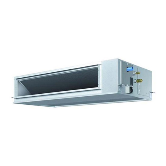
SYSTEM Inverter Air Conditioners
MODELS
Ceiling-mounted Duct type
FXMQ20PVE
FXMQ40PVE
FXMQ25PVE
FXMQ50PVE
FXMQ32PVE
FXMQ63PVE
READ THESE INSTRUCTIONS CAREFULLY BEFORE INSTALLATION.
KEEP THIS MANUAL IN A HANDY PLACE FOR FUTURE REFERENCE.
LESEN SIE DIESE ANWEISUNGEN VOR DER INSTALLATION SORGFÄLTIG DURCH.
BEWAHREN SIE DIESE ANLEITUNG FÜR SPÄTERE BEZUGNAHME GRIFFBEREIT AUF.
LIRE SOIGNEUSEMENT CES INSTRUCTIONS AVANT L'INSTALLATION.
CONSERVER CE MANUEL A PORTEE DE MAIN POUR REFERENCE ULTERIEURE.
LEA CUIDADOSAMENTE ESTAS INSTRUCCIONES ANTES DE INSTALAR.
GUARDE ESTE MANUAL EN UN LUGAR A MANO PARA LEER EN CASO DE TENER
ALGUNA DUDA.
PRIMA DELL'INSTALLAZIONE LEGGERE ATTENTAMENTE QUESTE ISTRUZIONI.
TENERE QUESTO MANUALE A PORTATA DI MANO PER RIFERIMENTI FUTURI.
ÄΙΑΒΑΣΤΕ ΠΡΟΣΕΚΤΙΚΑ ΑΥΤΕΣ ΤΙΣ ΟÄΗΓΙΕΣ ΠΡΙΝ ΑΠΟ ΤΗΝ ΕΓΚΑΤΑΣΤΑΣΗ ΕΧΕΤΕ ΑΥΤΟ
ΤΟ ΕΓΧΕΙΡΙÄΙΟ ΕΥΚΑΙΡΟ ΓΙΑ ΝΑ ΤΟ ΣΥΜΒΟΥΛΕΥΕΣΤΕ ΣΤΟ ΜΕΛΛΟΝ.
LEES DEZE INSTRUCTIES ZORGVULDIG DOOR VOOR INSTALLATIE. BEWAAR DEZE HAN-
DLEINDING WAAR U HEM KUNT TERUGVINDEN VOOR LATERE NASLAG.
LEIA COM ATENÇÃO ESTAS INSTRUÇÕES ANTES DE REALIZAR A INSTALAÇÃO.
MANTENHA ESTE MANUAL AO SEU ALCANCE PARA FUTURAS CONSULTAS.
ПЕРЕД НАЧАЛОМ МОНТАЖА ВНИМАТЕЛЬНО ОЗНАКОМЬТЕСЬ С ДАННЫМИ
ИНСТРУКЦИЯМИ. СОХРАНИТЕ ДАННОЕ РУКОВОДСТВО В МЕСТЕ, УДОБНОМ ДЛЯ
ОБРАЩЕНИЯ В БУДУЩЕМ.
INSTALLATION MANUAL
FXMQ80PVE
FXMQ140PVE
FXMQ100PVE
FXMQ125PVE
English
Deutsch
Français
Español
Italiano
ëëçíéêÜ
Nederlands
Portugues
óññêèé
Advertisement
Table of Contents

Related Manuals for Daikin FXMQ20PVE


Summary of Contents for Daikin FXMQ20PVE
-
Page 1: Installation Manual
INSTALLATION MANUAL English SYSTEM Inverter Air Conditioners Deutsch MODELS Français Ceiling-mounted Duct type FXMQ20PVE FXMQ40PVE FXMQ80PVE FXMQ140PVE Español FXMQ25PVE FXMQ50PVE FXMQ100PVE FXMQ32PVE FXMQ63PVE FXMQ125PVE Italiano ëëçíéêÜ READ THESE INSTRUCTIONS CAREFULLY BEFORE INSTALLATION. KEEP THIS MANUAL IN A HANDY PLACE FOR FUTURE REFERENCE. - Page 2 3P223078-1A...
-
Page 3: Table Of Contents
VRV SYSTEM Inverter Air Conditioners Installation manual CONTENTS • Be sure to use only the specified accessories and parts for installation work. 1. SAFETY PRECAUTIONS..........1 Failure to use the specified parts may result in the unit falling, 2. BEFORE INSTALLATION ..........2 water leakage, electric shocks or fire. -
Page 4: Before Installation
• Do not install the air conditioner in the following locations: PRECAUTIONS 1. Where there is a high concentration of mineral oil spray or • Be sure to read this manual before installing the indoor unit. vapour (e.g. a kitchen). •... -
Page 5: Selecting Installation Site
b. Items to be checked at time of delivery Wire fixing Wire fixing Items to be checked Check Name Washer (11) bracket (12) screw (13) (Other) Are you sure the control box lid, air filter, air inlet grille, and • Operation Quantity 8 pcs. -
Page 6: Preparations Before Installation
• In the case of the installation of a wireless remote controller, Case 2, 3 the transmission distance of the wireless remote controller may Inspection hatch be shortened if the room has a fluorescent light of electronic Control box (Ceiling opening) lighting type (i.e., an inverter or rapid-start fluorescent light). -
Page 7: Indoor Unit Installation
INDOOR UNIT INSTALLATION CAUTION 〈It may be easier to install accessories (sold separately) • Use the level and check that the unit is installed horizontally. before installing the indoor unit. Refer to the installation (4-directions) manuals provided to the accessories as well.〉 •... - Page 8 • Refer to Table 2 for the processing dimensions of the (3) Refer to the illustration on the right-hand side and be sure to flare. perform heat insulation work on the piping joints after gas • Use the flare nut provided with the unit. leakage checks.
-
Page 9: Drain Piping Work
• Perform nitrogen substituent or apply nitrogen into the • Be sure to use the drain hose (2) and metal clamp (1). refrigerant piping (see NOTE 1) in the case of refrigerant Insert the drain hose (2) deep into the base of the piping blazing (see NOTE 2). -
Page 10: Duct Work
(2) Check the smooth draining of the piping on completion of Drain soket the installation of the piping. Drain pan Water inlet [Before electrical work] Refrigerant piping CAUTION Control box lid • A licensed electrical engineering technician must con- duct electrical wiring work (including grounding work). Control box •... -
Page 11: Electric Wiring Work
Voltage (3). Model Volts range • Wrap aluminum tape around the flange and duct joint in order to prevent air leakage. FXMQ20PVE 0.09 FXMQ25PVE 0.09 Flange on air inlet side Flange on air outlet side (provided with the unit) (provided with the unit) FXMQ32PVE 0.09... -
Page 12: Wiring Example And How To Set The Remote Controller
(3) Follow the instructions below, and lay the wires in the con- NOTE trol box. 1. Shows only in case of protected pipes. Use H07RN-F in case of no protection. Fix the wires with 2. Vinyl cord with sheath or cable (Insulated thickness : 1mm clamp (8) to the or more) Transmission... - Page 13 (5) Mount the provided wire fixing bracket (12) with the wire fix- No. 1 system: When using 1 remote controller for 1 indoor ing screw (13). Fix each wire with the provided clamp (8). unit Transmission wiring Power supply Power supply Power supply Remote controller wiring single phase...
-
Page 14: Field Setting
No. 3 system: When including BS unit (2) Set the main/sub switch on one of the remote controller PCBs to sub. (Keep the switch of the other remote controller Power supply PCB set to main.) single phase 50Hz 220-240V single phase (Factory setting) Outdoor unit BS unit... - Page 15 1. Settings for Optional Accessories • Consult your Daikin representative if there is any change in • In the case of connecting optional accessories, refer to the ventilation paths (e.g., the duct and air outlet) after the...
-
Page 16: Test Operation
Table 5 Table 7 External Static FIRST SECOND Remote controller display Contents MODE NO. Pressure CODE NO. CODE NO. Error in power supply voltage to “A8” lit 30Pa (*1)(*4) indoor unit. Fan driver PCB of indoor unit ↔ 50Pa “C1” lit indoor control PCB transmission 60Pa error. - Page 17 3PN06583-7N EM07A049D (0904) HT...
Need help?
Do you have a question about the FXMQ20PVE and is the answer not in the manual?
Questions and answers