Advertisement

AQ DCV
INSTALLATION AND USER GUIDE
AQSQDCV1
AQSQDCV2
AQRNDCV1
AQRNDCV2

Advertisement

Table of Contents
loading
Need help?

Need help?

Do you have a question about the AQRNDCV1 and is the answer not in the manual?

Questions and answers

Subscribe to Our Youtube Channel

Summary of Contents for Aqualisa AQRNDCV1

  • Page 1 AQ DCV INSTALLATION AND USER GUIDE AQSQDCV1 AQSQDCV2 AQRNDCV1 AQRNDCV2...
  • Page 2: Table Of Contents

    However should any parts be damaged or missing please contact your point of purchase. This does not affect your statutory rights. In addition if you require replacement parts please contact the Aqualisa customer helpline on 01959 560010 for assistance.
  • Page 3: Warranty

    WARRANTY Aqualisa products are supplied complete with a 1 year guarantee that can be upgraded by registering this product with Aqualisa. See www.aqualisa.co.uk/warranty for details. BEFORE YOU START This shower should be installed by a competent person in compliance with current Water Supply Regulations.
  • Page 4: Components - Aqrndcv1

    COMPONENTS - AQRNDCV1 SHOWER KIT - AQRNDCV1 DESCRIPTION Wall Plug Upper Rail Bracket Wall Screw - Short Rail End Cap Handset Holder Hose Restraint Handset Riser Rail Shower Hose - 1.5m Lower Rail Bracket Wall Screw - Long Backnut Backnut Washer...
  • Page 5 TRIM KIT - AQRNDCV1 DESCRIPTION Lever Grub Screw 2.5mm Allen Key Control Knob Temperature Knob Control Shroud Ring Temperature Shroud Ring Wall Plate VALVE BODY - AQRNDCV1 DESCRIPTION Wall Plugs Wall Screws Valve Body Copper Olives Compression Nuts 10mm Filter Allen Key...
  • Page 6: Components - Aqrndcv2

    COMPONENTS - AQRNDCV2 SHOWER KIT - AQRNDCV2 DESCRIPTION Wall Plug Upper Rail Bracket Wall Screw - Short Rail End Cap Handset Holder Hose Restraint Handset Riser Rail Shower Hose - 1.5m Lower Rail Bracket Wall Screw - Long Backnut Backnut Washer Wall Cover Plate Wall Outlet...
  • Page 7 TRIM KIT - AQRNDCV2 DESCRIPTION Lever Grub Screw 2.5mm Allen Key Control Knob Temperature Knob Control Shroud Ring Temperature Shroud Ring Wall Plate VALVE BODY - AQRNDCV2 DESCRIPTION Wall Plugs Wall Screws Valve Body Copper Olives Compression Nuts 10mm Filter Allen Key FIXED HEAD &...
  • Page 8: Components - Aqsqdcv1

    COMPONENTS - AQSQDCV1 SHOWER KIT - AQSQDCV1 DESCRIPTION Wall Plug Rail Bracket Wall Plate Riser Rail Bracket Wall Screw Rail End Cap Handset Holder Handset Riser Rail Shower Hose - 1.5m Backnut Backnut Washer Wall Cover Plate Wall Outlet...
  • Page 9 TRIM KIT - AQSQDCV1 DESCRIPTION 2.5mm Allen Key Grub Screw Control Knob Temperature Knob Control Shroud Ring Temperature Shroud Ring Wall Plate VALVE BODY - AQSQDCV1 DESCRIPTION Wall Plugs Wall Screws Valve Body Copper Olives Compression Nuts 10mm Filter Allen Key...
  • Page 10: Components - Aqsqdcv2

    COMPONENTS - AQSQDCV2 SHOWER KIT - AQSQDCV2 DESCRIPTION Wall Plug Rail Bracket Wall Plate Riser Rail Bracket Wall Screw Rail End Cap Handset Holder Handset Riser Rail Shower Hose - 1.5m Backnut Backnut Washer Wall Cover Plate Wall Outlet...
  • Page 11 TRIM KIT - AQSQDCV2 DESCRIPTION 2.5mm Allen Key Grub Screw Control Knob Temperature Knob Control Shroud Ring Temperature Shroud Ring Wall Plate VALVE BODY - AQSQDCV2 DESCRIPTION Wall Plugs Wall Screws Valve Body Copper Olives Compression Nuts 10mm Filter Allen Key FIXED HEAD &...
  • Page 12: Installation - Valve And Trim Pack

    SINGLE OUTLET INSTALLATION Outlet Outlet 15mm Hot water inlet pipework 15mm Hot water inlet pipework Wall plugs Wall plugs Wall screws Wall screws Compression nuts Compression nuts Cold Filter nuts Valve body water Cold Filter nuts Copper olives inlet Valve body water Copper olives inlet...
  • Page 13 Turn off the water supply prior to installation. Prepare the recess in 71.5 the wall for the valve body and pipework. IMPORTANT: Minimum wall cavity depth: 69mm Min-Max Concealing Plate adjustment: 69-90mm See below dimension drawing. 71.5 71.5 36.5 69~90 Valve concealing depth is from the back of the valve to the wall plate:...
  • Page 14 Arrange the pipework so that the hot water is connected from the left to the inlet marked ‘H’ and the cold from the right to the inlet marked ‘C’, on the valve body. For single outlet: The outlet pipe connects to the top of the valve body.
  • Page 15 Ensuring the filter nuts are left accessible, plasterboard and tile the cavity wall ensuring there is an adequate gap between the tiles and the valve body. An access hole of 120mm high x 110mm wide is required to allow for any future maintenance. TRIM PACK INSTALLATION Cover Control...
  • Page 16 Apply a bead of silicone sealant to the rear of the wall plate and carefully push the wall plate into position flush with the finished wall surface. Prior to fitting the bottom temperature knob, remove the black temperature stop and ensure the black marked line on the brass spindle aligns with the black mark behind the spindle.
  • Page 17: Installation - Kit (Outlets)

    is positioned at 3 o’clock. Tighten the grub screw and refit the lever. Turn the control knob to the ‘OFF’ position (12 o’clock). Reinstate water supplies and test. FITTING THE SHOWER KIT - ROUND The top bracket is a floating bracket and can be positioned to suit existing screw holes (if required).
  • Page 18 Slide the rail assembly up through the upper rail bracket. Align the small hole in the rail with the lower rail bracket. Secure the lower rail bracket to the wall, using the wall screw provided (if suitable). Place the rail end caps into the brackets and push firmly into position. Ensuring the hose washer is in position;...
  • Page 19 FITTING THE SHOWER KIT - SQUARE Prepare two fixing points at 700mm using the fixings provided (if suitable). N.B. Ensure that the hose will not be over extended when the slider is at its highest position. I nsert a screwdriver or similar tool inside the riser rail brackets to push out the grey cover caps.
  • Page 20 Insert the rail end caps to the rail end brackets. Ensuring the hose washer is in the correct position; attach the non-conical end of the hose to the wall outlet. Run the shower for a few seconds to clear any debris that may be present (wall outlet installation instructions - page 23).
  • Page 21 Shower arm FIXED ARMS INSTALLATION With rear access Backnut Backnut Backnut washer Backnut washer Fixing nut Backnut Cover plate Backnut washer Backnut Cover plate Shower arm Backnut washer Shower arm Fixing nut Wall Cover plate Shower arm Wall N.B. For round fixed wall arms only, fit the cover plate and fixing nut (flat side of fixing nut facing the wall) to the shower arm.
  • Page 22 Wall Without rear access Backnut Wall Backnut washer Backnut Cover plate Backnut washer Shower arm Fixing nut Female fitting (not supplied) Cover plate Shower arm N.B. Square shower arm shown for illustrative purposes. Run pipework from the shower valve to the desired location for the fixed arm ensuring it terminates in a suitable ½”...
  • Page 23 Backnut Backnut washer WALL OUTLET INSTALLATION Cover plate Wall With rear access Without rear access - see page 24 Wall outlet Backnut Backnut washer Wall Cover plate Cover plate Female fitting Wall (not supplied) Wall outlet Wall outlet With rear access: Wall Cover plate Run pipework from the shower valve to the desired location for the...
  • Page 24 Without rear access: Run pipework from the shower valve to the desired location for the wall outlet ensuring it terminates in a suitable ½” female connector (not supplied). All pipework and connectors must be secured using suitable fixings. The backnut and backnut washer are not required. Wind the wall outlet thread directly into the ½”...
  • Page 25: Cartridge Temperature Adjustment

    CARTRIDGE TEMPERATURE ADJUSTMENT This product has been factory set under balanced pressures, and a hot water supply of 65°C. If site conditions vary significantly from the factory conditions, it may be necessary to reset the temperature of the cartridge to enable the product to deliver 38°C when the temperature knob is set to the 38°C position.
  • Page 26: General Maintenance

    GENERAL MAINTENANCE Cleaning the Filter (if no flow, low flow rate or temperature inconsistency) 1. IMPORTANT Before carrying out any maintenance, ensure the water supplies for the shower are isolated. Once isolated, turn the shower on to release internal pressure. If unsure contact a qualified tradesman. 2.
  • Page 27 Cleaning or replacing the thermostatic cartridge (temperature inconsistency) 1. IMPORTANT Before carrying out any maintenance, ensure the water supplies for the shower are isolated. Once isolated, turn the shower on to release internal pressure. If unsure contact a qualified tradesman. 2.
  • Page 28: General Cleaning

    GENERAL CLEANING Whilst modern plating techniques are used in the manufacture of these fittings, the plating will wear if not cleaned properly. The safest way to clean your product is to wipe with a soft damp cloth. Stains can be removed using washing up liquid.
  • Page 29 fully open. When the lever is in the 3 o’clock position, the fixed head is fully open. 2. Turn the flow control lever clockwise or anti-clockwise to turn the desired shower outlet on. The more the lever is turned, the more water flow is delivered.
  • Page 30 TROUBLE SHOOTING Symptom Possible Cause Remedy No flow or low Check shower head, hose and filters Clean as necessary. Refer to General flow rate and/ for any blockage. Maintenance section (page 26). or varying Partially closed stop or service valve Open stop or service valve.
  • Page 31 Symptom Possible Cause Remedy Outlet water Inlet filter is partially blocked. Clean as necessary. Refer to General temperature too Maintenance section (page 26). hot/cold. Installation conditions outside Refer to Water Supply Requirements
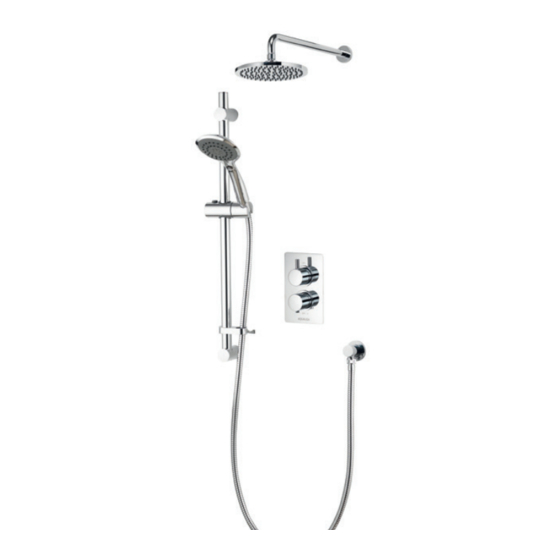
 operating parameters. (page 3). Refer to Cleaning the Thermostatic Cartridge section (page 27).
  • Page 32 Please note that calls may be recorded for training and quality purposes. The company reserves the right to alter, change or modify the product specifications without prior warning. ™ Trademark of Aqualisa Products Limited. Part No: 705367 Issue 02 Nov 20...

This manual is also suitable for:

Aqrndcv2Aqsqdcv1Aqsqdcv2

Table of Contents