Advertisement
Quick Links
Advertisement

Related Manuals for Aqualisa Dream DCV Series


Summary of Contents for Aqualisa Dream DCV Series
- Page 1 Dream Thermostatic Dual control mixer valve range Installation guide...
- Page 2 Index Introduction - Safety information - Product specification Connection to supplies - Pipe sizing - Flushing - Filters - Isolating valves - Pressures Boosted gravity system - Pump installation - Stored water capacities Combination boiler systems Balanced high pressure systems Typical water systems System components Valve installation instructions...
-
Page 3: Safety Information
Please refer to the product specification section below. If at any stage during installation you have any questions, please contact the Aqualisa customer helpline on 01959 560010 for assistance. Safety information This product must be installed by a competent person in accordance with all relevant current Water Supply Regulations. -
Page 4: Pipe Sizing
As this condition is not covered by our standard warranty terms, it is suggested that the filters be removed and checked by a competent person. In the event of any difficulties please contact the Aqualisa customer helpline for assistance. Isolating valves Suitable full way isolation valves must be fitted to both supplies in accordance with current Water Supply Regulations and our terms of warranty. -
Page 5: Pump Installation
A setting of 3bar is recommended. It should be noted that daytime pressures approaching 5bar can rise above the stated maximum overnight. A suitable PRV is available from Aqualisa. Dream DCV products are not suitable for mixed supply systems, e.g. -
Page 6: Stored Water Capacities
Stored water capacities The minimum capacity of the cold storage cistern should be not less than 225 litres (50 gallons). The capacity of the hot cylinder must be capable of meeting the anticipated demand. Combination boiler/multipoint system Dream DCV products are suitable for use with combination boiler systems. The combination boiler MUST have a minimum rating of 24kW (80,000 Btu) and be of the type fitted with a fully modulating gas valve. - Page 7 Typical system diagrams Typical pumped system installation Typical combination boiler system installation...
- Page 8 Typical system diagrams continued Typical UHW system installation Typical thermal storage unit system installation...
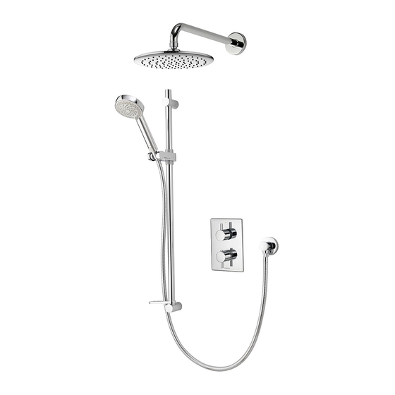
- Page 9 Components - Dream DCV with adjustable head Components - Dream DCV with wall drencher head...
- Page 10 Components - Dream DCV Divert with adjustable and wall drencher heads Components - Dream DCV Divert with adjustable head and bath overflow filler...
- Page 11 Dream DCV valve installation In addition to the guide below it is essential that the Important information section is read and understood and that you have all the necessary components (shown on page 9 or 10) before commencing installation. Failure to install the product in accordance with these instructions may adversely affect the warranty terms and conditions.
- Page 12 Secure the valve to the wall using suitable fixing screws. Secure the pipe work to the valve inlets using a suitable tool. Pipework connections are not supplied, suitable ¾ inch BSP unions/connection fittings are required. The valve can now be checked for leaks by rotating the flow control knob, ensuring the flow can discharge safely to waste.
- Page 13 Place the top on/off flow control knob into position and tighten the grub screw using the hexagonal key provided. The on/off flow control / Divert knobs can be fitted with or without the levers. If not using the levers, the hexagonal fixing points can be concealed using the blanking caps provided. N.B. We recommend these are placed on the underside of the control knobs.
- Page 14 If the lever is not to be fitted, place the temperature control screw cover into position and carefully push into place. If fitting the lever, secure the lever grub screw to the temperature control knob using the hexagonal key provided. Secure the temperature lever to the control knob.
- Page 15 Adjustable height head installation Adjustable height head installation Prepare pipework from the shower valve to the required position for the hose outlet using a Ø15mm copper pipe. Slide the wall spacer down the projecting pipe flush with the finished wall surface. Slide the 15mm gripper ring down the projecting pipe flush with the wall spacer fitting.
- Page 16 Ensuring the O-ring is in the correct position on the recess of the spigot section on the mounting plate, place the wall outlet onto the mounting plate in the 5 o’clock position and rotate clockwise until a stop is reached. Refit the locking screw taking care not to over tighten Drill and prepare two fixing points between 520mm (minimum) and 830mm (maximum) apart using the fixings provided, if suitable.
- Page 17 Slide the rail assembly up through the top rail end body. Align the small hole in the rail with the bottom rail end fixing point. Secure the rail assembly to the wall, using the fixings provided, if suitable, taking care to not over tighten. Place the rail end caps into the rail ends and push firmly into position.
- Page 18 Wall mount drencher head installation Prepare pipework from the shower valve to the required position for the fixed shower head using Ø15mm copper pipe. Cut the outlet pipe to a finished length (55mm – 150mm measured from the finished wall surface) using a rotary type cutter.
- Page 19 Run the shower for a few seconds to clear any debris that may be present. Slide the cover plate into position flush with the finished wall surface. Ensuring the rubber washer is in the correct position, attach the shower head to the fixed arm and carefully secure using a suitable spanner, or a tool with smooth jaws, sufficiently to lock the head into position.
- Page 20 Ensuring the rubber washer is correctly aligned, pass the bath waste clicker through the bath and secure to the waste body assembly Connect the bath waste to a suitable waste pipe. Offer the outlet body assembly into position at the rear of the bath ensuring the rubber washer is correctly aligned between the outlet body assembly and bath wall.
- Page 21 Waste pipe extension kit If required, for larger baths, a 900mm waste pipe conversion kit is available from Aqualisa Customer Service department. Please contact our Customer Service Department on 01959 560010. Unscrew the clamping nut and remove the waste pipe from the waste assembly.
- Page 22 Cleaning and maintenance Your Aqualisa shower system should be cleaned using only a soft cloth and washing up liquid. DO NOT USE ABRASIVE CLEANERS. To reduce the need for chemical descaling in hard water areas, your shower head incorporates a ‘clear flow’...
- Page 23 Dream DCV valve commissioning The Dream DCV thermostatic valves are factory set to a safe maximum temperature of 46°C, If required, the maximum outlet temperature can be adjusted following the procedure below: 1. Set the temperature lever to the mid blend (temperature stop button at 12 o’clock) position.
- Page 24 Dream DCV cartridge replacement ! Isolate both hot and cold water supplies. 1. Remove the grub screw cover located at the 6 o’clock position. !If the lever is fitted onto the bottom of the knob, unscrew the lever and remove the securing grub screw using the hexagonal key provided. 2.
- Page 25 To ensure the temperature stop button activates at the 12 o’clock position, ensure that when the white plastic stop ring is fitted onto the brass spindle, that the red marking on ring is at the 12 o’clock position. Turn the valve on and check the maximum temperature using a digital thermometer. If any adjustment is required, repeat steps 4 and 5 above until the desired maximum temperature has been reached.
-
Page 26: Troubleshooting Guide
Trouble shooting guide Symptom Possible cause Action Check that the supplies correspond Water output is either all hot Reversed inlet supplies with the inlet markings. Contact or all cold, or cold only Customer Services for a reverse inlet cartridge The cylinder temperature The temperature of the hot Water output is not hot should be at least 15˚c... - Page 27 Notes...
- Page 28 Part No:701142 Issue 01 Jun 14 Please note that calls may be recorded for training and quality purposes The company reserves the right to alter, change or modify the product specifications without prior warning TM Trademark of Aqualisa Products Limited...
- Page 29 Digital Showers Mixer Showers Power Showers Smart Showers Shower Towers From Top Shower Brands Mira Showers Aqualisa Showers Triton Showers Gainsborough Showers Shower Pumps can upgrade your showering experience even more Stuart Turner Shower Pumps Salamander Shower Pumps Grundfos Shower Pumps...
Need help?
Do you have a question about the Dream DCV Series and is the answer not in the manual?
Questions and answers