Table of Contents
Advertisement
Advertisement
Table of Contents

Related Manuals for Aqualisa Siren SL


Summary of Contents for Aqualisa Siren SL
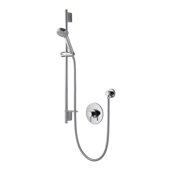
- Page 1 Siren Thermostatic mixer shower with 90mm Harmony head Installation guide...
-
Page 3: Table Of Contents
Index Introduction - Safety information - Product specification Connection to supplies - Pipe sizing - Flushing - Filters - Isolating valves - Pressures Gravity system - Siting - Pump installation - Stored water capacities Combination boiler systems Balanced high pressure systems Typical water systems System components p.10... -
Page 4: Introduction
Siren thermostatic valves provide close temperature stability and fail safe protection on appropriate high and low pressure systems. Please refer to the product specification section below. If at any stage during installation you have any questions, please contact the Aqualisa customer helpline on 01959 560010 for assistance. -
Page 5: Pipe Sizing
Debris accumulation may result in reduced flow from the shower head and noisy operation. As this condition is not covered by our standard warranty terms, it is suggested that the filters be removed and checked by a competent person. In the event of any difficulties please contact the Aqualisa customer helpline for assistance. -
Page 6: Siting
CYLINDER TEMPERATURE IN EXCESS OF 65°C MAY RESULT IN POOR SHOWER PERFORMANCE To minimise pressure loss we recommend that the hot and cold supplies are run in 22mm as close as reasonably possible to the mixing valve before reducing to 15mm. Siting For optimum performance, with gravity fed systems the distance between the bottom of the storage cistern and the shower head should be not less than 1m (when using an adjustable height head). -
Page 7: Balanced High Pressure Systems
The following regulators should be fitted to suit the relevant rated appliance as listed below: YELLOW = 24kW (80,000Btu) GREEN = 28kW (100,000Btu) BLUE = 35+kW (120,000+Btu) Please refer to pages 12 and 15 for fitting the regulator instructions. Balanced high pressure system The cold water supply must be drawn from the same mains supply as that to the hot water system (down stream of the cylinder manufacturer’s pressure limiting valve, where supplied) and the hot supply from the nearest convenient draw off point. -
Page 8: Gravity System
Typical system diagrams Typical gravity system installation Typical pumped system installation... - Page 9 Typical system diagrams continued Typical combination boiler system installation Typical UHW system installation Typical thermal storage unit system installation...
- Page 10 Components - Siren concealed with adjustable 90mm Harmony head Components - Siren exposed with adjustable 90mm Harmony head...
-
Page 11: Siren Exposed Valve
Siren exposed valve installation In addition to the guide below it is essential that the written instructions overleaf are read and understood and that you have all the necessary components (shown on page 10) before commencing installation. Failure to install the product in accordance with these instructions may adversely affect the warranty terms and conditions. -
Page 12: System Components
Prepare suitable 15mm pipe work in the desired location. If using existing 15mm pipe work, adjust the elbow centres accordingly. Offer the mounting plate onto the finished wall centred between the existing exposed pipe. Mark and prepare the fixing points using the fixings provided, if suitable. Secure the mounting plate to the finished wall using the screws provided, if suitable. - Page 13 Place the brass fitting into the elbow and tighten using a suitable hexagonal key to secure the flow regulator assembly into position. Refit the elbow to the valve assembly. Place the grub screws into position in the valve body. Offer the valve onto the mounting plate ensuring the elbows correctly align with the relevant pipework.
-
Page 14: Siren Concealed Valve
Secure the grub screw to the valve control knob using the hexagonal key provided. Secure the control lever to the control knob. If fitting this product for use with a high pressure system, the outlet flow regulator provided MUST be fitted. Place the flow regulator into the housing to create an assembly. - Page 15 Remove the black protective cover / mortar guard from the valve assembly and set aside. Place the mounting plate into position on the valve body ensuring the flat face aligns with the rear of the valve and secure using the bolts and hexagonal key provided.
- Page 16 Prepare suitable 15mm inlet pipe work and construct a suitable 15mm outlet supply pipe to the desired location for the wall outlet or fixed head. Place the vale into the required position within the wall and mark and prepare the fixing points using the fixings provided, if suitable.
-
Page 17: Adjustable Height Harmony Head
Secure the grub screw to the valve control knob using the hexagonal key provided. Secure the control lever to the control knob. Please refer to pages 17 to 20 for shower kit installation instructions. Adjustable height Harmony head installation Adjustable height head installation The adjustable height heads are suitable to be fitted with either concealed or exposed shower valves. - Page 18 Remove the locking screw, rotate the chrome outlet assembly and remove the outlet from the wall mounting plate. Place the wall outlet mounting plate onto the pipe assembly and mark and prepare the fixing points, using the fixings provided, if suitable. Secure the wall mounting plate to the wall using the screws provided, if suitable.
- Page 19 Ensuring the lever is in the upright position, pass the rail through the handset holder. Carefully slide the gel hook onto the rail under the handset holder. Current water supply regulations state that the handset should not be allowed to pass a point 25mm above the spill over level of the bath or shower tray.
- Page 20 Exposed valve If required, place the flow regulator into the recess in the flow regulator housing. Place the flow regulator assembly into position inside the valve outlet ensuring the flow regulator o’ring faces the incoming flow. Ensuring the hose washer is in position secure the hose to the valve or wall outlet hand tight only.
-
Page 21: User Guide - Shower Valves
Cleaning and maintenance Your Aqualisa shower system should be cleaned using only a soft cloth and washing up liquid. DO NOT USE ABRASIVE CLEANERS. To reduce the requirement for chemical descaling in hard water areas, the shower heads incorporate soft rub clean teats. -
Page 22: Commissioning
Siren valve commissioning The Siren thermostatic valves are factory set to a safe maximum temperature of 48°C. If required, the maximum outlet temperature can be adjusted by following the procedure below: Remove the control lever and grub screw using the hexagonal key provided and set aside. Insert the hexagonal key into the control knob and loosen the grub screw. -
Page 23: Trouble Shooting Guide
Trouble shooting guide Symptom Possible cause Action Check that the supplies Water output is either all hot Reversed inlet supplies correspond with the inlet or all cold, or cold only markings The cylinder temperature The temperature of the hot Water output is not hot should be at least 15˚c enough water cylinder is too low... - Page 24 Part No.659701 Issue 01 Jan 11 Please note that calls may be recorded for training and quality purposes The company reserves the right to alter, change or modify the product specifications without prior warning ® Registered Trademark Aqualisa Products Limited...
- Page 25 Pdf Supplied By http://www.plumbworld.co.uk/...
Need help?
Do you have a question about the Siren SL and is the answer not in the manual?
Questions and answers