
Related Manuals for Kinco FD5 Series


Summary of Contents for Kinco FD5 Series
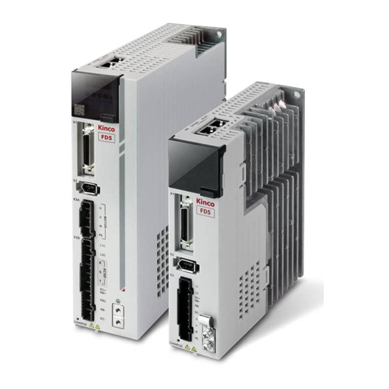
- Page 1 Manual Kinco FD5 series AC servo system Kinco Electric (shenzhen) Ltd. www.kinco.cn...
- Page 2 Thank you for using Kinco FD5 series of servo products. FD5 series AC servo is an economical product launched by Kinco for the general servo market, with a power range between 200W to 3KW. The new generation servo products support CANopen, EtherCat, Modbus, Profinet and other communication protocols.
- Page 3 Identifications Description Danger Wrong operation could lead death or serious injury. Warning Risk of minor injury or serious property damage. Other Identifications Attention May cause equipment damaged or function disable Remind Suggestion, reminding, or references Manual Edition Record Edition Chapter Date Edition Detail All Chapter...
-
Page 4: Table Of Contents
Preface and Product Confirmation ..........................- 3 - Confirmation ..................................- 3 - Chapter 1 Servo system model and configuration description ..................5 1.1 Description of product model ............................5 1.2 Drive nameplate description .............................. 5 1.1Motor model description ..............................6 1.2 Motor nameplate description ............................ - Page 5 Panel operation ..............................43 Panel menu structure and navigation ......................44 Easy Use Function ..............................45 4.3.1 Setup process with Easy Use Function ........................45 4.3.2 Flowchart and description of the EASY menu ...................... 47 4.3.3 Flowchart and description of the tunE menu ....................... 51 4.3.4 Reasons for the failure of tunning..........................
- Page 6 Torque mode(4) ..............................85 Position mode(1) ..............................86 6.4.1 DIN introduction to Location Position ........................87 6.4.2 Position flow mode ................................ 89 Pulse mode (-4) ..............................94 6.5.1 Pulse mode setting steps............................. 95 6.5.2 Other function ................................. 97 6.5.3 Electronic gear ratio switching (expert mode) ..................... 98 6.5.4 Master-slave mode ................................
- Page 7 9.5 F005 ....................................152 Chapter 10 Communication ..............................154 10.1 RS232 wiring ................................154 10.1.1 RS232 Hardware port ............................154 10.1.2 RS232 communication cable ......................... 154 10.1.3 RS232 Transfer protocol ..........................154 10.1.4 RS232 Data protocol ............................155 10.2 RS485 Communication............................160 10.2.1 RS485 Hardware wiring...........................
-
Page 8: Chapter 1 Servo System Model And Configuration Description
Chapter 1 Servo system model and Kinco FD5 AC series servo driver manual configuration description Chapter 1 Servo system model and configuration description 1.1 Description of product model FD 4 2 5 – EA - 000 FD Series Software version number Input AC220V RS232、EtherCAT... -
Page 9: Motor Model Description
Chapter 1 Servo system model and Kinco FD5 AC series servo driver manual configuration description 1.1 Motor model description SMC 60 S – 0040 – 30 Y A K – 5 L S U Communication encoder socket YD series general aviation socket... -
Page 10: Servo Drive Specifications
Chapter 1 Servo system model and Kinco FD5 AC series servo driver manual configuration description 1.3 Servo drive specifications Models FD425-□A- FD425-□F- FD435-□A- FD625-□A- 1PH,200-240VAC±10% 1PH,3PH, 3PH, 380- Power Power supply 50/60Hz±3HZ (750W 7A) 200- 415VAC±10% supply (200W 3A) 240VAC±... - Page 11 Chapter 1 Servo system model and Kinco FD5 AC series servo driver manual configuration description External pulse input control Order control 8-segment position can be controlled using DIN signal method Internal paramater of communication setting control Position control Mode Order Low-pass filter(Set by internal prameter),S-curve...
- Page 12 Chapter 1 Servo system model and Kinco FD5 AC series servo driver manual configuration description frequency 7 digital inputs,with COM1 terminal for PNP(high level valid 12.5- Input 30V) or NPN(Low level valid 0~5V)conncetion specification Digital Define freely according to requirement, supporting following...
-
Page 13: Configuration Table
Chapter 1 Servo system model and Kinco FD5 AC series servo driver manual configuration description 1.5 Configuration table Servo driver Rated Power cable Series Servo motor Description Encoder cable power/ Pulse Pulse Profinet EtherCAT Brake cable Rated CANopen MODBUS 485... -
Page 14: Chapter 2 Servo System Installation Requirements And Notes
Chapter 2 Servo system installation Kinco FD5 AC series servo driver requirements and notes manual Chapter 2 Servo system installation requirements and notes 2.1 Installation of drive 2.1.1 Installation requirement Figuire2-1 FD425-□A Product installation drawing... - Page 15 Chapter 2 Servo system installation Kinco FD5 AC series servo driver requirements and notes manual Figuire 2-2 FD425-□F(1000W) Product installation drawing Figuire 2-3 FD435-□A Product installation drawing...
-
Page 16: Installation Distance And Direction
Chapter 2 Servo system installation Kinco FD5 AC series servo driver requirements and notes manual Figure 2-4 FD625-□A Product installation drawing 2.1.2 Installation distance and direction Please install the servo drive vertically and drill holes according to the Hole Position for Fixation,... - Page 17 Chapter 2 Servo system installation Kinco FD5 AC series servo driver requirements and notes manual Air outlet Air outlet 20mm 20mm 20mm 20mm 20mm Air intake Air intake Figure 2-5 FD425 Installation direction and requriement Air outlet Air outlet 20mm...
-
Page 18: Drive Usage Requirements
Chapter 2 Servo system installation Kinco FD5 AC series servo driver requirements and notes manual Danger! Please make sure that the drive is installed securely and the screws are ⚫ tightened to prevent the drive from falling and hurting people during use. - Page 19 Chapter 2 Servo system installation Kinco FD5 AC series servo driver requirements and notes manual —Corrosive gases Please use the original packaging for storage and transportation, the original packaging provides ⚫ sufficient protection to avoid common problems. Environmental conditions Table 2-1 Environmental requirements...
-
Page 20: Servo Motor Installation
Chapter 2 Servo system installation Kinco FD5 AC series servo driver requirements and notes manual Technical requirements In order to use the product correctly and safely, the following requirements should be always observed: Operation of the product in accordance with the relevant safety regulations is permitted only if the ⚫... -
Page 21: Environment Conditions
Chapter 2 Servo system installation Kinco FD5 AC series servo driver requirements and notes manual 2.3.2 Environment conditions Table 2-2 Environment conditions Environment Conditions Working -20℃~40℃(no ice) Temperature Working Under 90%RH (no condensation) humidity Storage -20℃~70℃(no ice) temperature Storage 5~95%RH(no condensation)... -
Page 22: Precautions
Chapter 2 Servo system installation Kinco FD5 AC series servo driver requirements and notes manual 2.3.3 Precautions... - Page 23 Chapter 2 Servo system installation Kinco FD5 AC series servo driver requirements and notes manual Table 2-3 Precautions Item Description Anti-rust Please wipe anti-rust agent on the motor's shaft and then make some anti-rust treatments. Improper installation method will cause damage of motor's encoder. Please note the following during the installation process: ◆...
- Page 24 Chapter 2 Servo system installation Kinco FD5 AC series servo driver requirements and notes manual Please do not make cable bending or pull the cable. When using it, please do Cable not make it too tight. In terms of connectors, please note the following: When connectors are connected.
-
Page 25: Chapter 3 Installation And Wiring
Kinco FD5 AC series servo driver Chapter3 Installation and wiring Chapter 3 Installation and wiring 3.1 Drive description Digital Screen RS232 X1:I/O terminal X2:Encoder terminal X3:Power terminal X4:Bus terminal Main power supply DC+/RB+ Dcbus input/ SW1: 120R Extrenal braking resistor... -
Page 26: External System Connection
Kinco FD5 AC series servo driver Chapter3 Installation and wiring 3.2 External system connection Figure 3-3 FD425 external connection Figure 3-4 FD435 external connection... - Page 27 Kinco FD5 AC series servo driver Chapter3 Installation and wiring Figure 3-5 FD625 external connection Table 3-1 External system connect introduce Electric Function equipment Molded case In the event of overcurrent, short circuit, or undervoltage, the circuit breaker circuit automatically shuts off the power supply, thus protecting the circuit and drive breakers equipment from damage.
- Page 28 Kinco FD5 AC series servo driver Chapter3 Installation and wiring Table 3-2 Recommended breaker model Servo drive models Recommended breaker Models Specifications Manufacturer FD425-□A NXBLE-32-2P-C6 230V~(1P+N、2P),6A CHNT FD425-□F(1000W) NXBLE-32-2P-C10 230V~(1P+N、2P),10A FD435-□A NXBLE-32-2P-C20 230V~(1P+N、2P),20A FD625-□A NXBLE-32-4P-C16 400V~(3P、3P+N、4P),16A Table 3-3 Recommended noise filter...
-
Page 29: Wiring Connection Mode
Kinco FD5 AC series servo driver Chapter3 Installation and wiring Danger! FD435/ FD625 drives are factory-configured with short wires connected to ⚫ DC+/RB- and RB2, indicating the use of internal braking resistors (FD435 built-in 100Ω/20W;FD625 built-in 300Ω/20W),When the braking power exceeds the tolerable range of the internal braking resistor, the drive will alarm the braking resistor to be abnormal and display "0100". -
Page 30: Drive Anti-Interference Measurements
Kinco FD5 AC series servo driver Chapter3 Installation and wiring In order to ensure the stable and safe use of the product, the following matters should be paid attention to when wiring the drive: Pay attention to the fixation of the cable during the assembly process, and do not apply stress ◆... - Page 31 Kinco FD5 AC series servo driver Chapter3 Installation and wiring ⚫ When using multiple servo drives, do not connect the ground wires of multiple drives in series, and use a single-point grounding method; ⚫ The drive should be grounded with the shortest and thickest possible cable (>2mm²). If the ground wire is long, the diameter of the ground wire should be increased (≥4mm²) to ensure...
-
Page 32: Dc Bus
Kinco FD5 AC series servo driver Chapter3 Installation and wiring Main Power Noise filter supply Driver Encoder cable Driver Encoder cable L2 U Shielding layer Shielding layer Grounding resistance<100Ω Figure 3-7 Grounding measurement of multiple drives ⚫ In order to suppress interference as much as possible, twisted pair cables with shielded nets can be used for power lines, encoder lines, and IO control lines, but the shielding layer must be properly grounded;... -
Page 33: Rs232 Serial Port
PC side serial port PC side pin difiniation Header pin definition name pin number pin number Receive data (RXD) Send data (TXD) Signal ground(GN Users can purchase the FD5 drive Mini-usb 5p to DB9 female RS232 cable (Kinco order number: PDC -... -
Page 34: External Input And Output Connection(X1
USB-1(5)) If your computer does not have an RS232 serial port, you will also need to use a USB to DB9 serial cable to connect. Figure 3-11 FD5 Drive 232 debug cable ⚫ Purchase link of Kinco official Tmall store: https://detail.tmall.com/item.htm?spm=a212k0.12153887.0.0.4d7c687 deB8shy&id=652422874770&skuId=4707119953745 3.4 External input and output connection(X1)... - Page 35 Kinco FD5 AC series servo driver Chapter3 Installation and wiring Enable DIN1 Reset errors DIN2 Ready OUT1+ Start homing DIN3 OUT1- P limit+ DIN4 Motor brake OUT2+ Digital input P limit- DIN5 OUT2- Digital DIN6 Pos reached output OUT3 Home signal...
- Page 36 Kinco FD5 AC series servo driver Chapter3 Installation and wiring Attention Figure 3-8 shows the X1 wiring of the default IO function of the FD5-LA/CA ⚫ drive, and Figure 3-10 shows the X1 wiring of the default IO function of the FD5-PA drive.
- Page 37 Kinco FD5 AC series servo driver Chapter3 Installation and wiring Table 3-8 Pin definition of external IO terminals Pin number Signal ID Signal name Specifications OUT1+ Differential output Open collector output OUT1- MAX voltage DC30V OUT2+ MAX current 100mA OUT2-...
-
Page 38: Digital Signal Input
Kinco FD5 AC series servo driver Chapter3 Installation and wiring Output 5V A, B, Z differential signals, the frequency division output range is ENCO_Z 0~65536; for multi-axis ENCO_/Z synchronization, the maximum output ENCO_B Encoder signal output frequency is 5MHz ENCO_/B... - Page 39 Kinco FD5 AC series servo driver Chapter3 Installation and wiring Digital input wiring example① Driver Relay When the host computer is relay Power input Relay Power Relay Power Relay Power Relay Power Digital output wiring example② When the host 24V+...
-
Page 40: Pulse Command Input
Kinco FD5 AC series servo driver Chapter3 Installation and wiring 3.4.3 Pulse command input Table 3-11 Pulse input wiring example Pulse input is divided into ordinary pulse input channel and high- Instruction speed pulse input channel High-speed pulse input channel supports RS422 differential signal, voltage range DC3.3-5V, MAX pulse frequency 4MHz... -
Page 41: Brake Connection
Kinco FD5 AC series servo driver Chapter3 Installation and wiring High-speed pulse input wiring example① Driver PNP wiring method 3.4.4 Brake connection Table 3-12 Brake connection example Instruction By default, OUT2 of the drive is the brake control port. An external relay is required to control the motor brake. - Page 42 Kinco FD5 AC series servo driver Chapter3 Installation and wiring Attention The use of the holding brake can ensure that the motor shaft can remain stationary in the state of de-enable or power-off. Please make sure that the holding brake has been opened before the motor runs.
-
Page 43: Encoder Input(X2
Kinco FD5 AC series servo driver Chapter3 Installation and wiring 3.5 Encoder input(X2) Table 3-14 Magnetic encoder (MAK) pin definition Pin number Pin name Pin function 5V power output positive terminal 5V power output negative terminal CLOCK+ Clock signal CLOCK-... -
Page 44: Power Port(X3
Kinco FD5 AC series servo driver Chapter3 Installation and wiring 3.6 Power port(X3) Table 3-16 FD425 Power port instruction Port Pin name Pin function Drive mains power input Unidirectional line voltage 200~ 240VAC ±10% 50~60Hz ±3Hz, (750W 7A),(200W DC bus input positive terminal... - Page 45 Kinco FD5 系列伺服驱动器使用手册 第四章 数字面板操作 Product model RS485 Plug pin Drive side pin name Drive side pin Connecting signal definition number to the host computer 485+ TX+/A FD425-LA-000 FD435-LA-000 FD625-LA-000 485- TX-/B Table 3-18 RS485 Communication port pin definition Table 3-19 CAN Communication port pin definition...
-
Page 46: Chapter 4 Controller Setup With Led Panel
Kinco FD5 系列伺服驱动器使用手册 第四章 数字面板操作 Chapter 4 Controller setup with LED panel 4.1 Panel operation After the servo system is installed and wired correctly according to the specifications and precautions, the servo drive can be set for specific application scenarios. -
Page 47: Panel Menu Structure And Navigation
Kinco FD5 系列伺服驱动器使用手册 第四章 数字面板操作 Positive limit signal active P..L Negative limit signal active n..L Positive and negative limit signal active Pn.L The drive is not configured with the motor model FFF.F Blinking Error Attention 1. The setting value is out of the setting range of the parameter. -
Page 48: Easy Use Function
Kinco FD5 系列伺服驱动器使用手册 第四章 数字面板操作 4.3 Easy Use Function The Easy Use function helps users set up the CD3 motor controller for the main types of applications in a very short time. The LED panel guides the user step by step through the settings of the few most important parameters in order to prepare the controller for the desired application. - Page 49 Kinco FD5 系列伺服驱动器使用手册 第四章 数字面板操作 START Execute the flow chart of EASY Good Jog the machine, evaluate the performance Not good Measure the Inertia Ratio by Tn03 Adjust the Stiffness by Tn01 Can not figure out by Not Good adjusting the stiffness...
-
Page 50: Flowchart And Description Of The Easy Menu
Kinco FD5 系列伺服驱动器使用手册 第四章 数字面板操作 4.3.2 Flowchart and description of the EASY menu Figure 4-3 EASY Flowchart of the EASY menu Attention The menu is exited automatically if there is no operation in 30s, and users have to start again. Entered data is valid immediately but must be saved via EA00. - Page 51 Kinco FD5 系列伺服驱动器使用手册 第四章 数字面板操作 Table 4-2 Easy menu parameters Parameter Description Default For a new factory drive, the motor model is 00, and the digital panel displays 3030. If the drive is connected to the correct motor, the motor Motor type model will be automatically recognized and saved by the drive.
- Page 52 Kinco FD5 系列伺服驱动器使用手册 第四章 数字面板操作 Write “1” to save control and motor parameters. Write “2” to save control and motor parameters and reboot the servo. Save parameters Write “3” to reboot the servo. EA00 Write “10” to initialize the control parameters.
- Page 53 Kinco FD5 系列伺服驱动器使用手册 第四章 数字面板操作 Pulse train mode configuration, command types 0, 1 or 2 in EA02: Enable Ready DIN1 OUT1+ Reset Errors DIN2 OUT1- Start Homing Motor Brake DIN3 OUT2+ P limit+ DIN4 OUT2- Digital Digital Pos Reached Input...
-
Page 54: Flowchart And Description Of The Tune Menu
Kinco FD5 系列伺服驱动器使用手册 第四章 数字面板操作 4.3.3 Flowchart and description of the tunE menu The tunE panel menu includes parameters and functions for auto-tuning with inertia measurement and servo control loop adjustment via just one parameter, namely stiffness. After processing the EASY menu, the controller defaults the stiffness value and the inertia_ratio based on reasonably estimated values according to, load type and application settings in EA06. - Page 55 Kinco FD5 系列伺服驱动器使用手册 第四章 数字面板操作 Table 4-4 tunE parameters Description Parameter Defult level of control stiffness from 0 to31 determines the bandwidth Belt: (BW) of the velocity loop and the position loop (see table 4-5). Stiffness tn01 The larger the value, the greater the stiffness. If this parameter is...
- Page 56 Kinco FD5 系列伺服驱动器使用手册 第四章 数字面板操作 must be confirmed by SET Inertia measuring distance (unit: 0.01 rev), for example 22 Safe_Dist tn04 represents 0.22 motor revolutions. The maximum is 0.4 revolutions Write “1” to save control and motor parameters. Write “2” to save control and motor parameters and reboot Saving the servo.
-
Page 57: Reasons For The Failure Of Tunning
Kinco FD5 系列伺服驱动器使用手册 第四章 数字面板操作 -2: Indicates that the calculated inertia coefficient is too large or too small, and the measurement result is not within the normal range. The integral needs to be adjusted, the limit parameters need to be re-tuned, and the result is invalid. -
Page 58: Tuning Case
Kinco FD5 系列伺服驱动器使用手册 第四章 数字面板操作 Too much friction or external force is applied to the axis to be tuned Too big backlash in the mechanical path between the motor and the load Inertia ratio is too large The mechanical path contains too soft components (very soft belts or couplings) 4.3.5 Tuning case... - Page 59 Kinco FD5 系列伺服驱动器使用手册 第四章 数字面板操作 Operation instructions for flexible connection setting cases 1、Enter EA01 through the panel keys, and confirm that the motor model is correct. 2、Enter EA06 to set the tuning command type to 1001, which means that the axis operation...
-
Page 60: Jog Mode(Test Run
Kinco FD5 系列伺服驱动器使用手册 第四章 数字面板操作 4.4 Jog mode(Test run) The Jog mode is intended to be used for a motor test run by the buttons of the LED panel without the need for any other command signal. No matter other Operation_Mode and velocity settings, in the Jog mode the controller controls the motor rotating with the velocity set by Jog_RPM(d3.52) in instantaneous velocity... - Page 61 Kinco FD5 系列伺服驱动器使用手册 第四章 数字面板操作 Table 4-6:F007 example F007 LED display Meaning The latest error is Extended Error. Press “SE T” k ey to see the 000.1 Error State 2(2602.00 ) value 02.00 The earliest error is following Error 0100 There was Chop Resistor error, it’s neither the earliest nor the latest...
-
Page 62: Chapter5 Kincoservo +, User Guide
Kinco FD5 系列伺服驱动器使用手册 第五章 KincoServo 上位机使用指南 Chapter5 KincoServo +, user guide Thes chapter contains information about how to use the PC software Kincoservo+ Figure 5-1 Main window of Kincoservo+ 5.1 Getting started 5.1.1 Language Language can be switched between English and Chinese via menu item Tools->Language. -
Page 63: Starting Communication
Kinco FD5 系列伺服驱动器使用手册 第五章 KincoServo 上位机使用指南 5.1.3 Starting communication Click menu item Communication->Communication settings. The following window appears: Figure 5-2 Communication setting Select the right COM port (if it’s not shown click the “Refresh” button), baud rate and COM ID (Node ID), and then click the "OPEN”... -
Page 64: Init Save Reboot
Kinco FD5 系列伺服驱动器使用手册 第五章 KincoServo 上位机使用指南 Click Add and double click the required object from the Object Dictionary. The selected object is then added to the list. Click Delete. The selected object is removed from the list. Click Help to read a description of the selected object in the Object Dictionary. -
Page 65: Read/Write Controller Configuration
Kinco FD5 系列伺服驱动器使用手册 第五章 KincoServo 上位机使用指南 Figure 5-5 Software version Attention Do not switch off the power or disconnect the RS232 cable during firmware loading. If the download process is interrupted, first reset controller power. Then select the firmware file and click the Download button, and finally start RS232 communication. -
Page 66: Write Setting To Controller
Kinco FD5 系列伺服驱动器使用手册 第五章 KincoServo 上位机使用指南 Attention The .cdo file defines which objects will be read out, but if the object doesn’t ⚫ exist in the controller, the result will be “False”(displayed in red). 5.4.2 Write setting to controller Click Tools->R/W Controller Configuration->Write Settings to Controller or click the button. -
Page 67: Digital Io Function
Kinco FD5 系列伺服驱动器使用手册 第五章 KincoServo 上位机使用指南 5.5 Digital IO function Click menu item Controller->Digital IO Functions or click the button . The following window appears. Function and polarity are shown. Shown as default function and polarity. Figure 5-8 Digital IO 5.5.1 Digital... - Page 68 Kinco FD5 系列伺服驱动器使用手册 第五章 KincoServo 上位机使用指南 Figure 5-9 Digital input Function:Click to select Din function setting click delete the DIN function Real:Shows the real digital input hardware status. means “active”, logic status of the digital input is 1. means “inactive”, logic status of the digital input is Simulate: Simulates the digital input active hardware signal.
- Page 69 Kinco FD5 系列伺服驱动器使用手册 第五章 KincoServo 上位机使用指南 1: Velocity control loop integrating gain off Kvi off 0: Velocity control loop integrating gain has been set. Refer to chapter 7 for more information about Kvi P limit+ Positive/Negative position limit switch input for “normally closed” limit switches...
-
Page 70: Digital Outputs
Kinco FD5 系列伺服驱动器使用手册 第五章 KincoServo 上位机使用指南 Attention DIN control word selection (2020.0F) is set to 0x2F by default. For the definition of control word, please refer to Chapter 6.1 5.5.2 Digital outputs Figure 5-10 Digital output Function:Click to select Din function setting click delete the DIN function Real:Shows the real digital input hardware status. -
Page 71: Fast Capture
Kinco FD5 系列伺服驱动器使用手册 第五章 KincoServo 上位机使用指南 Error Controller error Under position mode, position difference between Pos_Actual and Pos reached Pos_Target<Target_Pos_Window(6067.00),duration>=Position_Window_time(60 68.00) |Speed_1ms(60F9.1A)|<=Zero_Speed_Window(2010.18) and Zero speed duration >=Zero_Speed_Time(60F9.14) Signal for controlling the motor brake. By this signal an external relay can be controlled, by which the motor brake is controlled. - Page 72 Kinco FD5 系列伺服驱动器使用手册 第五章 KincoServo 上位机使用指南 Falling_Captured 1 2010.21 Uint8 Rising_Captured 2 2010.22 Uint8 Falling_Captured 2 2010.23 Uint8 Raising_Capture_Position 1 2010.24 Int32 Falling_Capture_Position 1 2010.25 Int32 Raising_Capture_Position 2 2010.26 Int32 Falling_Capture_Position 2 2010.27 Int32 When DIN function Fast_Capture1 is configured to DIN and a rising DIN edge occurs, Rising_Captured1 is changed to 1.
-
Page 73: Scope
Kinco FD5 系列伺服驱动器使用手册 第五章 KincoServo 上位机使用指南 5.6 Scope The scope function is for sampling the selected objects’ value with a flexible sample cycle (defined by Sample Time) and a flexible total sample number (defined by Samples) During operation, if performance does not meet the requirement or any other unexpected behaviour occurs, it’s highly advisable to use the scope function to do the analysis. - Page 74 Kinco FD5 系列伺服驱动器使用手册 第五章 KincoServo 上位机使用指南 sample value and the differences of X1, X2 and Y1, Y2 appear in the Moving Cursors:Hold down the left mouse button, drag the cursor to move, the sampled data, the difference between X1X2 and Y1Y2 will be displayed in the following area:...
-
Page 75: Error Display And Error History
Kinco FD5 系列伺服驱动器使用手册 第五章 KincoServo 上位机使用指南 bit 2:1—use mask(23000E20), AND gate Note: You can no longer use the up and down arrows on the oscilloscope page to set the trigger edge to prevent conflicts. Trigger source Oscilloscope Trigger Object 2300.12... - Page 76 Kinco FD5 系列伺服驱动器使用手册 第五章 KincoServo 上位机使用指南 table 5-8 Error_state(2601.00)information Error name Error code Description Extended Error Refer to object “Error_State 2”(2602.00) Encoder not No communication encoder connected 0x7331 connected Encoder internal Internal encoder error 0x7320 Encoder CRC Communication with encoder disturbed...
- Page 77 Kinco FD5 系列伺服驱动器使用手册 第五章 KincoServo 上位机使用指南 Reserved Reserved Reserved DIN "pre_enable" function is configured, but the DIN 0x5443 is inactive when the controller is enabled / going to External enable be enabled Positive position limit (after homing) – position limit...
- Page 78 Kinco FD5 系列伺服驱动器使用手册 第五章 KincoServo 上位机使用指南 ADC sampling Current sampling ADC reaches limit, current runaway 0x2321 saturation service timeout Communication Bus Error Extension 0x81FF Table 5-11 Error mask Interna Type Meaning (Bit meaning please see table5-7 and Name Defaul table 5-8) addre 2605.0...
-
Page 79: Chapter 6 Operation Modes And Control Modes
Kinco FD5 系列伺服驱动器使用手册 第六章 工作模式介绍 Chapter 6 Operation modes and control modes Controller parameters can be set via the control panel or the RS232 port with host computer software. In the following introduction, both the panel address (if it’s available) and the internal address will be shown in the object tables. - Page 80 Kinco FD5 系列伺服驱动器使用手册 第六章 工作模式介绍 Table 6-2 Digital function output Panel address Internal address Type Name Value (hex): description 0001: Ready Dout1_Function 0002: Error d3.11 2010.0F Uint16 0004: Pos Reached Dout2_Function d3.12 2010.10 Uint16 0008: Zero Speed Dout3_Function 0010: Motor Brake d3.13...
-
Page 81: Step 3: Set Necessary Parameters
Kinco FD5 系列伺服驱动器使用手册 第六章 工作模式介绍 T a b l e 6-4 Digital input and output signal polarity and simulation setting method ① ② ③ ④ 0:input and output ports are Channel input/output keep Polarity port normally closed input:1-7 setting 1:input and output ports are D3.08... - Page 82 Kinco FD5 系列伺服驱动器使用手册 第六章 工作模式介绍 Table 6-6 basic parameters Panel Internal Type Name Description address address -3 : Immediate speed mode Operation_mod D0.00 6060.00 3 : Speed mode with acceleration and deceleration 1: position mode...
- Page 83 Kinco FD5 系列伺服驱动器使用手册 第六章 工作模式介绍 -4: Pulse mode 4: Torque Mode 0x0F/0x2F: Used when operation_mode is -3, 3, -4, 4 and position flow mode 0x2F->0x3F: Activate the absolute position command, the absolute positioning command will not be executed immediately according to Controlword D0.01...
- Page 84 Kinco FD5 系列伺服驱动器使用手册 第六章 工作模式介绍 Since the absolute value encoder data is saved by the battery, when the device runs for the first time, it is necessary to clear the multi-turn data at the origin position. After clearing the encoder status and multi- turn data, restart/reset the drive.
-
Page 85: Step 4: Save And Reboot
Kinco FD5 系列伺服驱动器使用手册 第六章 工作模式介绍 Attention When the value directly written in the Operation_mode through the basic operation interface cannot be saved after power off and restart, the Operation_mode can be saved by configuring the Operation_mode control function on the input port of the drive, but it should be noted that the Operation_mode is selected 0 first. -
Page 86: Din Speed Mode
Kinco FD5 系列伺服驱动器使用手册 第六章 工作模式介绍 6.2.2 DIN Speed mode The Din_Speed object window in PC software can be accessed from menu item Controller->Control Modes->DIN Speed Mode Table 6-9 DIN Speed mode Panel Internal Type Name Description Value address address Din_Speed[0] D3.18... - Page 87 Kinco FD5 系列伺服驱动器使用手册 第六章 工作模式介绍 2. Analog-speed control (250207) is 0, close the analog-speed channel。...
-
Page 88: Torque Mode(4)
Kinco FD5 系列伺服驱动器使用手册 第六章 工作模式介绍 3. At least one of DIN speed index 0, DIN speed index 1 and DIN speed index 2 is defined in the digital input DIN as the switching signal of the speed segment. 6.3 Torque mode(4) In the torque mode, the CD3 motor controller causes the motor to rotate with a specified torque value. -
Page 89: Position Mode(1)
Kinco FD5 系列伺服驱动器使用手册 第六章 工作模式介绍 6.4 Position mode(1) In the position mode, the CD3 motor controller causes the motor to rotate to an absolute or relative position. The position / velocity command is specified via Target_Position / Profile_Speed or via position flow。... -
Page 90: Din Introduction To Location Position
Kinco FD5 系列伺服驱动器使用手册 第六章 工作模式介绍 Profile_ Profile acceleration for positioning 6083.00 User defined acceleration Profile_ Profile deceleration for positioning 6084.00 User defined deceleration 0x2F->0x3F: Activate the absolute position command. The absolute positioning command will not be 0x2F->0x3F executed immediately according to 0x4F->0x5F... - Page 91 Kinco FD5 系列伺服驱动器使用手册 第六章 工作模式介绍 2020.13 Din_pos[7] Select the position segment L to be set (L range Din_position_sel D3.40 2FF1.01 is 0-7, corresponding to the internal position ectL segment 0-7 in turn) D3.41 2FF1.02 Din_position_M Number of pulses set in position segment (L) =M*10000+N D3.42...
-
Page 92: Position Flow Mode
Kinco FD5 系列伺服驱动器使用手册 第六章 工作模式介绍 In the multi-segment position mode, the position-to-signal of the 1-7 segment of ⚫ the Din position is represented by the BCD code composed of the multi-function signal 0-2. The command activation can set the bit4 of the control word to activate the ⚫... - Page 93 Kinco FD5 系列伺服驱动器使用手册 第六章 工作模式介绍 T a b l e 6-16 Input port function of PosTable mode Name Description If Cond0 ON, Condition0 = PosTable Cond0 (refer to introduction concerning Cond0 ON) PosTable Cond0 If Cond1 ON, Condition1 = PosTable Cond1 (refer to introduction concerning Cond1 ON)
- Page 94 Kinco FD5 系列伺服驱动器使用手册 第六章 工作模式介绍 Figure 6-2 Position flow mode window The DIN Start PosTable signal (rising edge) triggers the entry index (specified via the DIN function) task, but whether or not the task is executed depends on the start condition (CTL reg bit14-15).
- Page 95 Kinco FD5 系列伺服驱动器使用手册 第六章 工作模式介绍 CTL Reg: Contains following bits: Bits 0-4: Next index, defines the index of the next position control task Bits 5-7: reserved Bit 8: Next / stop, 1: Next; go to next task if condition (see bit9-11) = 1 and loops checking is OK (see Loops) after current positioning task is finished.
- Page 96 Kinco FD5 系列伺服驱动器使用手册 第六章 工作模式介绍 For convenience, all CTL_Reg bits can be set in the following fields: Figure 6-4 CTL Reg edit Loops Defines loop limit for the task which is running in loops; ⚫ 0: no limit, ≥ 1: position flow stops when loop count = loops, or if the next index’s loop count = next index’s loops.
-
Page 97: Pulse Mode (-4)
Kinco FD5 系列伺服驱动器使用手册 第六章 工作模式介绍 6.5 Pulse mode (-4) In the pulse mode, the target velocity command is specified via the pulse input with gear ratio, Please refer to Figure 4-4 in Chapter 4.3.2 for the wiring method in pulse mode. It can be debugged by expanding the relevant parameters in the software. -
Page 98: Pulse Mode Setting Steps
Kinco FD5 系列伺服驱动器使用手册 第六章 工作模式介绍 Gear Pre-pulse The main encoder port counts before D1.21 2508.04 data inputting pulse electronic gear Gear Post-pulse The main encoder port counts after D1.22 2508.05 data inputting pulse electronic gear Gear Pre-pulse Pulse speed of spindle input(pulse/ms) D1.23... - Page 99 Kinco FD5 系列伺服驱动器使用手册 第六章 工作模式介绍 modified, it needs to be saved and restarted to take effect. Table 6-16 Pulse input supported by the drive Pulse mode Forward Reverse...
-
Page 100: Other Function
Kinco FD5 系列伺服驱动器使用手册 第六章 工作模式介绍 CW/CCW Step2:Confirm CPLD Pulse Filter Setting The CPLD filter inside the drive is used to filter the high-frequency clutter at the pulse input port to prevent pulse interference. This filter is only valid for pulsed signals with a 50% duty cycle. -
Page 101: Electronic Gear Ratio Switching (Expert Mode)
Kinco FD5 系列伺服驱动器使用手册 第六章 工作模式介绍 Position Command Command After Filter Px0.707 Command Before Filter Px0.293 Time Filter Time Filter Time Figure 6-6 Pulse filter principle Clear pulse:The clear pulse function in DIN can clear the number of pulses that the drive has received but not completed, and the deviation pulse can be adjusted during operation。When DIN defines a clear... -
Page 102: Master-Slave Mode
Kinco FD5 系列伺服驱动器使用手册 第六章 工作模式介绍 gear denominator [6] 2509.0C Uint16 1000 gear molecule [7] 2509.0D Int16 1000 gear denominator [7] 2509.0E Uint16 1000 The actual electronic gear ratio used is the electronic gear numerator [x],electronic gear denominator [x],x is a BCD code composed of multi-function input:... -
Page 103: Full Closed Loop Mode
Kinco FD5 系列伺服驱动器使用手册 第六章 工作模式介绍 Figure 6-6 Master slave wiring Attention Forward rotation means positive position counting, the default is CCW direction, you can set the speed position direction control (607E.00) = 1, change the rotation direction of the motor shaft 6.6 Full closed loop mode... - Page 104 Kinco FD5 系列伺服驱动器使用手册 第六章 工作模式介绍 Figure 6-18 full closed loop mode Internal Attri Type Name Description Units address bute 250A01 Fill in the resolution of the external Master_Enc_Period encoder 250A02 Closed_Loop_Contro 0: normal mode 1: closed position mode 2: closed velocity&position mode...
- Page 105 Kinco FD5 系列伺服驱动器使用手册 第六章 工作模式介绍 250A04 Closed_Loop_Err_Fil master encoder and motor encoder counting direction checking time, Unit: ms. If the direction is different and lasting time >=Closed_Loop_Err_Filter,would create error, otherwise motor shaft would rotate at Max speed. 250A05 When the absolute value of the spindle...
-
Page 106: Full Closed Loop Control Operation Steps
Kinco FD5 系列伺服驱动器使用手册 第六章 工作模式介绍 ②Use the high-speed pulse interface to connect the external encoder signal, the output frequency of the external encoder is required to be below 4MHz, and the signal voltage range is 3.3-5VDC. Figure 6-8 Full closed-loop control to connect high-speed pulse interface... - Page 107 Kinco FD5 系列伺服驱动器使用手册 第六章 工作模式介绍 When the external encoder moves a fixed distance and feeds back the same gear pre-pulse data, you can enter the next step, otherwise, please check the external encoder installation, hardware wiring and pulse mode again.
-
Page 108: Homing Mode(6)
Kinco FD5 系列伺服驱动器使用手册 第六章 工作模式介绍 Step 6:Set up full closed-loop proportional detection The operating speed of the full closed-loop main encoder and motor fluctuates within the range, and the default value is 2.34%. If the flexible connection of the master and slave shafts slips seriously, the proportion can be increased appropriately. - Page 109 Kinco FD5 系列伺服驱动器使用手册 第六章 工作模式介绍 Table 6-19 Homing mode Internal name Value Description address 607C.00 Home_Offset User defined Zero position offset to the home position 6098.00 Homing_Method User defined Chose the homing method 6099.02 Homing_Speed_Zero 20 User defined Velocity for finding home position and zero position 6099.03...
- Page 110 Kinco FD5 系列伺服驱动器使用手册 第六章 工作模式介绍 Homing with negative position limit switch and index pulse Homing with positive position limit switch and index pulse Homing with home switch and index pulse Homing with home switch and index pulse Homing with home switch...
- Page 111 Kinco FD5 系列伺服驱动器使用手册 第六章 工作模式介绍 Homing with home switch and index pulse Homing with positive position limit switch, home switch and index pulse Homing with positive position limit switch, home switch and index pulse Homing with positive position limit switch, home...
- Page 112 Kinco FD5 系列伺服驱动器使用手册 第六章 工作模式介绍 Homing with negative position limit switch, home switch and index pulse Homing with negative position limit switch, home switch and index pulse Homing with negative position limit switch, home switch and index pulse Homing with...
- Page 113 Kinco FD5 系列伺服驱动器使用手册 第六章 工作模式介绍 Homing with positive position limit switch Homing with home switch Homing with home switch Homing with home switch Homing with home switch...
- Page 114 Kinco FD5 系列伺服驱动器使用手册 第六章 工作模式介绍 Homing with positive position limit switch and home switch Homing with positive position limit switch and home switch Homing with positive position limit switch and home switch Homing with positive position limit switch and home switch...
- Page 115 Kinco FD5 系列伺服驱动器使用手册 第六章 工作模式介绍 Homing with negative position limit switch and home switch Homing with negative position limit switch and home switch Homing with negative position limit switch and home switch 33, 34 Homing with index pulse Homing to actual position...
-
Page 116: Other Functions
Kinco FD5 系列伺服驱动器使用手册 第六章 工作模式介绍 6.8 Other functions 6.8.1 Limit function In order to ensure that the motor runs within the stroke range allowed by the mechanical structure, the motor can be prevented from overtravel running by inputting the limit signal. -
Page 117: Motor Brake Control
Kinco FD5 系列伺服驱动器使用手册 第六章 工作模式介绍 Soft limit negative data setting, the negative data Soft limit 607D.02 must be less than the positive data, otherwise the negative soft limit will not work setting Quick stop Stop deceleration after the limit signal takes effect 6085.00... - Page 118 Kinco FD5 系列伺服驱动器使用手册 第六章 工作模式介绍 Table 6-22 Brake control related objects Panel Internal Name Description address address Whether the motor has a brake accessory 0: Motor without brake Motor D4.21 6410.17 1: The motor has a holding brake, and the drive...
- Page 119 Kinco FD5 系列伺服驱动器使用手册 第六章 工作模式介绍 After the control word is written into the enable command, the servo motor is energized to lock the shaft, and the driver outputs 24V DC to the brake after the relay pull-in delay for a certain period of time (brake delay) to make the brake open as soon as possible.
-
Page 120: Stop Mode Control
Kinco FD5 系列伺服驱动器使用手册 第六章 工作模式介绍 Attention After the motor accessory is set to 1, the load drop will be disabled, and the brake delay can be appropriately increased. If adjusting the brake delay cannot improve the problem, check whether the brake torque meets the load demand. - Page 121 Kinco FD5 系列伺服驱动器使用手册 第六章 工作模式介绍 Pause mode Pause mode when bit8 in the control word is set to Pause mode 605D.00 1. For example: the control word is switched from 0x0F to 0x10F 1: Decelerate and stop at the current deceleration...
-
Page 122: Multi-Tune Encoder Setting
Kinco FD5 系列伺服驱动器使用手册 第六章 工作模式介绍 6.8.3 Multi-tune encoder Setting Table 6-23 multi-turn encoder parameters Panel Internal Default Name Description address address Communi Communication encoder command D0.07 2690.00 cation Write: encoder 1: clear encoder status 2: Read the fault word, the fault status can... - Page 123 000.4 encoder UVW fault or communication fault alarm. The encoder alarm can be cleared by resetting the encoder status mark. The operation steps are as follows: Using Kinco servo+ debugging software, write 10 through the communication encoder ⚫...
- Page 124 Kinco FD5 系列伺服驱动器使用手册 第六章 工作模式介绍 Attention ⚫ After the communication encoder data is reset, the drive alarm will not be cleared directly. It is necessary to clear the drive alarm through the control word or restart the drive. ⚫ After clearing the multi-turn fault, if the connection between the encoder wire and the motor end is disconnected, the drive will have fault 000.4 again, and the encoder state needs to be reset.
- Page 125 Kinco FD5 系列伺服驱动器使用手册 第六章 工作模式介绍 Option 2: Purchase ENCDG-(4)- GU-BT5 cable plus BAT-FD5 battery box accessory, the battery box can be installed and fixed on the bottom of the drive. When the battery voltage is lower than 3.1V, the drive will display the warning status word 0001, and the panel will flash 000.1, but the drive will not alarm and stop at this time.
- Page 126 Kinco FD5 系列伺服驱动器使用手册 第六章 工作模式介绍 Figure 6-13 How to remove the battery box Attention The battery must be used within a limited temperature range, away from high ⚫ temperature and high humidity environments, and without dust or inflammable and explosive substances.
-
Page 127: Chapter7:Tuning Of The Servo System Control
Kinco FD5 系列伺服驱动器使用手册 第七章 性能调节 Chapter7:Tuning of the servo system control Figure 7-1 Servo system control block diagram Figure 7.1 shows the servo system control block diagram. It can be seen from the figure that the servo system generally includes three control loops: current loop, velocity loop and position loop. -
Page 128: Auto-Tuning Test Operation Method
Kinco FD5 系列伺服驱动器使用手册 第七章 性能调节 7.2 Auto-tuning test operation method When inertia auto-tuning is opened, motor shaft will reciprocate in a very short distance. So please keep some mechanical space before using. 7.2.1 Parameters for auto-tuning Table 7-1 Auto-tuning function parameters... -
Page 129: Problems And Adjustments With Auto-Tuning
Kinco FD5 系列伺服驱动器使用手册 第七章 性能调节 7.2.3 Problems and adjustments with auto-tuning If the tuning process has failed, the error result of tn03 tells the fail-reason: The controller could not be enabled by any reason. Inertia cannot be measured due to too little motion or too little current. -
Page 130: Manual Tuning
Kinco FD5 系列伺服驱动器使用手册 第七章 性能调节 Table 7-2 Stiffn Attention When the stiffness setting or the inertia ratio increases Kvp to a value of greater than 4000, it’s not useful to increase stiffness any more, and bandwidth will be decreased if the inertia ratio is further increased. If changing stiffness via communication, WriteFUN_CTL(3041.05) must be set to 1 first, and be set back to 0 after stiffness has... - Page 131 Kinco FD5 系列伺服驱动器使用手册 第七章 性能调节 Used to set Velocity feedback filter bandwidth. Speed_Fb_N 0-45 d2.05 60F905 Filter bandwidth=100+Speed_Fb_N*20 Used to set the velocity feedback mode d2.06 60F906 Speed_mode 0: 2nd order FB LPF 1: Directly feedback the original velocity 2: Velocity feedback after velocity observer...
- Page 132 Kinco FD5 系列伺服驱动器使用手册 第七章 性能调节 I max MAX mortor current(6510.03),unit: DEC Encoder Resolution of the encoder Because the -3 of Operation_mode has no acceleration and deceleration and does not participating the velocity loop control, the -3 mode and automatic flip mode can be used to run the motor when adjusting the velocity loop parameters.
- Page 133 Kinco FD5 系列伺服驱动器使用手册 第七章 性能调节 Figure 7-4 Speed step curve after Kvp adjustment ⚫ Speed step curve:Curve that shows rise/fall changes. The vibration and noise of the motor can be felt by hand touch and listening ⚫ Step 2 :Adjustment for Kvi Kvi is designed to eliminate static errors.
- Page 134 Kinco FD5 系列伺服驱动器使用手册 第七章 性能调节 Step 3:Adjustment of Kvi_Sum_Limit The Kvi_sum_Limit is the maximum current limit when performing adjustment。 Usually the default value can satisfy most applications. However, if the application system has a large resistance or the acceleration is too large, so that the actual current has reached the Kvi_sum_limit current, and at the same time, the actual speed is far less than the target speed.
- Page 135 Kinco FD5 系列伺服驱动器使用手册 第七章 性能调节 ⚫ The larger the DEC value set by the output filter, the stronger the filtering effect.。 ⚫ Output filter settings [Hz]=2546/[DEC] Output filter settings [DEC]=2546/[Hz] Step 6:Notch Filter Adjustment A notch filter can suppress the resonance frequency by reducing the gain near the mechanical resonance.
-
Page 136: Tuning Of The Position Loop
Kinco FD5 系列伺服驱动器使用手册 第七章 性能调节 Notch filter 2 250B02 Notch fitler 3 250B03 Notch filter control of Speed loop Bit0~1: The BCD code composed of two bits determines the filter to be turned on。 Bit4:1 : Indicates FFT analysis using... - Page 137 Kinco FD5 系列伺服驱动器使用手册 第七章 性能调节 Table 7-4 Position loop parameters Panel Internal Name Description Defaults Range address address Kpp[0] Proportional position loop gain. d2.07 60FB01 0~327 Userd to set the position loop response,unit:0.01Hz K_Velocity_FF‰ 0 means no feedforward,1000 means d2.08...
- Page 138 Kinco FD5 系列伺服驱动器使用手册 第七章 性能调节 Position loop tuning steps: Step 1:Kpp adjustment Increasing the Kpp can increase the position loop bandwidth to reduce the positioning time and the following error, but if the setting is too large, it will cause noise or even oscillation, and it must be set according to the load conditions.
-
Page 139: Gain Switch (Pro Mode)
Kinco FD5 系列伺服驱动器使用手册 第七章 性能调节 overshoot and oscillation will occur. Also, the velocity feed forward to the velocity loop may not be smooth and has some noise signal inside, so a large velocity feed forward value will also amplify the noise. - Page 140 Kinco FD5 系列伺服驱动器使用手册 第七章 性能调节 This function is only used for professional ! the drive support 4 sets of PI gain settings. Each set includes Kvp, Kvi, Kpp. The actual PI parameters used are Kvp (x), Kvi (x), and Kpp (x). x=data of PI pointer.
-
Page 141: Gain Switching Method
Kinco FD5 系列伺服驱动器使用手册 第七章 性能调节 Kvp[2] 2340.07 Uint16 Dec, Hz Gain parameter called when PI pointer is 2 Kvi[2] 2340.08 Uint16 Kpp[2] 2340.09 Int16 Dec. Hz Kvp[3] 2340.0A Uint16 Dec, Hz Gain parameter called when PI pointer is 3 Kvi[3] 2340.0B... -
Page 142: Other Factors Affecting Performance
Kinco FD5 系列伺服驱动器使用手册 第七章 性能调节 Set auto switch PI(6069.09) = 1: When the motor is running, the PI pointer is 0; when the motor is in the position to or the motor zero speed state, the PI pointer is 1. - Page 143 Kinco FD5 系列伺服驱动器使用手册 第七章 性能调节 Alarm code numbers flash at the panel when the controller generates an alarm. If you need more detailed information about errors and error history, please connect the controller to the PC via RS232 and refer to chapter 5.7.
- Page 144 Kinco FD5 系列伺服驱动器使用手册 第七章 性能调节 The actual following error exceeds the setting value of Max_Following_Error. 1. Stiffness of control loop is too small. 2.The controller and motor 020.0 Following Error Check and solve based on the reasons. together can’t match the requirement of the application.
- Page 145 Kinco FD5 系列伺服驱动器使用手册 第八章 报警排除 is enabled. Machine equipment stuck or excessive Eliminate the problem of mechanical friction. sticking, add lubricate. Duty cycle of motor overload exceeds the Reduce the acceleration or load inertia. motor rated performance Reduce pulse frequency.
- Page 146 Kinco FD5 系列伺服驱动器使用手册 第八章 报警排除 DIN function “pre_enable” is configured, Externa but the input is inactive when the 010.0 Solve according to the reason. l enable controller is enabled or should become enabled Positive position limit (after homing), Exclude the condition which causes the limit position limit only causes error when 020.0...
- Page 147 Kinco FD5 系列伺服驱动器使用手册 第八章 报警排除 Table 8-3 Performance anomalies and solutions Anomalies Alarm reason Solutions ◆ Use standard power cables, encoder cables and control cables to ensure that the cables are correctly wired and ◆ Wiring error Abnormal not loose or damaged.
-
Page 148: Chapter 9 List Of Fd5 Motor Controller Parameters
Kinco FD5 系列伺服驱动器使用手册 第九章 伺服相关参数列表 Chapter 9 List of FD5 motor controller parameters F000 is drives order sets, the parameters could not be saved. table 9-1 F000 perameters Internal Name Description Default Range Panel address address Drives operation mode |-4:Pulse mode... -
Page 149: F001
write: 1: clear encoder status 2: read fault word 3: Clear encoder status and multi-turn data Communication D0.07 26900008 8: Reset status flag encoder data reset 9: Clear multi-lap data 10: write 8 and 9 read: bit 0: 1 = Commands can be entered bit 1: 1 = The last command is executed... - Page 150 Status of physical input Bit 0: Din 1 Bit 1: Din 2 d1.11 20100A10 Din_Real Bit 2: Din 3 … Bit 0: Dout 1 Bit 1: Dout 2 d1.12 20101410 Dout_Real Bit 2: Dout 3 … d1.15 26010010 Error_State See chapter 5.7, table5-7 0-65535 d1.16 26020010...
-
Page 151: F002
9.2 F002 This panel menu contains parameters for the control loop settings. Controller->Panel Menu->Control Loop Setting(F002) Table 9-2: Panel F002 Panel Internal Name Description Default Range address address Save or init parameters d2.00 2FF00108 Store_Data 1: save control parameters 0-255 10: init control parameters Bandwidth of the velocity loop, d2.01... -
Page 152: F003
Maximuml current command in q axis d2.14 2FF01C10 CMD_q_Max_Arms 0-32767 unit: 0.1Arms A factor for limiting max velocity in d2.15 60F60310 Speed_Limit_Factor 0-1000 the torque mode Invert motion d2.16 607E0008 Invert_Dir 0: CCW is positive direction 0 - 1 1: CW is positive direction d2.24 60800010 Max_Speed_RPM... - Page 153 -1000- d3.23 2FF01D10 Analog1_Dead_V Unit: 0.01V 1000 -1000- d3.24 2FF01E10 Analog1_Offset_V Unit: 0.01V 1000 d3.25 25020410 Analog2_Filter Filter parameter of analog signal 2 1-127 -1000- d3.26 2FF01F10 Analog2_Dead_V Unit: 0.01V 1000 -1000- d3.27 2FF02010 Analog2_Offset_V Unit: 0.01V 1000 Analog signal controls velocity, valid in operation mode 3 or -3 0: analog speed control OFF, velocity d3.28...
-
Page 154: F004
Name Description Default Range address address Save motor parameters d4.00 2FF00308 Store_Motor_Data 0-255 1: save motor parameters Motor code Motor type KINCO-AS-40-01 594A KINCO-AS-60-02 3059 d4.01 64100110 Motor_Num 0-65535 KINCO-AS-60-04 3159 KINCO-AS-80-07 3259 Type of encoder Bit0: UVW wire check Bit1: Nikon multiturn d4.02... -
Page 155: F005
Torque coefficient of motor d4.13 64100F10 Kt_Motor 1-32767 unit: 0.01Nm/Arms Rotor inertia d4.14 64101010 Jr_Motor 2-32767 unit: 0.01 kgcm² delay time for motor brake d4.16 64101210 Brake_Delay 0-32767 unit: ms d4.17 64101308 Invert_Dir_Motor motor running dirction 0-65535 d4.18 64101610 Motor_Using Current using motor type Describe whether the motor has any addition device. - Page 156 For chop power calculation. d5.06 60F70310 Chop_Filter 1-32767 RS232 communication control 0: 1 to 1 d5.15 65100B08 RS232_Loop_Enable 0-255 1: 1 to N d5.16 2FFD0010 User_Secret User secret, 16 bit 0-65535 CAN baudrate setting 100: 1M 50: 500k d5.17 2F810008 CAN_Baudrate 0-65535 25: 250k...
-
Page 157: Chapter 10 Communication
10.1 RS232 wiring 10.1.1 RS232 Hardware port The mini-usb port under the panel cover of the FD5 series servo drive is the 232 debugging port, which can be connected to the Kinco servo+ to directly control the work of the servo drive. -
Page 158: Rs232 Data Protocol
The data protocol is different from the transmission protocol, and its content refers to 8 data bytes out of the 10 bytes above. The internal data definition of FD5 series servo drives conforms to the CANopen international standard. Values and functions are expressed by indices and sub-indexes. - Page 159 Kinco FD5 系列伺服驱动器使用手册 第十章 通讯连接 Download means that the master sends a command to write a value to the slave object. If downloaded to a non-existent object, the master will generate an error. The data format from the master Bit 0...
- Page 160 Kinco FD5 系列伺服驱动器使用手册 第十章 通讯连接 Indexes The address of the sending object,18 bits ⚫ Subindexes Subaddress of the sending object, 8 bits ⚫ Keeping Bit 4…7 are not ⚫ used Receiving data of Slave Bit 0 Bit 1 Bit 2...
- Page 161 Kinco FD5 系列伺服驱动器使用手册 第十章 通讯连接 01 2F 98 60 00 21 00 00 00 Send→ Homing 6098000 Origin turning signal mode 01 60 98 60 00 21 00 00 Receive← speed and origin 00 86 Origin The signal speed is 01 23 99 60 01 03 9D 36 Send→...
- Page 162 Kinco FD5 系列伺服驱动器使用手册 第十章 通讯连接 Send→ 01 2B 40 60 00 5F 00 00 00 D5 2F→3F: absolute positioning receive← 01 60 40 60 00 5F 00 00 00 4F→5F: relative positioning C4 FF FF 1A,bit10 indicates target position reached...
-
Page 163: Rs485 Communication
10.2 RS485 Communication 10.2.1 RS485 Hardware wiring The RS485 port of the FD5 series servo drive supports the MODBUS communication function, which can be used to modify the internal parameters of the servo and monitor the servo status. The communication line of the master station is connected to X4A (IN), and X14B (OUT) is connected to the next slave device。Wiring is shown in Figure 10-2 and Figure 10-3.。... -
Page 164: Rs485 Communication Parameters
Kinco FD5 系列伺服驱动器使用手册 第十章 通讯连接 10.2.2 RS485 communication parameters Table 10-3 RS485 communication parameters setting LED display Internal Name Meaning Default address Station No., to change this parameter, you need to save ID_Com d5.01 100B0010 it with the address d5.00 Station No. -
Page 165: Modbus Rtu Communication Protocol
10.2.3 MODBUS RTU communication protocol FD5 servo drive supports MODBUS RTU communication protocol, and its internal objects are discontinuous 16-bit data registers (mapped to 4X when read and written by the Kinco servo+).。 Table 10-4 Basic format of Modbus RTU communication protocol... -
Page 166: Communication Troubleshooting Measures
ED 56——Check code; 10.2.4 Communication troubleshooting measures When the communication connection between the driver and the Kinco Servo+ cannot be performed, please refer to Chapter 10.2 to check the communication parameters and wiring of the driver. When the communication of the drive is easy to drop, read only but not write or only write but not read, etc., you can troubleshoot through the following aspects:... - Page 167 Kinco FD5 系列伺服驱动器使用手册 第十章 通讯连接 3. Reasonable wiring. The communication cables should be routed in separate troughs from the power cables, and the distance should be ≥ 20cm. If the cables can be tucked into a metal tube, the anti-interference ability will be better. During the wiring process, the signal line and the power supply line intersect vertically, and parallel laying should be avoided as much as possible.
-
Page 168: Canopen Bus Communication
Kinco FD5 系列伺服驱动器使用手册 第十章 通讯连接 10.3 CANopen Bus communication The data content of the transport protocol is the data protocol. It contains 8 bytes. The definition of the CD3 motor controller’s RS232 data protocol is compatible with the CANopen SDO protocol, as well as the internal data organisation complies to the CANopen standard. All parameters, values and functions are accessible via a 24-bit address, built of a 16-bit index and 8- bit. -
Page 169: Canopen Bus Communication Software Description
5、Table 10-7 shows the theoretically longest distances that can be communicated with various baud rates. 6、FD5 series servo drives do not need to connect an external 24V power supply to supply power to CAN。 T a b l e 10-7 The longest distance table that can theoretically communicate with each baud rate... - Page 170 Kinco FD5 系列伺服驱动器使用手册 第十章 通讯连接 station sends out, the slave station needs to return data response. This communication method is only suitable for parameter setting, not suitable for data transmission with high real-time requirements. The communication mode of SDO is divided into upload and download. The host computer can read and write the OD inside the servo according to the dedicated SDO read and write instructions.
- Page 171 Kinco FD5 系列伺服驱动器使用手册 第十章 通讯连接 n——Indicates the number of bits of meaningless data in the message data [from (8-n) Bit to the 7th Bit data is meaningless] (n is valid when e=1 and s=1, otherwise n is 0) e——Normal transmission when e=0, accelerated transmission when e=1;...
- Page 172 Kinco FD5 系列伺服驱动器使用手册 第十章 通讯连接 according to the error code returned. Table 10-14 SDO message error code Error code Description 0x05040001 Invalid command, unknown or illegal Client/Server command word 0x06010001 Attempt to read write-only object parameter 0x06010002 Attempt to write read-only object parameter...
- Page 173 Kinco FD5 系列伺服驱动器使用手册 第十章 通讯连接 Table 10-15 Set the origin mode by SDO message Parameters Name Value Message(ID=1) address Send→6 01 2B 40 60 00 0F 00 00 00 60400010 Control Receive← 581 60 40 60 00 0F 00 00 word Send→6...
- Page 174 Kinco FD5 系列伺服驱动器使用手册 第十章 通讯连接 Table 10-16 Setting position mode through SDO message Paramete name Value Message(ID=1) r address Send→6 01 2B 40 60 00 2F 00 00 00 Receive← 581 60 40 60 00 2F 00 00 Control word 60400010 Send→6...
- Page 175 Kinco FD5 系列伺服驱动器使用手册 第十章 通讯连接 Send→6 01 2B 40 60 00 2F 00 00 00 Control word 2F 60400010 Receive← 581 60 40 60 00 2F 00 00 Send→6 01 23 83 60 00 6E A3 01 00 Trapezoidal 60830020 100rps/s Receive←5...
- Page 176 Kinco FD5 系列伺服驱动器使用手册 第十章 通讯连接 Table 10-14 CANopen predefined master/slave connection set CAN identifier assignment table Broadcast object for CANopen predefined master/slave connection set COB-ID Object Function code(ID-bits Index of communication parameters in OD 9-7) NMT Module Control 0000 000H...
- Page 177 Note:1、The smaller the COB-ID, the higher the priority; 2、The function code in front of each level of COB-ID is in a fixed format; 3、COB-IDs are 00H, 80H, 100H, 701H-77FH, and 081H-0FFH, which are all system management formats. COB-IDs supported by FD5 series servo drives Send PDO(TXPDO) ⚫...
- Page 178 Kinco FD5 系列伺服驱动器使用手册 第十章 通讯连接 The send PDO (TPDO) function of FD5 series servo drives supports synchronous and asynchronous transmission modes, and the corresponding transmission type can be selected according to the transmission mode. For the receiving PDO (RPDO), in the non-interpolation mode when the driver node is turned on, as long as the RPDO message sent from the bus is detected, the object data will be received in real time, which has nothing to do with the transmission type setting.
- Page 179 Kinco FD5 系列伺服驱动器使用手册 第十章 通讯连接 Table 10-17 meaning of status value Status value Meaning 0x00 boot-up 0x04 Stopped 0x05 Operational 0x7f Pre-operational When a Heartbeat node starts up, its Boot -up message is its first Heartbeat message.
- Page 180 Table 10-18. Standard CAN slave stations generally only support one node protection mode, and FD5 series servo drives support both protection modes. However, a node cannot support node protection and heartbeat messages at the same time, and only one of them can be selected as protection .
- Page 181 Kinco FD5 系列伺服驱动器使用手册 第十章 通讯连接 boot-up. This initialization process can be represented by a node state transition diagram, as shown in Figure 10-5. Figure 10-7 Node state transition diagram Note: The letters in brackets in the figure indicate the communication objec ts that can be used in different states.
- Page 182 Kinco FD5 系列伺服驱动器使用手册 第十章 通讯连接 table 10-22 Emergency message format COB-ID Byte 0-1 Byte2 Byte4-5 Byte6-7 Emergency emergency error state error state error register message error code 0x260100 0x260200 (0x100100) station 0x603F00 number 0x101400 Table 10-23 emergency error code 0x603F00...
-
Page 183: Canopen Bus Communication Settings
Kinco FD5 系列伺服驱动器使用手册 第十章 通讯连接 Table 10-24 error registor error type General error current Voltage temperature communication error Device Profile Specific Encoder Reserve 10.3.3 CANopen Bus communication settings This chapter will introduce the settings of CAN bus communication parameters. In the host computer software interface, click Drive->ECAN Configuration->Other to enter the parameter setting... - Page 184 Kinco FD5 系列伺服驱动器使用手册 第十章 通讯连接 Table 10-25 CANopen communication parameters Internal address Parameter’s name description Default value panel display 1:Stores all set parameters except the motor Store control loop d5.00 2FF00108 10:Initialize all saveable parameters except motor parameters Drive station No.
-
Page 185: Interpolation Mode Based On Canopen
Kinco FD5 系列伺服驱动器使用手册 第十章 通讯连接 LED panel display Internal address Parameter’s name description Default value Data length The first bit of the 4 bits is invalid data, the second bit is the station ID, and the last two bits represent the heartbeat message interval, in ms. - Page 186 Kinco FD5 系列伺服驱动器使用手册 第十章 通讯连接 Table 10-26 Interpolation control related parameters LED panel Internal Parameter name Description Value display address Operation mode Set the operation mode to 60600008 interpolation mode 0x1F Enable drive, run interpolation control word mode 60400010 0x06 Loose axis, close drive enable...
-
Page 187: Appendix 1: Braking Resistor Selection
Kinco FD5 系列伺服驱动器使用手册 附录一:制动电阻选择 Appendix 1: Braking Resistor Selection The energy generated by the servo motor in the braking state will be fed back to the DC bus of the drive. When the voltage of the DC bus exceeds the protection range, the drive will report a bus voltage high fault, and the excess energy needs to be absorbed by an external braking resistor. -
Page 188: Appendix Ii: List Of Common Object Parameters
Kinco FD5 系列伺服驱动器使用手册 附录二 常用对象参数列表 Appendix II: List of Common Object Parameters Attention ⚫ CANopen address and 232 communication address are the same ⚫ Express register addressing in the form of Index (16-bit address) and Subindex ⚫ (8-bit sub-address) The digit 0x08 indicates that the length of the data stored in this register is 1 ⚫... - Page 189 Kinco FD5 系列伺服驱动器使用手册 附录二 常用对象参数列表 Status Bit shows the status of the drive bit0: ready to power on bit1: powered on bit2: enable bit3: fault bit4: Disable output voltage Status word 60410010 3200 Unsigned16 bit5: Quick stop bit6: Power-on prohibition...
-
Page 190: Measurement Data
Kinco FD5 系列伺服驱动器使用手册 附录二 常用对象参数列表 Measurement data Name CANopen Modbus Commend Data type Description type Actual position 60630020 3700 Integer32 Actual current 60780010 3E00 Integer16 bit0: Negative limit signal status bit1: Positive limit Input port 60FD0020 6D00 Unsigned32 signal status... - Page 191 Kinco FD5 系列伺服驱动器使用手册 附录二 常用对象参数列表 rated torque Target 60F60810 5880 Integer16 Current command in torque mode current Target Unsigned1 The maximum value of the 60730010 3D00 RWSM current limit current command, the unit is Arms...
-
Page 192: Multi-Segment Position/Multi-Segment Velocity(0X2020
Kinco FD5 系列伺服驱动器使用手册 附录二 常用对象参数列表 Attention Velocity address:0x60810020,0x60800020,0x60FF0020 The unit conversion method is为DEC=[(rpm*512*encoder resolution)/1875] Acceleration and deceleration address:0x60830020,0x60840020, The unit conversion method is DEC=[(rps/s*65536*encoder resolution)/4000000] Current address:0x60710010,0x60730010 The unit conversion method is 1Arms=[2048/(Ipeak/1.414)]DEC Note: Ipeak is peak current (6510.03) Multi-segment position/multi-segment velocity(0x2020)... - Page 193 Kinco FD5 系列伺服驱动器使用手册 附录二 常用对象参数列表 control 4 Multi-stage speed 20201520 0D50 Integer32 control 5 Multi-stage speed 20201620 0D60 Integer32 control 6 Multi-stage speed 20201720 0D70 Integer32 control 7...
-
Page 194: Performance Object(0X6065
Kinco FD5 系列伺服驱动器使用手册 附录二 常用对象参数列表 performance object(0x6065) Commen modb Name Data type Description Subindex d type Following error value alarm value Max. following 60650020 3800 RWSM Unsigned32 Default 524288inc error “Target location reached”target target location 60670020 3900 Unsigned32 range,Default 10inc window Target(location、velocity)reach... -
Page 195: Homing Control(0X6098
Kinco FD5 系列伺服驱动器使用手册 附录二 常用对象参数列表 Homing control(0x6098) Modbu Name Commend Data type Description CANopen type Homing function Homing 60980008 4D00 RWSM Integer8 Refer origin control chapter mode Origin After touching the trigger 60990120 5010 RWSM turning event, the speed of homing... - Page 196 Kinco FD5 系列伺服驱动器使用手册 附录二 常用对象参数列表 velocity output filter of Output filter 60F90508 6350 Unsigned8 velocity loop BW=Speed_Fb_N*20+100[ H...
-
Page 197: Position Loop(0X60Fb
Kinco FD5 系列伺服驱动器使用手册 附录二 常用对象参数列表 Position loop(0x60FB) modbu 名称 命令类型 数据类型 详细解释 CANopen kpp 0 60FB0110 6810 Unsigned16 Scale value of the position loop kvff Position loop speed 60FB0210 6820 Unsigned16 feedforward kaff 60FB0310 6830 Unsigned16 Acceleration feedforward for position loop... -
Page 198: Input/Output Port Parameter(0X2010
Kinco FD5 系列伺服驱动器使用手册 附录二 常用对象参数列表 Input/output port parameter(0x2010) Name CANopen modbus Commend Data type Description type Digital input 1 20100310 0830 Unsigned16 Digital input 2 20100410 0840 Unsigned16 Refer to the Digital input 3 20100510 0850 Unsigned16 function Digital input 4... - Page 199 Kinco FD5 系列伺服驱动器使用手册 附录二 常用对象参数列表 bit0:Dout1 bit1:Dout2 Output port signal bit2:Dout3 20100E10 08E0 Unsigned16 bit3:Dout4 simulation bit4:Dout5...
- Page 200 Kinco FD5 系列伺服驱动器使用手册 附录二 常用对象参数列表 Attention Output port definition (hexadecimal) Definition of digital input function (hexadecimal) 0001: Drive enable 0001: Drive ready 0002: Drive error reset 0002: drive error 0004: Drive working mode control 0004: Motor position to 0008: Speed loop kvp control...
-
Page 201: Pulse Input Parameters(0X2508
Kinco FD5 系列伺服驱动器使用手册 附录二 常用对象参数列表 Pulse input parameters(0x2508) CANopen modbus Commen Name Data type Description d type Electronic gear Electronic gear 25080110 0x1910 RWSM Integer16 molecule 0 molecule 0 Electronic gear Electronic gear 25080210 0x1920 RWSM Unsigned16 denominator 0 denominator 0... - Page 202 Kinco FD5 系列伺服驱动器使用手册 附录二 常用对象参数列表 Note: The control loop parameters are stored, excluding motor parameters. Store motor 2FF00308 2930 Unsigned8 1:Store all motor parameters set parameters...
-
Page 203: Error Code(0X2601
Kinco FD5 系列伺服驱动器使用手册 附录二 常用对象参数列表 Error code(0x2601) Name CANopen modbus Commend Data type Description type Real-time alarm error status bit0: Internal error alarm bit 1: Encoder ABZ connection alarm bit 2: Encoder UVW connection alarm bit 3: Encoder count alarm... -
Page 204: Stop Mode
Kinco FD5 系列伺服驱动器使用手册 附录二 常用对象参数列表 Stop mode CANopen Commen Name modbu Data type Description d type Encountered limit switch, emergency stop switch, or control word is 0x000B 0: Uncontrolled stop Quick 605A0010 3400 Integer16 1: Curve stop stop 2: Quick stop deceleration stop... -
Page 205: Other Parameter
Kinco FD5 系列伺服驱动器使用手册 附录二 常用对象参数列表 Other parameter Name CANopen modbus Commend Data type Description type 0: Automatically read the motor model from the encoder and use the internal 30410608 Unsigned8 corresponding motor motor parameters in the drive library motor library (factory... - Page 206 Kinco FD5 系列伺服驱动器使用手册 附录二 常用对象参数列表...
Need help?
Do you have a question about the FD5 Series and is the answer not in the manual?
Questions and answers