Advertisement
Quick Links
KINCO Servo Quick Start Guide
Needed: Kinco Servo Package (motor, driver, phase and encoder cables), 24V power supply,
UT232R-200 Communication Cable (FDxx2S), Flat head screw driver, Kinco Servo+ Software.
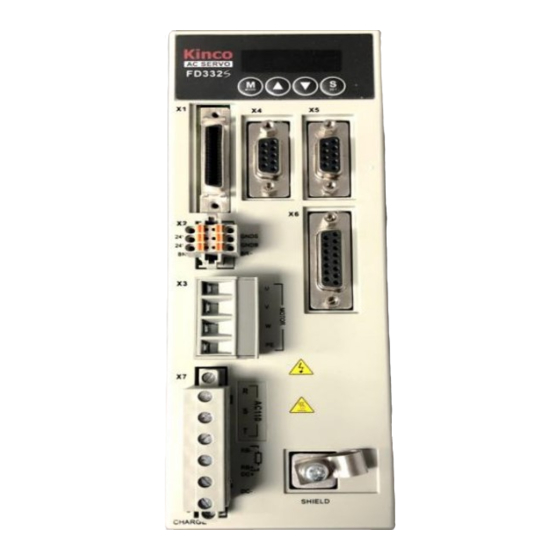
1. Remove drive from packaging and affix associated terminal plug to X2, X3 and X7
2. With the power disconnected, connect the power wires to the input terminals.
a. For FD4x2S modules, apply line voltage to R terminal on connector X7, apply Neutral
to S terminal on X7 and connect Ground to Shield screw on chassis. Leave T terminal
floating.
b. For FD3x2S modules, Apply line voltage to L (R) and Neutral to N (S) on X7 terminal.
L011933
4985 East Landon Drive Anaheim, CA 92807
Tel. (714) 992-6990
Fax. (714) 992-0471
www.kincoautomation.com
Advertisement

Related Manuals for Kinco FD4 2S Series


Summary of Contents for Kinco FD4 2S Series
- Page 1 KINCO Servo Quick Start Guide Needed: Kinco Servo Package (motor, driver, phase and encoder cables), 24V power supply, UT232R-200 Communication Cable (FDxx2S), Flat head screw driver, Kinco Servo+ Software. 1. Remove drive from packaging and affix associated terminal plug to X2, X3 and X7 2.
- Page 2 KINCO Servo Quick Start Guide 3. Connect a 24Vdc power source to 24VS and GNDS on X2, this will power the display LEDs and EEPROM logic a. For the FDxx2S models, a 24Vdc power supply is required to power the control logic of the driver b.
- Page 3 KINCO Servo Quick Start Guide 5. Connect the Encoder cable to mating terminal X6. L011933 Tel. (714) 992-6990 www.kincoautomation.com 4985 East Landon Drive Anaheim, CA 92807 Fax. (714) 992-0471...
- Page 4 7. Apply both line power and 24VOC power to the unit and the LEDs should display “FFF.F” by default. 8. Open Kinco Servo+ Software and establish communication to the driver. a. At the drop-down tabs, Select Communication > Communication Settings i.
- Page 5 KINCO Servo Quick Start Guide b. Press the “Open” Button and it should change to “Close” i. The Cable and Error buttons below the drop down menu should illuminate Green ii. If so, close out of “Communication Settings” by pressing the red “x” at the top right corner Note: If these are Red, there is an Error.
- Page 6 KINCO Servo Quick Start Guide b. In the drop down list, go to Motor > Motor Settings i. The 3rd line will say “Motor_Num” which is defaulted to value “K@”. On the “Value” column, change this to the “X#” value we found earlier.
- Page 7 KINCO Servo Quick Start Guide ii. The 2nd line will still say K@ after pressing enter. Go to drop down lists, Driver > Init Save Reboot and press “SaveMotor Parameters” then Press “Reboot”. iii. This should update the “Motor_Using” line to match the Motor_Num line and the values should update accordingly.
- Page 8 KINCO Servo Quick Start Guide 10. Set up I/O to test your system a. With the motor sitting freely, open both the I/O and basic operation (drop down list, Driver > Basic Operation). b. Clear all DIN functions by selecting the top “X” to the left of the “Simulate” text on “Digital IO Functions”...
- Page 9 KINCO Servo Quick Start Guide c. On Basic Operation Screen, set the following: i. NUM 6 “Operation Mode” change to “3: Speed Control” Note: “3” references accel/decel parameters and “-3” does not ii. NUM 10 “Profile_Acc” set to 100 rps/s iii.
- Page 10 KINCO Servo Quick Start Guide d. On Digital IO Functions Screen, set the following: i. DIN1 > Enable ii. DIN2 > Reset Errors iii. DIN3 > Invert Direction iv. DIN4 > Operate Mode Sel Note: Change these setttings by pressing the “>>” Button and checking the check box next to the command function and pressing “ok”...
- Page 11 KINCO Servo Quick Start Guide 11. Test your system a. On the Digital IO Functions screen, click the grey simulate button for DIN/Enable”. The simulate button will turn green. i. You should get motion out of your motor at 500 RPM, if there is no motion, an error has occurred.
Need help?
Do you have a question about the FD4 2S Series and is the answer not in the manual?
Questions and answers