Table of Contents
Advertisement
Quick Links
Advertisement
Table of Contents

Related Manuals for Kinco OD Series


Summary of Contents for Kinco OD Series
- Page 1 OD series servo driver user manual en.kinco.cn...
- Page 2 Preface Product Acceptance Thank you for using Kinco Servo product ! Item for Acceptance Remark Whether the model of a delivered FD series servo system is consistent Check the nameplate of a servo motor and that of a servo driver...
- Page 3 Manual version change record Version Date Version description In May 2020 The new product manual was released In Aug 2020 Table 3-6 Description of pin names of magnetoelectric encoders In Feb 2024 Add the description of encoder Cables and Power cables in Section 3.3...
-
Page 4: Table Of Contents
Catalog Catalog Preface Product Acceptance ..........................1 Parts list ..................................1 Manual version change record ...........................2 Catalog ..................................1 Chapter 1 System configuration and types .........................3 1.1 Equipment features ..............................3 1.2 Product Specifications ............................3 1.3 Description of products ............................4 1.3.1 Naming rule ..............................4 1.3.2 Nameplate instructions .......................... -
Page 5: Manual Version Change Record
Catalog 2.4.4 400W servo motor torque curve ........................15 2.4.5 750W servo motor torque curve ........................16 Chapter 3 System Interface and Wiring ........................17 3.1 Name of OD servo parts ............................17 3.2 External wiring mode ............................17 3.3 Interface and cable instruction ..........................19 3.3.1 External input output interface (... -
Page 6: Chapter 1 System Configuration And Types
Chapter 1 System configuration and types 1.1 Equipment features For customers with limited installation space, Kinco has introduced the ultra-small volume OD series driver. The modular design scheme can be quickly combined into an integrated control scheme, and customized development can be carried out according to different working conditions of users:... -
Page 7: Description Of Products
Pulse direction control Pulse + direction, CCW+CW, A +B phase (5V ~ 24V) The maximum support 115.2K baud rate, can use Kinco upper computer software link, can also RS232 use a custom protocol to communicate with the controller The maximum support 115.2K baud rate, can use the Modbus RTU protocol to communicate... - Page 8 Chapter 1 System configuration and types Figure1-2 Naming Rules of Motor Figure1-3 Naming rules for power cable Figure1-4 Encoder line naming rules...
-
Page 9: Nameplate Instructions
Chapter 1 System configuration and types 1.3.2 Nameplate instructions Figure 1-5 Description of the driver nameplate Fig. 1-6 Motor nameplate description 1.4 Configuration table of servo system Rated power Description Rated speed Servo motor Power line/Brake line Encoder line Servo driver Rated torque SMC40S-0005-30MAK-5DSU MOT-005-LL-KL-D... -
Page 10: Brake Resistance Selection Table
Chapter 1 System configuration and types 3000rpm MOT-015-LL-KL-SP-1 OD134S-EA-000 SMC80S-0075-30MBK-3DSU 2.39Nm BRA-LL-KL OD134S-LA-000 SMC60S-0020-30AAK-3DSH MOT-005-LL-KL-D 200W 3000rpm MOT-005-LL-KL-D SMC60S-0020-30ABK-3DSH OD124S-CA-000 0.64Nm BRA-LL-KL OD124S-EA-000 SMC60S-0040-30AAK-3DSH MOT-008-LL-KL-D 400W OD124S-LA-000 2500P/R 3000rpm MOT-008-LL-KL-D ENCOA-LL-KH SMC60S-0040-30ABK-3DSH Photoelectric 1.27Nm BRA-LL-KL encoder motor SMC80S-0075-30AAK-3DSH MOT-015-LL-KL-SP-1 750W OD134S-CA-000 3000rpm OD134S-EA-000... -
Page 11: Chapter 2 System Installation Requirements And Precautions
Chapter 2 System Installation Requirements and Precautions Chapter 2 System installation requirements and precautions 2.1 Application requirements of driver Please ensure this document can be provided for design engineer, operators and staffs (or machine) who is responsible to adjust and use this product Please ensure to follow requirements of this file all the time. -
Page 12: Operator's Requirements
Chapter 2 System Installation Requirements and Precautions atmospheric pressure 86kpa~106kpa Rated working altitude is below 1000 meters, when working altitude is above 1000 meters, every rise of 100 Altitude meters, need to drop 1.5% use, the maximum working altitude is 4000 meters above sea level 2.1.3 Operator’s requirements This product must be operated by electrical engineers who are familiar with instructions below:... - Page 13 Chapter 2 System Installation Requirements and Precautions ●When it is connected with machine, please use coupling and make shaft center of servo motor and machine stay in a line. When operators install servo motors, please achieve requirements of Centering centering accuracy. If centering is not accurate, there will be shock and sometimes it will make bearings and encoders.
-
Page 14: Driver Installation Size Diagram
Chapter 2 System Installation Requirements and Precautions 2.2 Driver installation size diagram Figure 2-1 OD124S-CA/LA installation size diagram Figure 2-2 OD134S-CA/LA installation size diagram... -
Page 15: External Dimensions Of Servo Motor
Chapter 2 System Installation Requirements and Precautions 2.3 External dimensions of servo motor 2.3.1 40 External dimensions of flange motor Fig. 2-3 Dimensions of 40 flange common motor Fig. 2-4 Dimensions of 40 flanged brake motor Flange Overall dimensions(mm) Shaft size(mm) Key size(mm)... -
Page 16: External Dimensions Of Flange Motor
Chapter 2 System Installation Requirements and Precautions Fig. 2-6 Dimensions of 60 Flanged Brake Motor Flange Overall dimensions(mm) Shaft size(mm) Key size(mm) Weight dimensions Servo motor Brake (KG) Hole x Depth (mm) SMC60S-0020-30MAK-3DSU 121±1.5 91±1.5 SMC60S-0020-30AAK-3DSH 134±1.5 104±1.5 SMC60S-0020-30MBK-3DSU 151±1.5 121±1.5 √... -
Page 17: Servo Motor Torque Curve
Chapter 2 System Installation Requirements and Precautions Flange Overall dimensions(mm) Shaft size(mm) Key size(mm) Brak Weight dimensions Servo motor (KG) Hole x Depth (mm) SMC80S-0075-30MAK-3DSU 163.5±1.5 128.5±1.5 SMC80S-0075-30AAK-3DSH 175±1.5 140±1.5 80x80 35±1 M6x15 SMC80S-0075-30MBK-3DSU 193±1.5 158±1.5 √ SMC80S-0075-30ABK-3DSH 222±1.5 187±1.5 2.4 Servo motor torque curve 2.4.1 50W servo motor torque curve 2.4.2 100W servo motor torque curve... -
Page 18: 200W Servo Motor Torque Curve
Chapter 2 System Installation Requirements and Precautions 2.4.3 200W servo motor torque curve 2.4.4 400W servo motor torque curve... -
Page 19: 750W Servo Motor Torque Curve
Chapter 2 System Installation Requirements and Precautions 2.4.5 750W servo motor torque curve... -
Page 20: Chapter 3 System Interface And Wiring
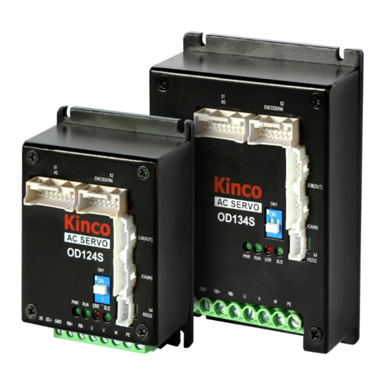
Chapter 3 System Interface and Wiring Chapter 3 System Interface and Wiring 3.1 Name of OD servo parts Figure 3–1 OD servo interface definitions 3.2 External wiring mode Figure 3-2 OD124S external connection mode... - Page 21 Chapter 3 System Interface and Wiring Note OD124S - CA/LA- 000 and OD134S LA - CA/LA - 000 drive SW1 switch for the bus terminal resistance, resistance to ON when he will be 120 euro in parallel ON the bus, to OFF when disconnected.
-
Page 22: Interface And Cable Instruction
Chapter 3 System Interface and Wiring 3.3 Interface and cable instruction 3.3.1 External input output interface (X1) Table 3-4 Interface X1 Definition Signal Description Logic power input, motor with brake must be connected Voltage: 24VDC; Current: 1A Note: Both Pin1 and Pin15 are GND, there is no 24V+ difference. - Page 23 Chapter 3 System Interface and Wiring Fig. 3-3 Wiring Diagram of External I/O Outlet Note Fig. 3-3 Output outlet is NPN connection mode, while PNP connection mode is shown in Fig. 3-4. Fig. 3-4 PNP wiring diagram of the output port...
-
Page 24: Encoder Interface (X2
Chapter 3 System Interface and Wiring 3.3.2 Encoder interface (X2) Table 3-5 Pin definition of X2 interface for motor with incremental encoder Signal Description PTC_IN Temperature sensor signal Encoder phase W singal input terminal Encoder phase W singal input terminal Encoder phase V singal input terminal Encoder phase V singal input terminal Encoder phase U singal input terminal... - Page 25 Chapter 3 System Interface and Wiring Table 3-7 Encoder cable terminal definition ENCOA-LL-KH Cable specification: 24AWG/1P+28AWG/7P+AB 1061 24AWG corresponds to a cross-sectional area of 0.2047mm 28AWG corresponds to a cross-sectional area of 0.0804mm PlaneB Three rows of 15PIN DB Double row 16PIN plastic terminals Note:...
-
Page 26: Bus Communication Interface (X3
Chapter 3 System Interface and Wiring Signal 1 Signal 2 SC-06 female Cable Double row 16PIN plastic terminals (Suitable for (Suitable for absolute (motor end) color (drive end) magnetoelectric encoder) value encoder) Black MA_P+ BAT+ Brown MA_N- BAT- Blue SLO_P+ Yellow SLO_N- Green... - Page 27 Chapter 3 System Interface and Wiring Table 3-10 CAN communication interface pin definition Pin number Pin Name Pin function CAN_H CAN_L Table 3-11 Wiring mode of CAN communication CAN plug pin definition Pin Name(Drive) Pin Number(Drive) Pin Name(PLC) CAN_H CAN_H CAN_L CAN_L Figure 3-6.
- Page 28 Chapter 3 System Interface and Wiring Table 3-12 EtherCAT communication interface pin definition Pin number Pin Name Pin function Positive received data Negaitive received data Positive send data Negaitive send data Ethercat communication port socket appearance diagram Table 3-13 Wiring mode of EtherCAT communication Drive ECAN plug Cable pin Pin Name(Drive)
-
Page 29: 232 Communication Serial Port(X4
Chapter 3 System Interface and Wiring 3.3.4 232 Communication serial port(X4) Table 3-14 RS232 communication interface pin definition Pin number Pin Name Pin function Drive send data RS232 communication port socket appearance diagram Drive received data Table 3-15 Wiring mode of RS232 communication Drive RS232 Pin Name(PC) Pin Number(PC) - Page 30 Chapter 3 System Interface and Wiring Table3-17 Power cable MOT-005-LL-KL-D MOT-008-LL-KL-D MOT-015-LL-KL-SP-1...
-
Page 31: Driver Indicator
Chapter 3 System Interface and Wiring 3.3.6 Driver indicator Table 3-18 Driver working indicator light Name Function The driver is powered on, and the POWER lamp is always on The drive is always on when ready and is associated with out3 The drive is always on when ready and is associated with out4 CANopen bus will flash when there is a message transmission, the flashing frequency is related to the transmission speed of the message... -
Page 32: Chapter 4 Working Mode Introduction
Chapter 4 Working mode introduction The RS232 interface can be connected to PC to set the parameters of OD driver. The Servo debugging software Kinco Servo+ can be downloaded from the official website of the Kinco 4.1 Trial operation Step 1: Hardware wiring Please confirm whether the hardware wiring is correct before the trial operation. -
Page 33: Velocity Mode (-3, 3)
Chapter 4 Working mode introduction the initialization, storage control parameters, control parameters to restart to complete configuration.Note that the control parameters must be initialized after the motor is configured, otherwise the phenomenon of abnormal no-load operation may occur. Table 4-1 Motor configuration parameters Internal Bits Name... -
Page 34: Analog Speed Mode
Chapter 4 Working mode introduction In software "Basic operation" window, we can find these parameters and set. Figure 4-2 Basic operation window 4.2.1 Analog speed mode The analog speed object window in the PC software can be accessed via menu item Controller->Basic operation->Control Modes->Analog Speed Mode. - Page 35 Chapter 4 Working mode introduction Default is 0, if it's NOT 0, Analog_out> 25020D10 Integer16 Analog_Dead_High Analog_Dead_High is treated as 0 Default is 0, if it's NOT 0, Analog_out< 25020E10 Integer16 Analog_Dead_Low Analog_Dead_Low is treated as 0 User defined Select the working mode according to the actual control 60600008 Integer8 Operation mode...
-
Page 36: Din Speed Mode
Chapter 4 Working mode introduction Analog_Speed_Con=1, Analog_Dead_High=0V; Analog_Dead_Low=0V; Where AIN1 input voltage is 5V: AIN1_in=5V–2V=3V, |AIN1_in| >Analog1_Dead, so Analog1_out=3V–1V=2V; Target speed=2*100=200rpm. Where AIN1 input voltage is -5V: AIN1_in=-5V–2V=-7V, |AIN1_in|>Analog1_Dead, so Analog1_out=-7V+1V=-6V; Target speed=-6*100=-600rpm. 4.2.2 DIN Speed mode The Din_Speed object window in PC software can be accessed from menu item Controller->Control Modes->DIN Speed Mode. -
Page 37: Torque Mode (4)
Chapter 4 Working mode introduction 0 means the signal is off, 1 means the signal is on. The following points need to be noted when activating DIN speed mode: 1.DIN speed mode is only available in 3 or -3 operation_mode, invalid in other working modes. 2.Analog-speed control (250207) is 0, close the analog-speed channel. -
Page 38: Analog Torque Mode
Chapter 4 Working mode introduction Table 4-7 torque mode related parameters Internal address Type Name Description Value Select the working mode according to the actual control 60600008 Integer8 Operation_mode mode. 4 is the torque mode 60710010 Integer16 Target_Torque% Target torque, percentage of rated torque User define 60400010 Unsigned16... - Page 39 Chapter 4 Working mode introduction 25020110 Unsigned16 Analog1_Filter AIN1 filter (unit: ms) 25020210 Integer16 Analog1_Dead_V AIN1 deadband (unit: 0.01V) 25020310 Integer16 Analog1_Offset_V AIN1 offset (unit: 0.01V) User 25020410 Unsigned16 Analog2_Filter AIN2 filter (unit: ms) defined 25020510 Integer16 Analog2_Dead_V AIN2 deadband (unit: 0.01V) 25020610 Integer16 Analog2_Offset_V...
-
Page 40: Position Mode (1)
Chapter 4 Working mode introduction 4.4 Position mode (1) In the position mode (1 mode), the driver control motor can be positioned in two ways: absolute position positioning and relative position positioning, and the speed and position instructions are controlled by the target position and ladder speed inside the driver. Table 4-9 location mode parameters Internal Type... - Page 41 Chapter 4 Working mode introduction 2020.12 Din_pos[6] 2020.13 Din_pos[7] Select the position segment L to be set (L range is 2FF1.01 Din_position_selectL 0-7, corresponding to the internal position segment 0-7 in turn) 2FF1.02 Din_position_M Number of pulses set in position segment (L) =M*10000+N 2FF1.03 Din_position_n...
-
Page 42: Pulse Mode (-4)
Chapter 4 Working mode introduction 4.5 Pulse mode (-4) In the pulse mode, the target velocity command is specified via the pulse input with gear ratio. Table 4-12 pulse mode related parameters Internal address Type Name Description Value 60600008 Integer8 Operation_Mode Operation mode 25080110... -
Page 43: Homing Mode (6)
Chapter 4 Working mode introduction Fig. 4-8 Illustration of Pulse Filtering 4.6 Homing mode (6) In some applications, the system requires the mechanical load to start from the same position every time it moves, so the user can satisfy this requirement by using the origin pattern.In the origin mode, the user can define an origin or zero to ensure that the mechanical load runs from the same origin each time.The operation interface of origin mode can be opened by the Menu ->... - Page 44 Chapter 4 Working mode introduction Select a home trigger under Homing Trigger. The related items appear in the configuration area. Select a suitable item according to mechanical design and wiring. The Appropriate homing_method then appears in the Pre-Set Home Method box. If Disabled is selected under homing trigger, you enter a number directly to the Pre-Set Home Method field.
- Page 45 Chapter 4 Working mode introduction Table 4-14 Introduction of various origin modes Homing_ Description Schematic Method Homing with negative position limit switch and index pulse Homing with positive position limit switch and index pulse Homing with home switch and index pulse Homing with home switch and index pulse Homing with home switch and...
- Page 46 Chapter 4 Working mode introduction Homing with positive position limit switch, home switch and index pulse Homing with positive position limit switch, home switch and index pulse Homing with positive position limit switch, home switch and index pulse Homing with negative position limit switch, home switch and index pulse Homing with negative position...
- Page 47 Chapter 4 Working mode introduction Homing with negative position limit switch, home switch and index pulse Homing with negative position limit switch Homing with positive position limit switch Homing with home switch Homing with home switch Homing with home switch...
- Page 48 Chapter 4 Working mode introduction Homing with home switch Homing with positive position limit switch and home switch Homing with positive position limit switch and home switch Homing with positive position limit switch and home switch Homing with positive position limit switch and home switch Homing with negative position limit switch and home switch...
- Page 49 Chapter 4 Working mode introduction Homing with negative position limit switch and home switch Homing with negative position limit switch and home switch 33, 34 Homing with index pulse Homing to actual position -17, -18 Homing via mechanical limit...
-
Page 50: Capter 5 Performance Adjustment
Chapter 5 Performance Adjustment Capter 5 Performance Adjustment Fig. 5-1 is the control structure diagram of the servo system. It can be seen from the diagram that the servo system generally includes three control loops: current loop, velocity loop and position loop.For the servo system, good control loop parameters can improve the service performance of the servo, can better meet the field process requirements.Therefore, it is necessary to adjust good control loop parameters. -
Page 51: Tuning Of Velocity Loop
Chapter 5 Performance Adjustment 5.1 Tuning of velocity loop Table 5-1 List of speed loop parameters Internal address Name Description Default Range Proportional velocity loop gain 60F90110 Kvp[0] Can be displayed in Hz in the PC tool can if the 1~32767 inertia ratio is right. - Page 52 Chapter 5 Performance Adjustment cause oscillation. Velocity loop feedback filter bandwidth F=Speed_Fb_N*20+100 [Hz]. Output filter adjustment The output filter is a 1st order torque filter. It can reduce the velocity control loop to output high frequency torque, which may stimulate overall system resonance. The user can try to adjust Output_Filter_N from small to large in order to reduce noise.
-
Page 53: Tuning Of Position Loop
Chapter 5 Performance Adjustment 5.2 Tuning of position loop Table 5-2 List of position loop parameters Internal address Name Description Default Range Proportional position loop gain. 60FB0110 Kpp[0] Used to set the position loop response. 0~32767 unit: 0.01Hz 0 means no feedforward, 1000 means 100% 60FB0210 K_Velocity_FF 0~100... - Page 54 Chapter 5 Performance Adjustment performance. The acceleration feedforward function can be treat as the upper controller (e.g. PLC) have a chance to directly control the torque in a position operation mode. in fact this function will expend part of the current loop response ability, so if the setting can ’ t match the position loop proportional gain and the velocity loop bandwidth, the overshot will happen.
-
Page 55: Factors Which Influence Tuning Results
Chapter 5 Performance Adjustment Table 5-3 List of notch filter parameters Internal address Name Description Default Range Used to set the frequency of the internal notch filter to eliminate mechanical resonance generated when the motor drives the 60F90308 Notch_N machine. The formula is F=Notch_N*10+100. For example, if 0~90 mechanical resonance frequency F=500 Hz, the parameter setting should be 40. -
Page 56: Capter 6 Alarms And Troubleshooting
Capter 6 Alarms and troubleshooting Capter 6 Alarms and troubleshooting When driver generate an alarm, red light, ERR, will shine. If you need more detailed information about errors and error history, please connect the controller to the PC via RS232. Table 6-1 Error status word 1 alarm code Alarm Code... - Page 57 Capter 6 Alarms and troubleshooting Connect suitable braking resistor Open software "Driver"->“Panel In case of emergency stop, there is menu”->“(F005)controller setting” no external braking resistor or braking. Correctly set "brake resistor value" an "brake resistor power" Change Connect suitable braking resistor Open software "Driver"->“Panel menu”->“(F005)controller setting”...
- Page 58 Capter 6 Alarms and troubleshooting The controller and motor together can’t match the requirement of the Change motor and driver with bigger power application 1.Reduce external pulse input frequency 2.When ensure safely use motor, increase External input pulse frequency is too "Frequency_Check"...
- Page 59 Capter 6 Alarms and troubleshooting Motor type is not auto-recognized, no Install a correct motor type to the controller and 001.0 0x6320 Motor configuration motor data in EEPROM / motor reboot never configured DIN function “pre_enable” is configured, but the input is inactive 010.0 0x5443 External enable...
-
Page 60: Appendix 1 Control Terminal Wire Making Instructions
Appendix I Cable Stamping Instructions Appendix 1 Control terminal wire making instructions OD series with the product distribution of each port of the plug terminals and pins, need to cooperate with the use of wire and DuPont terminal pressure pliers as the cable. - Page 61 Appendix I Cable Stamping Instructions Step 4: the following figure is the pressure connection terminal, it can be inserted into the corresponding terminal plug. Fig. 1 X1 and X2 interface metal pins specification...
- Page 62 Appendix I Cable Stamping Instructions Figure 2 X3 bus communication interface metal pin specifications Fig. 3 Specification of metal pins for X4RS232 communication interface Fig. 4 Schematic diagram of needle pressing Note Refer to Table 3-2 for external wiring methods in Section 3-2 for cable specifications ...
Need help?
Do you have a question about the OD Series and is the answer not in the manual?
Questions and answers