Table of Contents
Advertisement
Contents ................................................................................................................................................................... 1
Chapter 1 Product Acceptance & Model Description ............................................................................................... 4
1.1 Product Acceptance ............................................................................................................................. 4
1.1.1 Items for Acceptance (Wires Included) .............................................................................. 4
1.1.2 Nameplate of Servo Driver ................................................................................................. 4
1.1.3 Nameplate of Servo Motor ................................................................................................. 5
1.2 Component Names .............................................................................................................................. 5
1.2.1 Component Names of CD2S Servo Driver ........................................................................ 5
1.2.2 Component Names of Servo Motor ................................................................................... 6
1.3 Model Description of Servo Motors and Drivers .................................................................................. 6
1.3.1 Servo Drivers ...................................................................................................................... 6
1.3.3 Power,Brake and Encoder cable of Motors ....................................................................... 8
Chapter 2 Precautions and Installation Requirements ............................................................................................. 9
2.1 Precautions .......................................................................................................................................... 9
2.2 Environmental Conditions .................................................................................................................... 9
2.3 Mounting Direction & Spacing.............................................................................................................. 9
2.3.1 Precautions ........................................................................................................................ 9
2.3.2 Servo Driver Installation ................................................................................................... 10
Chapter 3 Interfaces and Wiring of CD2S Driver ................................................................................................... 13
3.1 Interfaces of CD2S Driver .................................................................................................................. 13
3.1.1 Interfaces .......................................................................................................................... 13
3.1.2 Wiring Diagram ............................................................................................................................... 15
3.1.3 X1 interface of CD2S Driver ........................................................................................................... 16
3.1.4 Power Interface X3 of CD2S Driver(CD432S/CD622S X3 and X7) ....................................... 17
3.1.5 X5 and X6 Interfaces of CD2S Driver ............................................................................................. 18
3.1.5.1 X5 Interface ............................................................................................................................... 18
3.1.5.2 X6 Interface ................................................................................................................ 18
Chapter 4 Digital Operation Panel .......................................................................................................................... 19
4.1 Introduction ........................................................................................................................................ 19
4.2 Operation on Digital Operation Panel ................................................................................................ 21
switching .................................................................................................................................... 21
Chapter 5 Motor Selection,Trial Operation and Parameter List ............................................................................. 24
5.1 Driver and motor configuration .......................................................................................................... 24
5.2 Trial Operation ................................................................................................................................... 27
5.2.1 Objective........................................................................................................................... 27
5.2.2 Precautions ...................................................................................................................... 27
5.2.3 Operating Steps ................................................................................................................ 28
5.2.4 Diagram of Trial Operation ............................................................................................... 28
5.3 EASY USE ......................................................................................................................................... 28
5.4 Description of Parameters ................................................................................................................. 34
Chapter 6 Operation on Input/Output Ports ........................................................................................................... 46
Contents
1
Advertisement
Table of Contents
Troubleshooting

Related Manuals for Kinco CD2S Series


Summary of Contents for Kinco CD2S Series
-
Page 1: Table Of Contents
Contents Contents ................................... 1 Chapter 1 Product Acceptance & Model Description ....................4 1.1 Product Acceptance ..........................4 1.1.1 Items for Acceptance (Wires Included) ................4 1.1.2 Nameplate of Servo Driver ....................4 1.1.3 Nameplate of Servo Motor ....................5 1.2 Component Names .......................... - Page 2 6.1 Digital Input Signals ........................... 46 6.1.1 Polarity Control on Digital Input Signals ................46 Example 6-1: Polarity Setting for Digital Input Signal DIN1 ............47 6.1.2 Simulation of Digital Input Signals ................... 47 Example 6-2: Simulate digital input DIN1 ................. 48 6.1.3 Status Display of Digital Input Signals ................
- Page 3 8.3 Auto reverse ........................95 8.4 Debugging example ........................... 96 8.4.1 Oscilloscope ........................96 8.4.2 Procedure for Parameter Adjustment ................97 Chapter 9 Communication ............................ 103 9.1 Transport Protocol ........................... 103 9.2 Data Protocol ........................... 104 9.2.1 Download(from Host to Slave) ..................104 9.2.2 Upload(From Slave to Host) ...................
-
Page 4: Chapter 1 Product Acceptance & Model Description
Chapter 1 Product Acceptance & Model Description 1.1 Product Acceptance 1.1.1 Items for Acceptance (Wires Included) Table 1-1 Product acceptance Item for Acceptance Remark Whether the model of a delivered CD2S Check the nameplate of a servo motor and series servo system is consistent with the that of a servo driver specified model Whether the accessories included in the... -
Page 5: Nameplate Of Servo Motor
1.1.3 Nameplate of Servo Motor Model Rated power Rated voltage Rated current Rated torque Rated rotation speed Insulation class Protection class Serial No. Bar code Fig. 1-2 Nameplate of a servo motor 1.2 Component Names 1.2.1 Component Names of CD2S Servo Driver... -
Page 6: Component Names Of Servo Motor
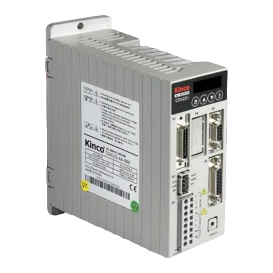
Fig. 1-3 Component Names of CD2S Servo Driver 1.2.2 Component Names of Servo Motor Fig. 1-4 Component names of a servo motor (brakes excluded) 1.3 Model Description of Servo Motors and Drivers 1.3.1 Servo Drivers 1.3.2 Servo Motors... -
Page 8: Power,Brake And Encoder Cable Of Motors
1.3.3 Power,Brake and Encoder cable of Motors... -
Page 9: Chapter 2 Precautions And Installation Requirements
Chapter 2 Precautions and Installation Requirements A Kinco CD2S series servo driver is installed on a base. If a driver is not installed properly, some faults may occur. To avoid this, install the driver by abiding by the following precautions. -
Page 10: Servo Driver Installation
2.3.2 Servo Driver Installation 1. Installing a servo driver: Fig. 2-1 Installing a servo driver 2. Installing multiple servo drivers: Ensure that there is enough space between a servo driver and the inner wall of a control cabinet. Additionally, install cooling fans at the upper part of the servo driver. To prevent localized overheating of the environmental temperature on the servo driver, you need to keep an even temperature in the control cabinet. - Page 11 Fig. 2-2 Installing multiple servo drivers 3. Other Cases Install the servo driver vertically on a wall. Take fully into account heat dissipation when using any heating components (such as braking resistors) so that the servo driver is not affected.
- Page 12 Fig. 2-3 Installation direction...
-
Page 13: Chapter 3 Interfaces And Wiring Of Cd2S Driver
Chapter 3 Interfaces and Wiring CD2S Driver 3.1 Interfaces of CD2S Driver 3.1.1 Interfaces Table 3-1 Interfaces of CD412S/CD422S/CD432S/CD622S Interface Driver Symbol Function COMI Common terminal of digital inputs DIN1~DIN7 Digital inputs. Valid signal:12.5V~24V.Invalid signal:<5V OUT1+ Digital output 1+ OUT1- Digital output 1- OUT2+ Digital output 2+... - Page 14 interface (-) 24VS/GNDS Logic power supply:‖18VDC~30VDC 1A‖ Power supply for brake ―18VDC~30VDC 0.5A‖ (CD622S 2A) 24VB/GNDB BR+/BR- Brake interface U/V/W/PE Motor cable interface Main power supply(Single-phase AC220V) CD412S CD422S RB+/RB- Braking resistor interface CD412S RS232 RS232 interface CD422S ENCODER CD432S Encoder cable interface CD622S Main power supply (...
-
Page 15: Wiring Diagram
3.1.2 Wiring Diagram Fig.3-1 Wiring diagram of CD2S driver... -
Page 16: X1 Interface Of Cd2S Driver
3.1.3 X1 interface of CD2S Driver Fig.3-2 X1 interface Fig.3-3 Wiring diagram of X1 interface... -
Page 17: Power Interface X3 Of Cd2S Driver(Cd432S/Cd622S X3 And X7
3.1.4 Power Interface X3 of CD2S Driver(CD432S/CD622S X3 and X7) CD412S/422S(AC220V) CD432S(AC220V) CD622S(AC380V) Fig.3-4 Power interface of CD2S driver... -
Page 18: X5 And X6 Interfaces Of Cd2S Driver
3.1.5 X5 and X6 Interfaces of CD2S Driver 3.1.5.1 X5 Interface Interface Signal Description Function To transmit data To receive data RS232 Ground of signal communication (9-pin female interface connector) 3.1.5.2 X6 Interface Interface Signal Description Function To output 5 V voltage PTC_IN N/A To input phase-A signals of encoder... -
Page 19: Chapter 4 Digital Operation Panel
signals of encoder Chapter 4 Digital Operation Panel 4.1 Introduction A digital operation panel functions to set user parameters in a servo driver, execute instructions, or display parameters. Table 4-1 describes all display contents and functions of the digital operation panel. Table 4-1 Display contents and functions of a digital operation panel Number/ Function... - Page 20 real time. Indicates the earliest error when history records of errors (F007) are displayed. Indicates a data display format when parameters are displayed and adjusted in real time. If it is on, it indicates the data is displayed in hexadecimal; otherwise it indicates the data is displayed ③...
-
Page 21: Operation On Digital Operation Panel
4.2 Operation on Digital Operation Panel Power ON Press MODE Switching of basic menus Parameter display (current speed is displayed by default) Press Press Set driver instructions Press Press Set real-time display of data Press Press Set control loop parameters Press I/O parameters Press... -
Page 22: Example 4-2: Set The Speed To 1000 Rpm/-1000 Rpm With Separate Regulation Of Bits
Press ENTER. The interface for selecting addresses is displayed. Press ▲ to adjust data as d3.35. Press ENTER to display the current value d3.35. Press ENTER again to modify the value d3.35. In this case, the 1 number at the right side is flickering. Short press MODE for three times to move to the first position on the left. - Page 23 Fig. 4-3 Separate regulation of bits...
-
Page 24: Chapter 5 Motor Selection,Trial Operation And Parameter List
Chapter 5 Motor Selection,Trial Operation and Parameter List 5.1 Driver and motor configuration There is no default motor type set in driver,so users need to set the motor model before using the driver.Please refer to the selection table when setting the motor model. 1. - Page 25 Note: You should download the new version software from our website: http://www.kinco.cn/en/ Fig.5-1 Data file downloading 2. Customers do not have data file(They need configure motor model in servo) Customers can configure the motor’s model according to servo/motor configuration table mentioned above, then set the parameters according to the application.
- Page 26 Fig.5-2 Flow chart for configuring motor by key Please configure the right motor’s model before restart. If customers want to reset the motor model, they should set D4.19 to 303.0 (Press ENTER to confirm) and then d4.00 to 1(Save motor parameters), after restart the servo they can reset motor model and servo parameters according to the above chart (2) Configure Motor (CD-PC Software Operation) Connect the servo to PC, open the CD-PC, then Menu—Driver—Control Panel—F004, in the F004, in...
-
Page 27: Trial Operation
Fig.5-3 Configure motor by software 5.2 Trial Operation 5.2.1 Objective The trial operation allows you to test whether the driver works properly, and whether the motor runs stably. 5.2.2 Precautions Ensure that the motor is running without load. If the motor flange is fixed on the machine, ensure that the motor shaft is disconnected from the machine. -
Page 28: Operating Steps
5.2.3 Operating Steps Press MODE to enter Group F004. Select the object address ―d4.18‖, and check the motor type. Press MODE to enter Group F000. Select the object address ―d0.02‖, and set the target speed to ―SpeedDemand_RPM". Press MODE to enter Group F006. Arrange a test for keys, with the default value of d6.40. Firstly, press ▼... - Page 29 Easy Use operation steps 1. EASY includes common parameters. Please ensure each of them one by one and save by EA00. 1.1 If motor type (EA01) does not change, set 1 to EA00 and save parameters in forward steps. 1.2 If motor type (EA01) does not change, set 2 to EA00. Then save parameters in forward steps and reboot driver.
- Page 30 EA05 Factor For controller use with standard KINCO-AS motors, the maximum value is 374, the maximum velocity is 3740rpm/10v/. For more details see chapter 9.3 (d3.29). The meaning of each digit of the LED display from right to left.
- Page 31 Users must save control and motor parameters and reboot the controller after changing the motor type in EA01. After saving the parameters, the servo will set the control loop parameters according to the load type and application. Table 2 Stiffness and control loop settings Output filter Output filter Stiffness...
- Page 32 Flowchart of EASY use function START Execute the flow chart of EASY Good Jog the machine, evaluate the performance Not good Measure the Inertia Ratio by Tn03 Adjust the Stiffness by Tn01 Can not figure out by Not Good adjusting the stiffness Jog the Machine, Adjust Gain by PC evaluate the performance...
- Page 33 EASY flowchart Note: The menu is exited automatically if there is no operation in 60s, and users have to start again. Entered data is valid immediately, but must be saved via EA00.
-
Page 34: Description Of Parameters
Flowchart for the TunE menu MODE MODE Long Press MODE adjusted by “▼▲”level by level and will be valid immediately Stiffness ▲ ▼ Long Press MODE Write automatically after inertia measuring. Or written by user. adjusted by “▼▲”level by level and will be valid immediately Inertia ratio, unit is 0.1 ▲... - Page 35 d0.00 60600008 Operation_Mode 0.004 (-4): Pulse control mode, including pulse direction (P/D) and double pulse (CW/CCW) modes. 0.003 (-3): instantaneous speed mode 0001 (1): Internal position control mode 0003 (3): Speed mode with acceleration/deceleration 0004 (4): Torque mode Note: Only applied in the working mode where no external signals control the driver.
- Page 36 starts. All input signals are neglected during auto tuning. The variable is automatically changed to 0 after auto tuning is completed. Sets the variable to other values to end auto tuning. Parameter List: Group F001 (To Set Real-Time Display Data) Numeric Internal Address Variable Name...
- Page 37 d1.25 606C0010 Real_Speed_RPM Real speed (rpm) Internal sampling time: 200 mS d1.26 60F919 Real_Speed_RPM2 Real speed (0.01 rpm) Internal sampling time: 200 mS d1.27 60F91A10 Speed_1mS Speed data (inc/1 mS) Internal sampling time: 1 mS d1.28 60F60C10 CMD_q_Buff Internal effective current instruction d1.29 60F61710 Actual current...
- Page 38 low-pass filter 1: Direct speed response without filtering 2: Feedback on output feedback d2.07 60FB0110 Proportional gains on position loop Kpp 1000 0~10000 d2.08 60FB0210 K_Speed_FF 0 indicates no feedforward, and 256 indicates 0~255 100% feedforward d2.09 60FB0310 K_Acc_FF The data is inversely proportional to the 32767 32767~1 feedforward...
- Page 39 Parameter List: Group F003 (To Set Input/Output & Pattern Operation Parameters) Numeric Internal Variable Name Meaning Default Range Display Address Value d3.00 2FF00108 Store_Loop_Data 1: Stores all control parameters except motor parameters 10: Initializes all control parameters except motor parameters d3.01 20100310 Din1_Function...
- Page 40 d3.15 20101310 Dout5_Function 001.0: Motor brake 001.0 002.0:Velocity reached 004.0: Index 008.0: The maximum speed obtained in the torque mode 010.0: PWM ON 020.0: Position limiting 040.0: Reference found 080.0: Reserved 100.0: Multi Dout 0 200.0: Multi Dout 1 400.0: Multi Dout 2 d3.16 20200D08 Din_Mode0...
- Page 41 Valid in mode -3, 3 and 1. d3.29 25020A10 Analog_Speed_Fa Sets the proportion between analog signals 1000 ctor and output speed d3.30 25020808 Analog_Torque_C Chooses analog-torque channels 0: Invalid analog channel 1: Valid analog channel 1 (AIN1) 2: Valid analog channel 2 (AIN2) Valid mode 4 d3.31 25020B10...
- Page 42 d3.41 2FF10210 Din_Position_M Refer to d3.42 d3.42 2FF10310 Din_Pos L(Pulse number) Din_Position_N Din_Position_M *10000+ Din_Position_N Input ―Enable‖ signal controls the control d3.43 20200F10 Din_Control_Word word. d3.44 20201810 Din_Speed4_RPM Multi-speed control: 4 [rpm] d3.45 20201910 Din_Speed5_RPM Multi-speed control: 5 [rpm] d3.46 20201A10 Din_Speed6_RPM Multi-speed control: 6 [rpm]...
- Page 43 Kt[Nm/Arms]*100 d4.14 64101010 Jr_Motor Indicates the rotor inertia of motors Jr[kgm^2]*1 000 000 d4.15 64101110 Brake_Duty_Cycle Indicates the duty cycle of contracting brakes 0~2500[0…100%] d4.16 64101210 Brake_Delay Indicates the delay time of contracting brakes Default value: 150 ms d4.17 64101308 Invert_Dir_Motor Indicates the rotation direction of motors d4.18...
- Page 44 Parameter List: Group F005 (To Set Driver Parameters) Numeri Internal Variable Name Meaning Default Note Address Value Display d5.00 2FF0010 Store_Loop_Data 1: Stores all control parameters except motor parameters 10: Initializes all control parameters except motor parameters d5.01 100B000 ID_Com Station No.
- Page 45 360 V adjust Note:Factory parameters d5.11 60F6061 Comm_Shift_UVW Indicates the excitation pointer of a motor Please don’t Note:Factory parameters adjust d5.12 2600001 Error_Mask Indicates error masks FFF.F Please don’t Note:Factory parameters adjust d5.13 60F7051 RELAY_Time Indicates the relay operating time of capacitor short-circuits Unit: mS Note:Factory parameters...
-
Page 46: Chapter 6 Operation On Input/Output Ports
Chapter 6 Operation on Input/Output Ports KINCO CD2S servo driver has 7 digital input ports (a digital input port can receive high-level or low-level signals, depending on whether high-level or low-level signals are chosen at the COM terminal) and 5 digital... -
Page 47: Example 6-1: Polarity Setting For Digital Input Signal Din1
Example 6-1: Polarity Setting for Digital Input Signal DIN1 Fig. 6-1 Polarity setting for digital input signal DIN1 Table 6-3 Polarity setting for digital input signal DIN1 ① ② ③ ④ Input/output port selection Channel selection Reserved 0: D1N1 is enabled when S1 Set to 1 (input port Set to 1 (DIN 1 selected) opens... -
Page 48: Example 6-2: Simulate Digital Input Din1
Example 6-2: Simulate digital input DIN1 Table 6-6: Simulate digital input DIN1 ① ② ③ ④ Input/output port selection Channel selection Reserved 0: Invalid DIN1 simulation Set to 1 (input port Set to 1 (DIN 1 selected) 1: Valid DIN1 simulation selected) Namely, if d3.09 is set to ―110.0‖, it indicates that no DIN1 input signals are simulated;... - Page 49 400.0: Activate command Note:DinX_Function (X ranges from 1 to 7) is used to define the functions of digital input ports. User can freely define the functions of the digital input ports according to actual applications. Table 6-9 Meaning of defined functions of digital input signals Function Meaning Disable...
-
Page 50: Multiple Electronic Gear Ratio Switch Function And Multiple Gain Switch Function
Activate command When the rising edge of the signal is detected,it will activate the internal position control 6.1.5 Multiple electronic gear ratio switch function and multiple gain switch function 1. Multiple electronic gear ratio switch function Multiple electronic gear ratio is determined by combined with Multi Din 0, Multi Din 1 and Multi Din 1 defined in I/O.For electronic gear molecular (0~7) and electronic gear denominator (0~7), the default value is 1000. -
Page 51: Example 6-3: Driver Enable Setting
The 0 gain Kvp 0 60F90110 Kvi 0 60F90210 Kpp 0 60FB0110 The 1 gain Kvp 1 23400410 Kvi 1 23400510 Kpp 1 23400610 The 2 gain Kvp 2 23400710 Kvi 2 23400810 Kpp 2 23400910 The 3 gain Kvp 3 23400A10 Kvi 3 23400B10... -
Page 52: Example 6-5: Operation Mode Control On Drivers
Display d3.05 Din5_Function Change the default value 001.0 (position positive limit) to 000.0 d3.06 Din6_Function Change the default value 002.0 (position negative limit) to 000.0 d3.00 Store_Loop_Data Set to 1 Example 6-5: Operation Mode Control on Drivers Requirements: Defines the input port DIN3 as the operation mode control on drivers, and the operation mode is ―-4‖... -
Page 53: Digital Output Signals
PNP wiring diagram (to the controller that supports high level output) Fig. 6-3 PNP wiring diagram (to the controller that supports high level output) 6.2 Digital Output Signals 6.2.1 Polarity Control on Digital Output Signals Table 6-14 Variables for setting simplified IO polarity Numeric Variable Name Meaning... -
Page 54: Status Display Of Digital Output Signals
Display Value d3.09 Dio_Simulate Simulates input signals, and the output signal is outputted compulsorily Dio_Simulate (IO simulation) is to simulate the output of a valid signal. The number ―1‖ indicates that the output signal is valid, and ―0‖ indicates that the output signal is invalid. 6.2.3 Status Display of Digital Output Signals Table 6-16 Variables for status display of digital output signals Numeric Display... -
Page 55: Example 6-6: -Ready‖ Settings
unchanged in the window (d3.39) of the time of reaching the target position, and position errors are within the window of reaching the target position. Zero velocity After the motor is enabled, it is outputted when the motor speed is 0. Motor brake The driver enables the motor, and contracting brake output is valid. - Page 56 Fig. 6-4 Internal circuit diagram of digital output ports Note: To apply the OUT3 or OUT4 port, the COMO port must be connected. To apply the BR+/BR- port, both the 24VO and COMO ports must connect to the external input power. NPN wiring (to controllers that support valid low level input) Fig.
- Page 57 Fig. 6-6 PNP wiring diagram (to controllers that support valid low level input) To connect a relay to the digital output port, do remember to connect a diode in inverse parallel, as shown in Fig. 6-7. Fig. 6-7 Connect a relay to the digital output port (Reverse parallel connect diode) Note: When OUT3 and OUT4 are used, COM0 must be connected.
-
Page 58: Chapter 7 Mode Operation
Chapter 7 Mode Operation 7.1 Pulse Control Mode (“-4” Mode) 7.1.1 Wiring in Pulse Control Mode 1. Wiring diagram of CD2S driver in pulse control mode Fig. 7-1 Wiring diagram of CD2S driver in pulse control mode 2.Common anode connection (to controllers that support valid low level output) Fig. -
Page 59: Parameters For Pulse Control Mode
3. Common cathode connection (to controllers that support valid high level output) Fig. 7-4 Common cathode connection (to controllers that support valid high level output) 7.1.2 Parameters for Pulse Control Mode Parameters for electronic gear ratio Table 7-1 Parameters for electronic gear ratio Numeric Variable Name Meaning... - Page 60 Display Value d3.36 PD_CW 0: Double pulse (CW/CCW) mode 1. Pulse direction (P/D) mode 2. Incremental encoder mode Note: To change this parameter, you need to save it with d3.00, and restarts it later. Note: CD series doesn’t support AB phase signal. Double pulse (CW/CCW) mode (d3.36 = 0) Effective rising edge...
- Page 61 Table 7-3 Parameters for pulse filtering coefficient Numeric Variable Meaning Default Range Display Name Value d3.37 PD_Filter Used to smooth the input pulses. 1~3276 Filter frequency: f = 1000/(2π* PD_Filter) Time constant: T = PD_Filter/1000 Unit: S Note: If you adjust this parameter during the operation, some pulses may be lost.
-
Page 62: Examples Of Pulse Control Mode
Velocity feedforward of the position loop K_Velocity_FF : the velocity feedforward of a position loop can be increased to reduce position following errors. When position signals are not smooth, if the velocity feedforward of a position loop is reduced, motor oscillation during running can be reduced. Acceleration feedback of the position loop K_Acc_FF (adjustment is not recommended for this parameter): If great gains of position loops are required, the acceleration feedback K_Acc_FF can be properly adjusted to improve performance. -
Page 63: Example 7-1: Pulse Control Mode --4‖ - Enable The Driver Through External Digital Input
please disable the function of limit switches by referring to Example 6-4. Step 3: Confirm mode switching bits and operation modes by referring to the settings in Example 6-5. The factory default settings of the driver are as follows: When no signal is inputted on DIN3, the driver operates in the ―-4‖... -
Page 64: Example 7-2 Pulse Control Mode --4‖ - Enable The Driver Automatically After Driver Power On
―d3.00‖, and restarts it later. d3.00 Store_Loop_Data 1: Storing all configured parameters Set to 1 for the control loop 10: Initializing all parameters for the control loop Example 7-2 Pulse control mode “-4” – enable the driver automatically after driver power on Requirement: The auto power-on function of the driver is enabled, DIN2 is used for error resetting, and DIN3 controls the operation modes of a driver (the mode is ―-4‖... -
Page 65: Speed Mode ("-3" Or "3" Mode)
1. Pulse direction (P/D) mode (pulse direction) Note: To change this parameter, you need to save it with the address ―d3.00‖, and restarts it later. d3.00 Store_Loop_Data 1: Storing all configured parameters Set to 1 for the control loop 10: Initializing all parameters for the control loop 7.2 Speed Mode (“-3”... -
Page 66: Wiring In Analog - Speed Mode
7.2.1 Wiring in Analog – Speed Mode Fig. 7-6 Wiring diagram of CD2S Servo in analog–speed mode 7.2.2 Parameters for Analog – Speed Mode Table 7-9 Parameters for analog – speed mode Numeric Variable Name Meaning Default Range Display Value d3.22 Analog1_Filter Used to smooth the input analog signals. -
Page 67: Analog Signal Processing
d3.28 Analog_Speed_Con Chooses analog-speed channels 0: Invalid analog channel 10~17 1: Valid analog channel 1 (AIN1) 20~27 2: Valid analog channel 2 (AIN2) 10~17:AIN1 for ―Din_Speed (X-10)‖ 20~27:AIN2 for ―Din_Speed (X-20)‖ Valid in mode -3, 3 and 1. d3.29 Analog_Speed_Factor Sets the proportion between analog signals and output speed d3.32... -
Page 68: Torque Mode ("4" Mode)
being powered on. In this case, the numeric display has limit status display. If limit switches are unavailable, please disable the function of limit switches by referring to Example 6-4. Step 3: Confirm the mode switching positions and operation modes by referring to the settings in Example 6-5. The factory default settings are as follows: When no signal is inputted to DIN3, the driver operates in the ―-4‖... -
Page 69: Analog Signal Processing
d3.23 Analog1_Dead Sets dead zone data for external analog 0~10V signal 1 d3.24 Analog1_Offse Sets offset data for external analog -10~1 signal 1 d3.25 Analog2_Filter Used to smooth the input analog 1~127 signals. Filter frequency: f=4000/(2π* Analog1_Filter) Time Constant (T) = Analog2_Filter/4000 (S) d3.26 Analog2_Dead... -
Page 70: Examples Of Analog - Torque Mode
SMH40S-0010-30AXK-4LKH 0.265 SMH60S-0020-30AXK-3LKX 0.48 SMH60S-0040-30AXK-3LKX 0.48 SMH80S-0075-30AXK-3LKX 0.662 CD422S-AA-000 SME60S-0020-30AXK-3LKX 0.48 SME60S-0040-30AXK-3LKX 0.48 SME80S-0075-30AXK-3LKX 0.662 SMH80S-0100-30AXK-3LKX 0.562 SMH110D-0105-20AXK-4LKX 0.992 SMH110D-0126-20AXK-4LKX 1.058 CD432S-AA-000 27.5 SMH130D-0105-20AXK-4HKX 1.1578 SMH130D-0157-20AXK-4HKX 1.191 SMH110D-0126-30AXK-4HKX 1.058 SMH110D-0157-30AXK-4HKX 0.992 SMH110D-0188-30AXK-4HKX 1.058 SMH130D-0105-20AXK-4HKX 1.1578 CD622S-AA-000 SMH130D-0157-20AXK-4HKX 1.191 SMH130D-0210-20AXK-4HKX 1.3232 SMH150D-0230-20AXK-4KHX 1.65 7.3.4 Examples of Analog –... - Page 71 Table 7-18 Parameter settings in Example 7-7 Numeric Variable Name Meaning Parameter Settings Display d3.01 Din1_Function Defines the functions of 000.1 (Driver enable) digital input port 1 d3.02 Din2_Function Defines the functions of 000.2 (Error resetting) digital input port 2 d3.03 Din3_Function Defines the functions of...
-
Page 72: Internal Multi-Position Control Modes ("1" Mode)
Initializing parameters control loop 7.4 Internal Multi-position Control Modes (“1” Mode) In Internal Multi-position control mode, we can activate internal set target position though an external signal to control motors. The activation has two preconditions: control mode can only be activated in Mode 1, it can’t be activated in other modes. Multi-position 2, At least one of the external input signal is defined as ―Internal position control 0‖, ―Internal position control 1 ―... -
Page 73: Example7-3: Internal Multi-Position Control Mode
Example7-8: Internal Multi-position control mode A motor needs to go eight position sections. In position section 0, it should reach the 5000 pulse location at the speed of 100RPM.In position section 1, it should reach the 15000 pulse location at the speed of 150RPM.In position section 2, it should reach the 28500 pulse location at the speed of 175RPM.In position section 3, it should reach the -105000 pulse location at the speed of 200RPM. - Page 74 d3.00 Storage parameters 1(Storage configuration parameters) 2. Set position and speed: Table 7-23 Internal Multi-position and Speed Configuration Numberic Variable Name Parameters Settings display d3.43 Relative / Absolute position selection Set to 2F(absolute location) Multi-position control L(The range of L d3.40 which presents...
-
Page 75: Internal Multi-Speed Control Modes ("-3" Or "3" Mode)
section 5 to 325) Set position M (M*10000) d3.41 Set to 0 Set to 850 (Set the position of d3.42 Set position N section 6 to 850) Set to 275 (Set the speed of d3.46 Set the speed of position section 6 section 6 to 275) Set position M (M*10000)... -
Page 76: Example 7-4: Internal Multi-Speed Control
Multi-speed control d3.20 2 [rpm] Din_Speed2_RPM Multi-speed control d3.21 3 [rpm] Din_Speed3_RPM Note: If you need to set the target speed precisely, it is required to set Din_Speed0, Din_Speed1, Din_Speed2 and Din_Speed3 with a host computer. The four data units are internal units and are suitable for users who are familiar with drivers. -
Page 77: Homing Mode ("6" Mode)
d3.02 Set to 000.4 Din2_Function (control over operation modes of drivers) d3.06 Set to 010.0 Din6_Function (internal speed control 0) d3.07 Set to 020.0 Din7_Function (internal speed control 1) d3.16 Set to 0.003 (3) mode Din_Mode0 (speed mode with acceleration/deceleration) d3.17 Set to 0.003 (-3) mode Din_Mode1... - Page 78 0x607C0020 Home_Offset Home offset In Homing mode, set the offset relative to the zero point. 0x60980008 Homing_Method Homing method Select the homing method 0x60990120 Homing_Speed_Switch Speed for searching Set the speed for searching the limit the limit switch switch which defined as homing signal. 0x60990220 Homing_Speed_Zero Speed for searching...
- Page 79 Methods 3 and 4: Homing on the positive home switch and index pulse Using methods 3 or 4, the initial direction of movement is dependent on the state of the home switch. The home position is at the index pulse to either the left or right of the pint where the home switch changes state.
- Page 80 Methods 7 to 14: Homing on the home switch and index pulse These methods use a home switch that is active over only a portion of the travel; in effect the switch has a ―momentary‖ action as the axle position sweeps past the switch. Using methods 7 to 10, the initial direction of movement is to the right, and using methods 11 to 14, the initial direction of movement is to the left, except if the home switch is active at the start of motion.
- Page 81 Methods 15 and 16: Reserved These methods are reserved for future expansion of the homing mode. Methods 17 to 30: Homing without an index pulse These methods are similar to methods 1 to 14, except that the home position is not dependent on the index pulse;...
- Page 83 Methods 31 and 32: Reserved These methods are reserved for future expansion of the homing mode. Methods 33 and 34: Homing on the index Method 35: Homing on the current position In this method, the current position is taken to be the home position. Methods -17 and -18: Use the mechanical terminal as reference point...
-
Page 84: Example 7-5:Using Method 7 For Homing
Example 7-5:Using method 7 for homing. 1. Set parameters. Numberic display Parameter Name meaning Setting Value 000.1 d3.01 Din1_Function (Driver enabled) 000.2 d3.02 Din2_Function (Driver error reset) 000.1: Driver enabled 000.4 000.2: Driver error reset d3.03 Din3_Function (Driver model control) 000.4: Operation mode 200.0... - Page 85 motor At this time, computer software shows: Notice: The positive and negative limits are default to normally closed point. Otherwise, the Panel will alarm and display P.L (positive limit) and N.L (No limit). Only when the alarm is eliminated, the origin control mode can be normally used.
- Page 86 In common circumstance, only need to set up the model of origin and the rest of the parameters are default. In some case, ―Electrify and then find the origin‖ is set to 1, at the same time the definition-- ―Start finding the origin‖...
- Page 87 Note: ―Start finding the origin‖ signal is a pulse signal, requires only a rise, not need to always be on. If you want to start next time, a rise pulse is enough. (4). After the external find the origin, computer monitoring picture is as follows:...
- Page 88 (5). Driver searches the Z phase signal in mode 7, and ultimately find the origin. Computer monitoring picture is shown as follows: In mode 7, it is default to detect z phase signal after searching the origin decline along. Computer monitoring...
- Page 89 picture is shown as follows: At this point, you have completed the origin search function, then the drive position is automatically set to zero, and the current position is default to origin. Computer monitoring picture is as shown:...
-
Page 90: Chapter 8 Control Performance
Chapter 8 Control Performance 8.1 Driver Performance Tuning Fig. 8-1 Schematic diagram for control loop adjustment As shown in Fig. 8-1, a typical servo system contains three control loops, namely, a position loop, a velocity loop, and a current loop. Current loops are related to motor parameters (optimal parameters of the selected motor are default for the driver and no adjusting is required). - Page 91 d2.05 Speed_Fb_N Reduces the noise during motor operation 0~45 by reducing the feedback bandwidth of velocity loops (smoothing feedback signals of encoders). When the set bandwidth becomes smaller, the motor responds slower. The formula is F=Speed_Fb_N*20+100. For example, to set the filter bandwidth to "F = 500 Hz‖, you need to set the parameter to 20.
- Page 92 Left 2 Right 2 Left 3 Right 3 Left 4 Right 4 Fig. 8-2 Schematic diagram of gain adjustment of velocity loop Step 2: Adjust parameters for feedback filter of velocity loop During gain adjustment of a velocity loop, if the motor noise is too great, you can properly reduce the parameter Speed_Fb_N for feedback filter of the velocity loop;...
- Page 93 of velocity loop; otherwise oscillation may occur. The formula for calculating the bandwidth of feedback filter of velocity loop is F = Speed_Fb_N*20+100 (Hz). 2. Parameters for position loop Table 8-2 Parameters for position loop Numeric Variable Name Meaning Default Range Display Value...
-
Page 94: Oscillation Inhibition
Table 8-3 Parameters for pulse filtering coefficient Numeric Variable Meaning Default Range Display Name Value d3.37 PD_Filter Used to smooth the input pulses. 1~32767 Filter frequency: f = 1000/(2π* PD_Filter) Time constant: T = PD_Filter/1000 Unit: S Note: If you adjust this filter parameter during the operation, some pulses may be lost. -
Page 95: Auto Reverse
8.3 Auto reverse In this mode,motor will run forward and reverse continuously according to the setting mode.User can set parameters in velocity loop and position loop in this mode.Please make sure auto forward/reverse is allowed in the machine before using this mode and make sure the power of driver can be cut off anytime to avoid accident. -
Page 96: Debugging Example
8.4 Debugging example 8.4.1 Oscilloscope 1. Enter oscilloscope 2. Parameters for Oscilloscope... -
Page 97: Procedure For Parameter Adjustment
8.4.2 Procedure for Parameter Adjustment 1.Velocity Loop Adjustment (1) Adjust Kvp according to the load. ① Set motor running at Auto Reverse mode by position(Operation mode -3),then open oscilloscope and set the parameters to observe the curve.As shown in following figures. ②... - Page 98 In Auto Reverse mode,Kvp=110...
- Page 99 The oscilloscope is shown as follows:actual speed response is 10.00ms 2.Position Loop Adjustment (1) Adjust Kpp. (2)Adjust Vff(K_Velocity_FF) Adjust Vff parameter according to the allowable position error and coupling performance of machine. Normally Vff is 100%.If system doesn’t need high response for position,then this parameter can be decreased to reduce overshoot.
- Page 100 The oscilloscope is as following: max. following error is 69 inc. Fig.(2) Kpp=30,Vff=100%...
- Page 101 The oscilloscope is as following:max. following error is 53 inc. Fig.(3) Kpp=30,Vff=50%...
- Page 102 The oscilloscope is as following:max. following error is 230 inc.
-
Page 103: Chapter 9 Communication
Chapter 9 Communication CD2S servo driver has the RS232 communication interface, which directly controls the working of the servo driver with the operation software of a host computer. If the servo driver needs to communicate with a Programmable Logic Controller (PLC) or other controllers via the free RS485 communication interface, should be added on the driver side. -
Page 104: Data Protocol
Note: Each 10-byte packet has its own CHKS. If the host sends an ID not existed in the network to the CD2S servo driver, no CD2S servo driver will make a reply. After the host sends the data correctly, the slave will find the data packets in compliance with its own ID and check the CHKS value. -
Page 105: Upload(From Slave To Host)
9.2.2 Upload(From Slave to Host) Upload refers to that the master sends a command to read object address in the slave and the master will generate an error if a non-existent target address is uploaded. The master sends: byte 0 byte 1 byte 2 byte 3 byte 4 byte 5 byte 6 byte 7 INDEX RESERVED INDEX... - Page 106 Homing_Metho Homing_Speed_Zero 60980008 01 2F 98 60 00 21 00 00 00 B7 fault unit is DEC, Homing_Speed_ 60990120 200RPM 01 23 99 60 01 55 55 08 00 30 DEC=[(RPM*512*E Switch ncoder Homing_Speed_ 60990220 150RPM 01 23 99 60 02 00 40 06 00 9B resolution)/1875] Zero 60400010...
- Page 107 oder Resolution)/1875] Default unit of Profile acc/dec , 610.352 60840020 Profile_Dex Default rps/s DEC=[(RPS/S*65536* Encoder Resolution)/1000/ 4000] Note: Under communication mode, data are transmitted in HEX.
-
Page 108: Chapter 10 Troubleshooting
Chapter 10 Troubleshooting 10.1 Alarm Messages Digital flickering on the display indicates that an alarm occurs indicating that the driver is faulty. For details about faults, see Table 10-1 ―Fault codes‖. A code of the alarm message is represented by a hexadecimal data, and four numeric displays appear. -
Page 109: Alarm Causes & Troubleshooting
10.2 Alarm Causes & Troubleshooting Alarm Alarm Information Alarm Cause Troubleshooting code FFF.F There is no motor type set in servo No motor configured Set the motor type in d4.01. /800.0 driver 000.1 Internal Internal problem Please contact manufacturer Encoder ABZ signal cable 000.2... -
Page 110: Chapter11 Appendix
Chapter 3.4. Commutation UVW signal of encoder cable 400.0 Check encoder cable. problem EEPROM Error Because of updating firmware. Initialize all control parameters and 800.0 Driver internal problem. save,then restart driver. Contact manufacturer. Driver abnormal working Logic power supply problem. Check 24VDC power supply. -
Page 111: Appendix 2:Selection Table For Fuse
2.3kw Note:Please set brake resistor value and power in d5.04 and d5.05 when using brake resistor. Please select brake resistor power according to real application. Appendix 2:Selection Table for Fuse Driver Model Driver Power[W] Specification 200W 3.5A/250VAC CD420-AA-000 400W 7A/250VAC CD422-AA-000 750W 15A/250VAC...
Need help?
Do you have a question about the CD2S Series and is the answer not in the manual?
Questions and answers