Table of Contents
Advertisement
Advertisement
Table of Contents

Related Manuals for GeoMax Zoom40 Series


Summary of Contents for GeoMax Zoom40 Series
- Page 1 GeoMax Zoom40 Series User Manual Version 1.1 English...
- Page 2 Read carefully through the User Manual before you switch on the product. Product identification The model and serial number of your product are indicated on the type plate. Always refer to this information when you contact your agency or GeoMax authorised service workshop. Trademarks Windows is a registered trademark of Microsoft Corporation in the United States and other •...
- Page 3 0015117_001 Do NOT remove the battery during operation of the instrument, or during the shutdown pro- cedure. This can result in a file system error and data loss! Always switch off the instrument by tapping the Windows button in the bottom bar followed by Shut down from the menu.
-
Page 4: Table Of Contents
Table of Contents Safety Directions General Definition of Use Limits of Use Responsibilities Hazards of Use Laser Classification 1.6.1 General 1.6.2 Labelling 1.6.3 Distancer, Measurements without Reflectors (NP mode) 1.6.4 Distancer, Measurements with Reflectors 1.6.5 Red Laser Pointer 1.6.6 Laser Plummet Electromagnetic Compatibility EMC FCC Statement, Applicable in U.S. - Page 5 Care and Transport Transport Storage Cleaning and Drying Technical Data Angle Measurement Distance Measurement with Reflectors Distance Measurements without Reflectors (Reflectorless mode) Conformity to National Regulations 9.4.1 Zoom40 9.4.1.1 Dangerous Goods Regulations 9.4.2 Internal battery ZBA301 General Technical Data of the Product Scale Correction Reduction Formulas Software Licence Agreement...
-
Page 6: Safety Directions
Safety Directions General Description The following directions enable the person responsible for the product, and the person who actually uses the equipment, to anticipate and avoid operational hazards. The person responsible for the product must ensure that all users understand these directions and adhere to them. -
Page 7: Limits Of Use
Responsibilities Manufacturer of the prod- GeoMax AG, CH-9443 Widnau, hereinafter referred to as GeoMax, is responsible for supplying the product, including the user manual and original accessories, in a safe condition. Person responsible for the... - Page 8 DANGER Risk of electrocution Because of the risk of electrocution, it is dangerous to use poles, levelling staffs and extensions in the vicinity of electrical installations such as power cables or electrical railways. Precautions: ▶ Keep at a safe distance from electrical installations. If it is essential to work in this environ- ment, first contact the safety authorities responsible for the electrical installations and fol- low their instructions.
- Page 9 WARNING Lightning strike If the product is used with accessories, for example masts, staffs, poles, you may increase the risk of being struck by lightning. Precautions: ▶ Do not use the product in a thunderstorm. CAUTION Inappropriate mechanical influences to batteries During the transport, shipping or disposal of batteries it is possible for inappropriate mechanical influences to constitute a fire hazard.
-
Page 10: Laser Classification
Always prevent access to the product by unauthorised per- sonnel. Product-specific treatment and waste management information is available from GeoMax WARNING Only GeoMax authorised service workshops are entitled to repair these products. Laser Classification 1.6.1 General General... -
Page 11: Labelling
Type: ZBA301 Art.No.: 794086 Li-Ion Battery: 7.4V /4.4Ah 10A 33Wh GeoMax AG, CH-9443 Widnau MH4 9 0 0 9 4W L 5 Manufactured: 20XX S.NO.: 123456 Made in China 015393_001 1.6.3... - Page 12 Direct intrabeam viewing may be hazardous (low eye hazard level), in particular for deliberate ocular exposure. The beam may cause dazzle, flash-blindness and after-images, particularly under low ambient light conditions. The risk of injury for laser class 3R products is limited because of: unintentional exposure would rarely reflect worst case conditions of (e.g.) beam alignment with the pupil, worst case accommodation,...
-
Page 13: Distancer, Measurements With Reflectors
Laser beam 0015119_002 Laser beam 1.6.4 Distancer, Measurements with Reflectors General The EDM module built into the product produces a visible laser beam which emerges from the telescope objective. The laser product described in this section is classified as laser class 1 in accordance with: IEC 60825-1 (2014-05): “Safety of laser products”... -
Page 14: Red Laser Pointer
1.6.5 Red Laser Pointer General The laser pointer built into the product produces a visible red laser beam which emerges from the telescope objective. The laser product described in this section is classified as laser class 3R in accordance with: IEC 60825-1 (2014-05): “Safety of laser products”... -
Page 15: Laser Plummet
Laser beam 0015119_002 Laser beam 1.6.6 Laser Plummet General The laser plummet built into the product produces a visible red laser beam which emerges from the bottom of the product. The laser product described in this section is classified as laser class 2 in accordance with: IEC 60825-1 (2014-05): “Safety of laser products”... -
Page 16: Electromagnetic Compatibility Emc
WARNING Electromagnetic radiation can cause disturbances in other equipment. Although the product meets the strict regulations and standards which are in force in this respect, GeoMax cannot completely exclude the possibility that other equipment may be distur- bed. Safety Directions... -
Page 17: Fcc Statement, Applicable In U
Although the product meets the strict regulations and standards which are in force in this respect, GeoMax cannot completely exclude the possibility that the product may be disturbed by intense electromagnetic radiation, for example, near radio transmitters, two-way radios or diesel generators. -
Page 18: Ices-003 Statement, Applicable In Canada
Consult the dealer or an experienced radio/TV technician for help. • WARNING Changes or modifications not expressly approved by GeoMax for compliance could void the user's authority to operate the equipment. ICES-003 Statement, Applicable in Canada WARNING This Class (B) digital apparatus complies with Canadian ICES-003. -
Page 19: Description Of The System
Description of the System System Components Main components Component Description Zoom40 instrument An instrument for measuring data. Ideally suited for tasks from simple surveys to complex applications. Firmware The firmware package installed on the instrument. Consists of a standard base operating system. Container Contents Container contents Battery charger... -
Page 20: Instrument Components
Instrument Components Instrument components part 1 of 2 Detachable carrying handle with mounting screw Optical sight Objective with integrated Electronic Distance Meas- urement (EDM). Exit for EDM laser beam Vertical drive Compartment for USB cable port and USB host port Leveling bubble Keyboard 003841_001... -
Page 21: User Interface
User Interface Keyboard Alphanumeric keyboard Alphanumeric keypad Page key FNC key ESC key Navigation key ON key / Enter key Function keys F1 to F4 007380_001 Keys Description Alphanumeric keypad for entry of text and numerical values. ON key. Turns on instrument. Enter key. -
Page 22: Screen
Screen Screen Status icons Title of screen Fields Softkeys 007386_002_en ☞ All shown screens are examples. It is possible that local firmware versions are dif- ferent to the basic version. Status Icons Description The icons provide status information related to basic instrument functions. Depending on the firmware version, different icons may be displayed. -
Page 23: Softkeys
Icon Description FOIL EDM mode for measuring to sticker targets. Tap the icon to open the EDM SETTINGS screen. Indicates that a user defined custom target has been set. Keypad is set to numeric mode. Keypad is set to alphanumeric mode. Indicates that telescope position is face I. -
Page 24: Operating Principles
Operating Principles Turn instrument on Press the ON key. Turn instrument off Return to WinCE main screen. Tap on the Windows icon in task bar to shut down the Zoom40. Alphanumeric keypad The alphanumerical keypad is used to enter characters directly into editable fields. Numeric fields: Can only contain numerical values. - Page 25 In this example selecting 3 on an alphanumeric keyboard would start Tools. User Interface...
-
Page 26: Operation
Operation Instrument Setup Description This topic describes an instrument setup over a marked ground point using the laser plummet. It is always possible to set up the instrument without the need for a marked ground point. ☞ Important features It is always recommended to shield the instrument from direct sunlight and avoid uneven •... - Page 27 Setup step-by-step 03851_001 Extend the tripod legs to allow for a comfortable working posture. Position the tripod over the marked ground point, centring it as best as possible. Fasten the tribrach and instrument onto the tripod. Turn on the instrument, and, if tilt correction is set on, the laser plummet activates auto- matically, and the Level up screen appears.
-
Page 28: Working With The Battery
It is normal for the battery to become warm during charging. Using the chargers recom- • mended by GeoMax, it is not possible to charge the battery if the temperature is too high. For new batteries or batteries that have been stored for a long time (> three months), it is •... -
Page 29: Survey Application
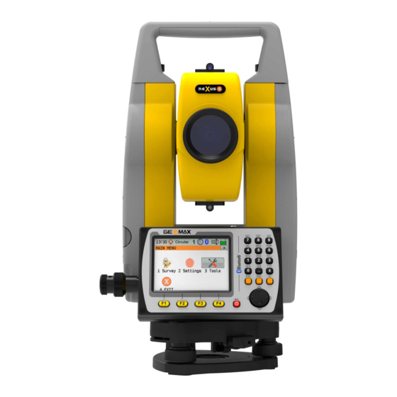
MAIN MENU Description of the MAIN MENU functions Function Description 1 Survey To select and start the survey application. Refer to "4.4 Sur- vey Application". 2 Settings To select and start Settings. Refer to "5 Settings". 3 Tools To select and start Tools. Refer to "6 Tools". 4 EXIT To exit Zoom40 Basic application. -
Page 30: Distance Measurements - Guidelines For Correct Results
Distance Measurements - Guidelines for Correct Results Description A laser distancer (EDM) is incorporated into the Zoom40 instruments. In all versions, the dis- tance can be determined by using a visible red laser beam which emerges coaxially from the telescope objective. There are two EDM modes: Prism measurements (P) Reflectorless measurements (NP) •... -
Page 31: Settings
Settings General Settings Access Select Settings from the MAIN MENU. Select General from the SETTINGS menu. General settings Field Description Tilt Corr. Tilting compensation deactivated. Two-axis compensation. Vertical angles refer to the plummet line and the horizontal directions are correc- ted by the standing axis tilt. -
Page 32: Screen Settings
Field Description Zenith TSOX_018 Zenith = 0°; Horizon = 90°. Horizon TSOX_019 Zenith = 90°; Horizon = 0°. Vertical angles are positive above the horizon and neg- ative below it. Slope [%] Slope % +300 % --.--% +100% +18 % 360s 0°... -
Page 33: Edm Settings
Screen settings Field Description Screen Ill. Off to 100% Sets the display illumination in 20% steps. Cross. Ill. Sets the reticle illumination in three available steps: Low/Medium/High. Touch Screen The touch screen is activated. The touch screen is deactivated. ☞ Press Calib. - Page 34 None NP-modes Abs. Const.: 0.0mm Abs. This field displays the GeoMax prism constant for the selected Type. Const. When Type is Custom this field becomes editable to set a user defined con- stant. Input can only be made in mm.
-
Page 35: Communication Settings
☞ When PPM=0 is selected, the GeoMax standard atmosphere of 1013.25 mbar, 12°C, and 60% relative humidity will be applied. PROJECTION SCALE This screen enables entry of the scale of projection. Coordinates are corrected with the PPM parameter. Refer to "9.6 Scale Correction" for the application of the values entered in this screen. -
Page 36: Unit Settings
Field Description Databits Number of bits in a block of digital data. Data transfer is realised with 7 databits. Data transfer is realised with 8 databits. Parity Even Even parity. Available if data bit is set to 7. Odd parity. Available if data bit is set to 7. None No parity. - Page 37 Field Description mmHg Millimeter mercury. inHg Inch mercury. Settings...
-
Page 38: Tools
Overview Description GeoMax instruments are manufactured, assembled and adjusted to a high quality. Quick temper- ature changes, shock or stress can cause deviations and decrease the instrument accuracy. It is therefore recommended to calibrate the instrument from time to time. This can be done in the field by running through specific measurement procedures. -
Page 39: Calibrating Line-Of-Sight, Vertical Index Error And Compensator Index Error
☞ Before starting to work, the instrument has to become acclimatised to the ambient temperature. Approximately two minutes per °C of temperature difference from storage to working environ- ment, but at least 15 min, should be taken into account. 6.1.3 Calibrating Line-of-Sight, Vertical Index Error and Compensator Index Error Line-of-sight error... -
Page 40: Calibrating The Level Of The Instrument And Tribrach
A longitudinal component in direction of the telescope and a transversal component perpendicu- lar to the telescope define the plane of the dual axis compensator of the instrument. The longitudinal compensator index error (l) has a similar effect as the vertical index error and effects all vertical angle readings. -
Page 41: Inspecting The Laser Plummet Of The Instrument
The laser plummet is integrated into the vertical axis of the instrument. Under normal conditions of use, the laser plummet does not need adjusting. If an adjustment is necessary due to external influences, the instrument has to be returned to a GeoMax service department. Inspect the laser plummet... -
Page 42: Servicing The Tripod
Call your nearest GeoMax service department. Depending on brightness and surface type, the size of the laser dot can vary. At a height of 1.5 m, an average diameter of 2.5 mm is estimated. -
Page 43: Loading Software
Software information Field Description FW Version Displays the firmware version number installed on the instrument. Build Displays the build number of the firmware. Current Lang Displays the current language and version number selected for the instrument. EDM-Firmware Displays the version number of the EDM firmware. Loading Software Description The software can be loaded via a USB memory stick. -
Page 44: Working With Interfaces
☞ Always return to the Main Menu before removing the USB memory stick. ☞ GeoMax cannot be held responsible for data loss or any other error that may occur when using a USB memory stick. ☞ Keep the USB memory stick dry. -
Page 45: Care And Transport
Always carry the product in its container, original packaging or equivalent and secure it. Shipping When transporting the product by rail, air or sea, always use the complete original GeoMax pack- aging, transport container and cardboard box, or its equivalent, to protect against shock and vibration. - Page 46 Damp products Dry the product, the transport container, the foam inserts and the accessories at a temperature not greater than 40°C/104°F and clean them. Remove the battery cover and dry the battery compartment. Do not repack until everything is dry. Always close the transport container when using in the field.
-
Page 47: Technical Data
Technical Data Angle Measurement Accuracy Accuracy Standard devi- Display resolution ation HA, VA, ISO17123-3 ["] [mgon] ["] [°] [mgon] [mil] 0.0001 0.01 0.0001 0.01 0.0001 0.01 Characteristics Absolute, continuous, diametric. Distance Measurement with Reflectors Range Reflector Range A Range B Range C [ft] [ft]... -
Page 48: Distance Measurements Without Reflectors (Reflectorless Mode)
Distance Measurements without Reflectors (Reflectorless mode) Range N5 (without reflector) Kodak Gray Card Range D Range E Range F [ft] [ft] [ft] White side, 90 % reflective 1312 >500 >1640 Grey side, 18 % reflective >250 >820 Atmospheric conditions Range Description Object in strong sunlight, severe heat shimmer Object in shade, or overcast... -
Page 49: Dangerous Goods Regulations
Hereby, GeoMax AG, declares that the radio equipment type Zoom40 is in compliance • with the Directive 2014/53/EU and other applicable European Directives. The full text of the EU declaration of conformity may be consulted at http://www.geomax-positioning.de/Downloads.htm. Class 1 equipment according European Directive 2014/53/EU (RED) can be placed on the market and be put into service without restrictions in any EEA Member state. -
Page 50: General Technical Data Of The Product
General Technical Data of the Product Telescope Magnification: 30 x Free Objective aperture: 40 mm Focusing: 1.7 m/5.6 ft to infinity Field of view: 1°30’/1.66 gon. 2.6 m at 100 m Compensation Quadruple axis compensation (dual-axis compensator with HA-collimation and VA-Index). Angular accuracy Setting range ["]... - Page 51 Weight Instrument: 5.3 kg Tribrach: 760 g Battery ZBA301: 195 g Tilting axis height Type Value Without tribrach: 196 mm With tribrach: 240 mm ±5 mm Laser plummet Type Value Type Visible red laser class 2 Location In standing axis of instrument Accuracy Deviation from plumb line:1.5mm (2 sigma) at 1.5m instrument height...
-
Page 52: Scale Correction
Humidity Type Protection Instrument Max 95% non condensing. The effects of condensation are to be effectively coun- teracted by periodically drying out the instrument. Automatic corrections The following automatic corrections are made: Line of sight error • Tilting axis error •... - Page 53 550 mb 10001050 mb 50°C 50°C 40°C 40°C 30°C 30°C 20°C 20°C 10°C 10°C 0°C 0°C -10°C -10°C -20°C -20°C 550 mb 950 10001050 mb 5000 m4500 40003500 3000 2500 2000 1500 1000 Atmospheric correction °F Atmospheric corrections in ppm with temperature [°F], air pressure [inch Hg] and height [ft] at 60 % relative humidity.
-
Page 54: Reduction Formulas
Reduction Formulas Formulas Mean Sea Level Instrument Reflector Slope distance Horizontal distance Height difference The instrument calculates the slope distance, horizontal distance, and height difference in accordance with the following formulas. Earth curvature (1/R) and mean refraction coefficient (k = 0.13) are automatically taken into account when calculating the horizontal distance and height difference. - Page 55 SD * cosζ (1 - k)/2R = 6.83 * 10 -8 [m -1 ] ζ = Vertical circle reading k = 0.13 (mean refraction coefficient) R = 6.378 * 10 6 m (radius of the earth) Technical Data...
-
Page 56: Software Licence Agreement
GeoMax. Such software is protected by copyright and other laws and its use is defined and regulated by the GeoMax Software Licence Agreement, which covers aspects such as, but not limited to, Scope of the Licence, Warranty, Intellectual Property Rights, Limitation of Liability, Exclusion of other Assurances, Governing Law and Place of Jurisdiction. -
Page 57: Glossary
Glossary Instrument axis = Line of sight / collimation axis Telescope axis = line from the cross hairs to the center of the objective. = Standing axis Vertical rotation axis of the telescope. = Tilting axis Horizontal rotation axis of the telescope. - Page 58 Standing axis inclination Angle between plumb line and standing axis. Standing axis tilt is not an instrument error and is not eliminated by measuring in both faces. Any possible influence it may have on the horizontal direction or verti- cal angle is eliminated by the dual axis compensator. Zenith Point on the plumb line above the observer.
- Page 59 Vertical index error With a horizontal line of sight the vertical circle reading should be exactly 90°(100 gon). The deviation from this value is termed the Vertical index error (i). 003871_001 Explanation of displayed sDIST data Indicated meteorological corrected slope distance between instrument tilting axis and center of prism/ laser dot sDIST...
-
Page 60: Appendix A Menu Tree
Appendix A Menu Tree ☞ Depending on local firmware versions the menu items may differ. Menu Tree |—— Survey |—— Settings |—— General |—— Tilt Correction, H.A. Correction |—— Regional |—— H.A. Incr., V.A. Setting, Language, Lang. Choise, Time(24h), Date, Format |——... -
Page 61: Appendix B Directory Structure
Appendix B Directory Structure Description On the USB memory stick, files are stored in certain directories. The following diagram is the default directory structure. Directory structure |—— SYSTEM Firmware files • Directory Structure... - Page 62 866147-1.1.0en Original text © 2018 GeoMax AG, Widnau, Switzerland GeoMax AG www.geomax-positioning.com...
Need help?
Do you have a question about the Zoom40 Series and is the answer not in the manual?
Questions and answers