
Related Manuals for Phoenix Contact AXL SE PSDI8/3


Summary of Contents for Phoenix Contact AXL SE PSDI8/3
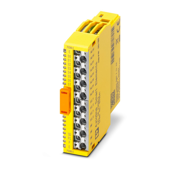
- Page 1 AXL SE PSDI8/3 Axioline Smart Element with safe digital inputs Original operating instructions...
- Page 2 UM EN AXL SE PSDI8/3, Revision 02 2021-01-20 This user manual is valid for: Designation Revision Order No. as of HW/FW AXL SE PSDI8/3 00/100 1079241 PHOENIX CONTACT GmbH & Co. KG • Flachsmarktstraße 8 • 32825 Blomberg • Germany phoenixcontact.com...
-
Page 3: Table Of Contents
Terminal point assignment................... 18 Local diagnostic and status indicators..............19 Safe state ......................21 3.8.1 Operating state ..................21 3.8.2 Error detection in I/O devices ............... 21 3.8.3 Device error ..................22 3.8.4 Parameterization errors ................ 22 3 / 84 PHOENIX CONTACT 108928_en_02... - Page 4 AXL SE PSDI8/3 Safety-related system time .................. 23 3.9.1 Processing time of the input in the event of a safety demand ....23 3.9.2 Error detection time ................23 3.9.3 Duration of a safety demand ..............23 3.9.4 Response time of the PROFIsafe system ..........24 3.10...
- Page 5 12.1 Ordering data ...................... 75 12.2 Technical data ..................... 76 12.2.1 Interface types according to ZVEI classification ........80 Appendix ..........................81 Diagnostic messages for parameter errors for PROFIsafe ........81 Revision history ........................82 5 / 84 PHOENIX CONTACT 108928_en_02...
-
Page 6: For Your Safety
AXL SE PSDI8/3 For your safety Read this user manual carefully and keep it for future reference. Identification of warning notes This symbol indicates hazards that could lead to personal injury. There are three signal words indicating the severity of a potential injury. -
Page 7: Field Of Application Of The Product
1.3.1 Intended use The AXL SE PSDI8/3 Smart Element is designed for use within a PROFIsafe system. To do so, the Smart Element is integrated in the Axioline F system via an Axioline F backplane. The Smart Element is designed for the connection of: –... -
Page 8: Safety Notes
AXL SE PSDI8/3 Safety notes Observe the country-specific installation, safety, and accident prevention regulations. NOTE: Electrostatic discharge Electrostatic discharge can damage or destroy components. When handling the device, observe the necessary safety precautions against electrostatic discharge (ESD) in accor- dance with EN 61340-5-1 and IEC 61340-5-1. -
Page 9: Ul Notes
OUT_T1 and OUT_T2) Power consumption 32 W, maximum (all inputs set, with supply to the sensors via clock supplies OUT_T1 and OUT_T2) Observe the complete section “Technical data and ordering data” on page 9 / 84 PHOENIX CONTACT 108928_en_02... -
Page 10: Applied Directives And Standards
UM EN AXL F SYS INST – Documentation for the backplane used – Documentation for the bus coupler used Safety hotline Should you have any technical questions, please contact Phoenix Contact. Subsidiary contact information is available at phoenixcontact.com. 10 / 84 PHOENIX CONTACT 108928_en_02... -
Page 11: Transport, Storage, And Unpacking
Read the complete packing slip carefully before unpacking the device. • Retain the packing slip. • Check the delivery for damage and completeness. Checking the delivery • Submit claims for any transport damage immediately. 11 / 84 PHOENIX CONTACT 108928_en_02... -
Page 12: Product Description
Product description Short description The AXL SE PSDI8/3 Smart Element is a safe input module in the Axioline SE product range for use in a PROFIsafe system. The Smart Element is suitable for use on an Axioline F backplane. The Smart Element is integrated in the Axioline F system via the Axioline F backplane. -
Page 13: Housing Dimensions
Product description Housing dimensions Figure 3-2 shows the dimensions of the Smart Elements. The dimensions are independent of the number of terminal points. 58,7 55,2 14,9 35,8 Figure 3-2 Housing dimensions (in mm) 13 / 84 PHOENIX CONTACT 108928_en_02... -
Page 14: Supply Voltages
AXL SE PSDI8/3 Supply voltages A Smart Element requires the following supply voltages: – Communications power U of the Smart Element – I/O supply voltage U The Smart Element receives both supply voltages via the Smart Element interface. Technical data ... -
Page 15: Safe Digital Inputs
The achievable safety integrity level (SIL, SILCL, Cat., PL) and error detection depends on the following: – Parameterization – Structure of the sensor – Cable installation “Parameterization of the safe inputs” on page “Connection examples of safe inputs” on page 15 / 84 PHOENIX CONTACT 108928_en_02... -
Page 16: Clock Outputs Out_T1 And Out_T2
AXL SE PSDI8/3 3.5.1 Clock outputs OUT_T1 and OUT_T2 The Smart Element has two independent clock outputs. The clock outputs supply the safe inputs. Both clock outputs provide a pulse pattern if cross-circuit monitoring has been acti- vated for at least one input pair. The pulse pattern is used to detect cross-circuits in the exter- nal wiring of the inputs. -
Page 17: Connection Options For Sensors
Achievable safety integrity SILCL Cat. For connection example, see page Cat. 3 can be achieved by linking two 1-channel sensors in the control logic. The category that can be achieved depends on the sensor used. 17 / 84 PHOENIX CONTACT 108928_en_02... -
Page 18: Terminal Point Assignment
AXL SE PSDI8/3 Terminal point assignment Starting from the top, the terminal points are marked with 0, 1, ... 15. Table 3-1 Terminal point assignment Figure Terminal point Signal Assignment IN0_CH1 Input 0, channel 1 IN0_CH2 Input 0, channel 2... -
Page 19: Local Diagnostic And Status Indicators
Green Diagnostics for safe communication protocol Green off No safe communication. Green on Safe communication is running without errors. Flashing green Safe communication is running.The PROFIsafe system is requesting an 1 Hz acknowledgment. 19 / 84 PHOENIX CONTACT 108928_en_02... - Page 20 AXL SE PSDI8/3 Table 3-2 Overview of diagnostic LEDs [...] Desig- Color State Description nation Error / diagnostics of module error No error. Flashing red Communication error. 4 Hz Check whether the Smart Element has been plugged in correctly. Red on I/O error.
-
Page 21: Safe State
The diagnostic message is transmitted to the controller. See “Errors: messages and removal” on page For information on which errors occur and when, please refer to the following section. See “Connection examples of safe inputs” on page 21 / 84 PHOENIX CONTACT 108928_en_02... -
Page 22: Device Error
AXL SE PSDI8/3 3.8.3 Device error Operating time in the error state WARNING: Loss of the safe state in the error state In the error state, internal module tests are no longer run. It is possible that the safe state may be exited due to an accumulation of errors. -
Page 23: Safety-Related System Time
The duration of a safety demand must be greater than the processing time of the corre- sponding input t If the Smart Element detects a safety demand after the processing time of input t elapsed, the Smart Element extends the demand until the controller has received the demand. 23 / 84 PHOENIX CONTACT 108928_en_02... -
Page 24: Response Time Of The Profisafe System
Programming data/configuration data The device is described in the device description files. The device descriptions for controllers from Phoenix Contact are included in PC Worx and PLCnext Engineer, as well as in the corresponding service packs. The device description files for other systems are available for download at phoenixcon- tact.net/products... -
Page 25: Mounting And Removal
Wall mounting on a horizontal DIN rail on the wall is the preferred mounting position. This mounting position provides optimum air flow for the Smart Elements. Securing the control In order to prevent tampering, secure the control cabinet or control box against being cabinet opened by unauthorized persons. 25 / 84 PHOENIX CONTACT 108928_en_02... -
Page 26: Setting The Safety Address
AXL SE PSDI8/3 Setting the safety address 4.2.1 Address assignment via DIP switch Setting the address prior A 10-pos. DIP switch is located on the side of the Smart Element. to mounting The DIP switch is used to set the PROFIsafe address (F-Address). -
Page 27: Mounting The Smart Element
To remove the Smart Element from its slot, pull the release mechanism vertically upwards (A). • Pull the Smart Element out of its slot (B). Figure 4-3 Removing the Smart Element from its slot 27 / 84 PHOENIX CONTACT 108928_en_02... -
Page 28: Optional Equipment Identification
AXL SE PSDI8/3 Optional equipment identification You can apply an equipment ID to the Smart Element. Two options are available: Stick a label to the release mechanism. Snap a marker onto the release mechanism. Position for equipment identifica- tion Adhesive label... -
Page 29: Electrical Installation
When selecting the equipment, please take into consideration the dirt and overvoltages which may occur during operation. • If you expect overvoltages in the system, which exceed the values defined in overvolt- age category II, take into consideration additional measures for voltage limitation. 29 / 84 PHOENIX CONTACT 108928_en_02... -
Page 30: Cables Connected To Smart Elements
AXL SE PSDI8/3 Cables connected to Smart Elements All electrical connections of the Smart Element have Push-in technology. The cables for the I/O devices are directly connected to the Smart Element. • Observe the maximum current carrying capacity of the connections. -
Page 31: Conductor Cross Sections, And Stripping And Insertion Lengths
• Crimp the ferrules in a trapezoidal way. Recommended tool: Crimping tool for trapezoidal crimp – CRIMPFOX 6 – CRIMPFOX DUO 10 – CRIMPFOX 10T-F “Accessories” on page 31 / 84 PHOENIX CONTACT 108928_en_02... - Page 32 AXL SE PSDI8/3 Ferrules A selection of appropriate ferrules can be found in the UM EN AXL SE SYS INST user manual or on the Internet at phoenixcontact.net/products. TWIN ferrules When using TWIN ferrules, please observe the following: Tabelle 5-4...
-
Page 33: Terminal Points And Associated Spring Lever
Terminal point with associated spring lever, and associated touch connection Terminal point Associated spring lever Touch connection A selection of appropriate test pins can be found in the UM EN AXL SE SYS INST user manual or on the Internet at phoenixcontact.net/products. 33 / 84 PHOENIX CONTACT 108928_en_02... -
Page 34: Connecting The Cables
AXL SE PSDI8/3 Connecting the cables Wire the Smart Element according to your application. When wiring, proceed as follows: • Strip 8 mm off the cable. Without tools Suitable for: – Conductor cross sections from 0.5 mm² onwards – Solid cables –... - Page 35 • Open the spring by pressing on the spring lever (A) using a screwdriver. Use a bladed screwdriver with a blade width of 2.5 mm, for example. Phoenix Contact recommends the SZS 0,4x2,5 screwdriver. See “Accessories” on page •...
-
Page 36: Removing Cables From The Terminal Point
This opens the leg-spring connection of the relevant terminal point (A). A suitable tool is, for example, a bladed screwdriver with a blade width of 2.5 mm. Phoenix Contact recommends the SZS 0,4x2,5 screwdriver. See “Accessories” on page •... -
Page 37: Parameterization
FS LED indicates that the parameterization is invalid. In addition, the error is reported to the controller. In this case, check and correct the settings. See “Errors: messages and removal” on page F-Parameters and Assign the parameterizable F-Parameters and i-Parameters. i-Parameters 37 / 84 PHOENIX CONTACT 108928_en_02... -
Page 38: Parameterization Of The Safe Inputs
AXL SE PSDI8/3 Parameterization of the safe inputs The individual input pairs of a Smart Element can be parameterized differently, which means that different safety integrity levels (SIL, SILCL, Cat., PL) can be achieved. The safe inputs are parameterized in pairs. -
Page 39: Single-Channel Assignment
When switching on the sensor again please note the following: a delayed change in state at one of the two inputs can result in delayed transmission of state “1” in the process data image of the inputs. 39 / 84 PHOENIX CONTACT 108928_en_02... - Page 40 AXL SE PSDI8/3 State evaluation The Smart Element evaluates the states of the inputs and transmits the result to the control- ler. The following values are transmitted in the process data image of the safe inputs: – “0” if a “0” signal is present at at least one of the two inputs or an error has been detected –...
-
Page 41: Two-Channel Non-Equivalent Assignment
Example of correct and incorrect signal change IN0_C 1 IN0_C 2 IN0 (C 1/C 2) Figure 6-3 Correct signal change IN0_C 1 IN0_C 2 IN0 (C 1/C 2) Figure 6-4 Error during signal change 41 / 84 PHOENIX CONTACT 108928_en_02... -
Page 42: Symmetry And Start Inhibit
AXL SE PSDI8/3 Key: IN0_CH1 Signal sequence at input 0, channel 1 IN0_CH2 Signal sequence at input 0, channel 2 IN0 (CH1/CH2) Safety-related signal for 2-channel input 0, channel 1, and channel 2 at the controller Figure 6-4, the following condition has not been met: both signals must be in the opposite state before the state is changed. - Page 43 IN0_C 1 IN0_C 2 Diag Figure 6-7 Example of a signal change outside the parameterized time for symmetry monitoring, start inhibit due to symmetry violation is enabled 43 / 84 PHOENIX CONTACT 108928_en_02...
-
Page 44: Cross-Circuit Detection
AXL SE PSDI8/3 Acknowledging the diagnostic message After acknowledging the diagnostic message, the current state at the input is immediately transmitted to the controller. If required, implement a startup inhibit in the application program following error acknowl- edgment. For examples and further information on error detection and error messages, please refer to the following sections: –... -
Page 45: Connection Examples Of Safe Inputs
Observe the requirements of the standards with regard to the external wiring and the sen- sensor sors to be used to achieve the desired safety integrity level. Observe the technical data of the safe inputs when selecting the sensor. See “Safe digital inputs” on page 45 / 84 PHOENIX CONTACT 108928_en_02... -
Page 46: Single-Channel Assignment Of Safe Inputs
AXL SE PSDI8/3 Single-channel assignment of safe inputs 7.2.1 Cross-circuit monitoring enabled, supply through assigned clock output Safety switch IN _C 1 OUT_T1 Figure 7-1 1-channel assignment of the inputs Basic specifications Sensor 1-channel Sensor supply Internally through assigned clock output (clocked) Achievable SIL 2/SILCL 2/Cat. - Page 47 Clock output to ground Short cir- The error is detected as a short circuit of the clock output. cuit The affected clock output is disabled. SF = safety function 47 / 84 PHOENIX CONTACT 108928_en_02...
-
Page 48: Cross-Circuit Monitoring Disabled, Supply Through A Clock Output Or External 24 V
AXL SE PSDI8/3 7.2.2 Cross-circuit monitoring disabled, supply through a clock output or external 24 V Safety switch OUT_T1(T2) Supply through OUT_T1 or IN _C 1 OUT_T2 OUT_ (T2) Figure 7-2 1-channel assignment of inputs: supply through OUT_T1(T2) Safety switch... - Page 49 The error is only detected as a change in state from “1” to “0” in state “1” of the input. An unexpected change from “0” to “1” is possible. Make sure that this change in state cannot restart the sys- tem unintentionally. SF = safety function 49 / 84 PHOENIX CONTACT 108928_en_02...
-
Page 50: Supply Through Ossd
AXL SE PSDI8/3 7.2.3 Supply through OSSD OSSD OSSD sensor OSSD +24 V IN _C 1 Figure 7-4 1-channel assignment of inputs: external supply (OSSD) WARNING: Loss of the safety function Parasitic voltages can result in the loss of the safety function. - Page 51 The error is only detected as a change in state from “1” to “0” in state “1” of the input. An unexpected change from “0” to “1” is possible. Make sure that this change in state cannot restart the sys- tem unintentionally. SF = safety function 51 / 84 PHOENIX CONTACT 108928_en_02...
-
Page 52: Two-Channel Equivalent Assignment Of The Safe Inputs
AXL SE PSDI8/3 Two-channel equivalent assignment of the safe inputs 7.3.1 Cross-circuit monitoring enabled, supply through OUT_T1 and OUT_T2 S1, S2 Switching elements IN _C 1 OUT_T1, Supply through OUT_T1 and OUT_T2 OUT_T2 OUT_T1 IN _C 2 OUT_T2 Figure 7-5... - Page 53 “0”. Input to non-assigned clock Cross-cir- “Cross-circuit detection” on page output cuit Clock output to clock output Cross-cir- The error is detected for inputs which are assigned to dif- cuit ferent clock outputs. 53 / 84 PHOENIX CONTACT 108928_en_02...
- Page 54 AXL SE PSDI8/3 Table 7-4 2-channel equivalent with cross-circuit monitoring: supply through OUT_T1 and OUT_T2 [...] Error type Detec- Diagnos- Loss of Comment tion tics Short circuit Input to ground Symme- The error is detected in state “1” or on a change in state try viola- from “0”...
-
Page 55: Cross-Circuit Monitoring Disabled, Supply Through A Clock Output Or External Supply
Input xx, channel 1/channel 2 Assignment Used, 2-channel equivalent Mandatory setting Filter time (t 3 ms Application-specific Filter Symmetry 100 ms Application-specific Start inhibit due to symmetry Disabled Application-specific violation Cross-circuit monitoring Mandatory setting Disabled 55 / 84 PHOENIX CONTACT 108928_en_02... - Page 56 AXL SE PSDI8/3 Device diagnostics and behavior of the Smart Element in the event of an error Observe the information to understand the change in state: see “Example of correct and incorrect signal change” on page Table 7-5 2-channel equivalent, cross-circuit monitoring disabled: supply through a clock output or external supply...
- Page 57 WARNING: Loss of the safety function An accumulation of errors can result in the loss of the safety function. • Test the safety function at regular intervals to detect errors at an early stage. 57 / 84 PHOENIX CONTACT 108928_en_02...
-
Page 58: External Supply (Ossd)
AXL SE PSDI8/3 7.3.3 External supply (OSSD) OSSD +24 V IN _C 1 IN _C 2 Figure 7-8 2-channel equivalent assignment of the inputs, external supply (OSSD) WARNING: Loss of the safety function Parasitic voltages can result in the loss of the safety function. - Page 59 GND) Cross-circuit Input to input None The error must be detected by the sensor. The sensor must ensure that the safe state is entered in the event of an error. 59 / 84 PHOENIX CONTACT 108928_en_02...
- Page 60 AXL SE PSDI8/3 Table 7-6 2-channel equivalent: external supply (OSSD) [...] Error type Detec- Diagnos- Loss of Comment tion tics Input to clock output Symme- – In state “0”: try viola- The safe input detects symmetry violation, as state “1”...
-
Page 61: Two-Channel Non-Equivalent Assignment Of The Safe Inputs
Input xx, channel 1/channel 2 Assignment Used, 2-channel non-equivalent Mandatory setting Filter time (t 3 ms Application-specific Filter Symmetry 100 ms Application-specific Start inhibit due to symmetry Disabled Application-specific violation Cross-circuit monitoring Enabled Mandatory setting 61 / 84 PHOENIX CONTACT 108928_en_02... - Page 62 AXL SE PSDI8/3 Device diagnostics and behavior of the Smart Element in the event of an error Observe the information to understand the change in state: see “Example of correct and incorrect signal change” on page Table 7-7 2-channel non-equivalent with cross-circuit monitoring: supply through OUT_T1 and OUT_T2...
-
Page 63: Cross-Circuit Monitoring Disabled, Supply Through A Clock Output Or External Supply
Input xx, channel 1/channel 2 Assignment Mandatory setting Used, 2-channel non-equivalent Filter time (t 3 ms Application-specific Filter Symmetry 100 ms Application-specific Start inhibit due to symmetry Enabled Application-specific violation Cross-circuit monitoring Disabled Mandatory setting 63 / 84 PHOENIX CONTACT 108928_en_02... - Page 64 AXL SE PSDI8/3 Device diagnostics and behavior of the Smart Element in the event of an error Observe the information to understand the change in state: see “Example of correct and incorrect signal change” on page Table 7-8 2-channel non-equivalent without cross-circuit monitoring: supply through a clock output or external supply...
- Page 65 Test the safety function at regular intervals to detect errors at an early stage. An error in input circuit INx_CH2 can only be detected in the event of a demand of the safety function. 65 / 84 PHOENIX CONTACT 108928_en_02...
-
Page 66: Startup And Validation
AXL SE PSDI8/3 Startup and validation Initial startup Qualified personnel Startup may only be carried out by qualified personnel. Steps for startup To start up the Smart Element, proceed as follows: Set the safety address. See “Setting the safety address” on page Mount the Smart Element on the backplane. -
Page 67: Errors: Messages And Removal
Error location 255 (0xFF) means that the entire Smart Element is affected. Example: In the event of a short circuit at terminal point 5 of input IN2_CH2, value 0x05 is indicated in the function block. 67 / 84 PHOENIX CONTACT 108928_en_02... -
Page 68: Error Codes
AXL SE PSDI8/3 Error codes If error codes are indicated by the system but do not appear in the table, please contact Phoenix Contact. Table 9-2 Error codes Error code Error cause Description/effect Remedy/acknowledgment (+ AddValue) [hex] 0000 No errors have occurred. - Page 69 Check the DIP switch settings. yellow on during operation during operation has been • Carry out a power-up. detected. The Smart Element This diagnostic message cannot be switches to the safe state. red on acknowledged. 69 / 84 PHOENIX CONTACT 108928_en_02...
- Page 70 AXL SE PSDI8/3 Error code Error cause Description/effect Remedy/acknowledgment (+ AddValue) [hex] 6320 Symmetry monitoring Correct the parameterization: has been enabled – Disable symmetry monitoring. + 034X and the input pairs – Or parameterize input pairs as 2- are parameterized as channel.
- Page 71 The If an error message is output again, Smart Element is not Smart Element switches to the the Smart Element is defective and ready safe state. red on must be replaced. 71 / 84 PHOENIX CONTACT 108928_en_02...
-
Page 72: Profisafe Errors
AXL SE PSDI8/3 PROFIsafe errors The following errors can also occur: – PROFIsafe system errors See “Diagnostic messages for parameter errors for PROFIsafe” on page – PROFIBUS or PROFINET system errors. For information on these errors, refer to the documentation for the system used. -
Page 73: 10 Device Replacement, Device Defect, And Repair
Device defect and repair Do not open the housing Repairs may only be carried out by Phoenix Contact. Do not open the housing. If the housing is opened, the function of the device can no longer be ensured. Defective devices Please contact Phoenix Contact. -
Page 74: 11 Maintenance, Decommissioning, And Disposal
AXL SE PSDI8/3 11 Maintenance, decommissioning, and disposal 11.1 Maintenance The Smart Element requires no maintenance during the permissible duration of use. For the duration of use, please refer to the technical data. See “Technical data and ordering data” on page Depending on the application and connected I/O devices, the function of the I/O devices and the safety chain must be tested regularly. -
Page 75: 12 Technical Data And Ordering Data
12.1 Ordering data Description Type Order No. Pcs./Pkt. Axioline Smart Elements, digital input module, safe digital AXL SE PSDI8/3 1079241 inputs: 8 (1-channel assignment), 4 (2-channel assign- ment), 24 V DC, connection method: 3-wire, degree of protection: IP20 Accessories Type Order No. -
Page 76: Technical Data
AXL SE PSDI8/3 12.2 Technical data Dimensions (nominal sizes in mm) Width 14.9 mm Height 62.2 mm Depth 62 mm General data Color Zinc yellow, RAL 1018 Weight 36 g Operating mode PROFIsafe 2.4, PROFIsafe 2.6.1 Ambient temperature (operation) -25 °C ... 60 °C Ambient temperature (storage/transport) -40 °C …... - Page 77 11 V DC ... 30 V DC Input current range for “0” signal 1.5 mA, maximum Input current range for “1” signal Minimum 2 mA Input filter time 1.5 ms, 3 ms (default), 5 ms, 15 ms 77 / 84 PHOENIX CONTACT 108928_en_02...
- Page 78 AXL SE PSDI8/3 Safe digital inputs Cable length 200 m, maximum (from clock output to the safe input (total based on forward and return path)) Switching frequency 10 Hz, maximum Protection against polarity reversal of the inputs Diode Clock outputs...
- Page 79 Safety characteristic data for EN 62061 SILCL 2 (1-channel assignment) 3 (2-channel assignment) 1.00 x 10 , maximum (1-channel assignment) 1.00 x 10 , maximum (2-channel assignment) Approvals For the latest approvals, please visit phoenixcontact.net/products. 79 / 84 PHOENIX CONTACT 108928_en_02...
-
Page 80: Interface Types According To Zvei Classification
AXL SE PSDI8/3 12.2.1 Interface types according to ZVEI classification Source/ Interface type Additional Source/ Suitable Suitable Suitable Suitable drain measure drain interface interface interface interface type type type type Drain Source Interface type A - drain Parameter Minimum Typical (24 V) -
Page 81: A Appendix
Correct the value. Non-specified (unknown) error Table A-2 i-Parameter parameter errors AddValue Error cause Remedy (hex) 03F2 iPar_CRC is incorrect. Check the i-Parameters. Repeat the calcula- tion. 03FB PST_Device_ID is incorrect. Contact Phoenix Contact. 81 / 84 PHOENIX CONTACT 108928_en_02... -
Page 82: B Revision History
AXL SE PSDI8/3 B Revision history Revision Date Content Page 2020-02-04 First publication 2020-09-11 Correction of the terminal points in Table 3-1 „Terminal point assignment“ 2021-01-20 Section „UL notes“ inserted Section „Process data words“ inserted Section „Conductor cross sections, and stripping and insertion lengths“... - Page 83 The receipt of technical documentation (in particular user documentation) does not constitute any further duty on the part of Phoenix Contact to furnish information on modifications to products and/or technical documentation. You are responsible to verify the suitability and intended use of the products in your specific application, in particular with regard to observing the applicable standards and regulations.
- Page 84 Should you have any suggestions or recommendations for improvement of the contents and layout of our manuals, please send your comments to: tecdoc@phoenixcontact.com 84 / 84 PHOENIX CONTACT GmbH & Co. KG • Flachsmarktstraße 8 • 32825 Blomberg • Germany phoenixcontact.com...
Need help?
Do you have a question about the AXL SE PSDI8/3 and is the answer not in the manual?
Questions and answers