Table of Contents
Advertisement
Quick Links
Power Supply, Primary Switch Mode
for Universal Use
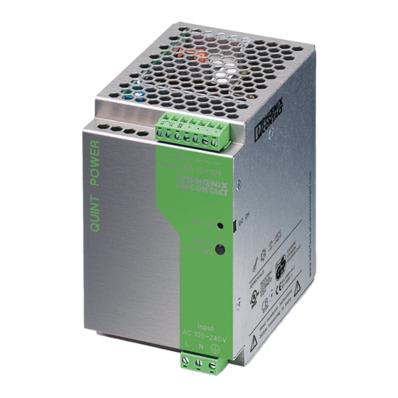
QUINT-PS-100-240AC/12DC/10
QUINT POWER provides:
• Preventive function monitoring through
professional signaling
• Global use due to a wide range input
• A high level of operational safety even in complex
global networks
• Reliable startup of heavy loads due to POWER
BOOST
The reliability of a power supply determines the
availability of individual components in a system and
whether complex systems can function safely.
The globalization of markets increases the demands
placed on the power supply. A wide range input and a
high level of availability are required.
These requirements are met by Generation 2
QUINT POWER.
1. Short Description
The QUINT POWER product range offers universal
DC power supplies from 60 - 960 W. Depending on the
type, regulated and adjustable output voltages of
12 V DC, 24 V DC or 48 V DC are available for output
currents of 2.5 A, 5 A, 10 A, 20 A, 30 A, and 40 A.
These devices, which are designed as primary
switched-mode regulators, operate with a high level of
efficiency so that the heat loss is kept to a minimum.
The high level of operational safety is also ensured in
complex global networks. QUINT POWER also
operates in applications where static voltage dips,
transient power supply failures or phase failure are
common.
Large capacitors ensure mains buffering of more
than 20 ms at full load. All 3-phase QUINT POWER
units provide the complete output power even in the
event of a continuous phase failure.
Reliable startup of heavy loads is ensured by a
power reserve of up to 50% - the POWER BOOST.
Preventive function monitoring diagnoses an
impermissible operating state and minimizes
downtimes in your system. An active transistor output
and an electrically isolated relay contact are provided
for remote monitoring of this state.
This signal not only provides information on the
device function, but also indicates a system overload at
an early stage.
Headquarters: © Phoenix Contact GmbH & Co. KG • Flachsmarktstraße 8 • 32825 Blomberg • Germany
Phone +49 - 52 35 - 30 0 • Fax +49 - 52 35 - 34 12 00 • www.phoenixcontact.com
Local Contact: www.phoenixcontact.com/salesnetwork
2. Area of Application
QUINT POWER can be used globally due to the
consistent provision of a wide range input.
In this way, your entire system can be tested at any
production location in the world and can be delivered to
any location in the world without faulty switching of the
input voltage. This reduces storage costs and logistical
effort.
An international approval package including CB
Scheme, UL 60950 for IT equipment, and UL 508 for
industrial control equipment enables the device to be
used globally.
Safe operation in adverse conditions is emphasized
by the approval of all QUINT POWER units with 24 V
output voltage by Germanischer Lloyd.
Advertisement
Table of Contents

Subscribe to Our Youtube Channel
Related Manuals for Phoenix Contact QUINT-PS-100-240AC/12DC/10


Summary of Contents for Phoenix Contact QUINT-PS-100-240AC/12DC/10
- Page 1 Headquarters: © Phoenix Contact GmbH & Co. KG • Flachsmarktstraße 8 • 32825 Blomberg • Germany Phone +49 - 52 35 - 30 0 • Fax +49 - 52 35 - 34 12 00 • www.phoenixcontact.com...
-
Page 2: Solid 2 ]
40 mA, maximum DC OK (electrically isolated) 4 30 V AC/DC, maximum; 1 A, maximum = contact closed) > 0.9 x U = LED flashing) LED 6 (U < 0.9 x U Green LED PHOENIX CONTACT page 2 of 10... -
Page 3: Input
Criterion A: Normal operating characteristics within the specified asymmetrical: Cable to ground limits. Criterion B: Temporary adverse effects on the operating Class A: Industrial application characteristics that the device corrects independently. Class B: Industrial and domestic applications PHOENIX CONTACT page 3 of 10... - Page 4 To ensure that the device can be operated safely and all functions can be used, please read these instructions carefully. Caution: Never carry out work when the power is turned on, this is highly dangerous. PHOENIX CONTACT page 4 of 10...
- Page 5 Installation depth 88 mm (3.465 in.) (+ DIN rail) (+ DIN rail) 85 mm (3.346 in.) 122 mm (4.803 in.) + + – – 13 14 Output DC 12V 10A DC OK Adjust 11.5-18V Input AC 100-240V Figure 06 PHOENIX CONTACT page 5 of 10...
- Page 6 To do this, mount the DIN rail adapter (UTA 107) 7 7 7 7 as shown in Figure 08. No additional mounting material is required. Mounting screws: Torx T10 (torque 0.8 - 0.9 Nm/7 - 8 Ib in.). Figure 07 Figure 08 PHOENIX CONTACT page 6 of 10...
-
Page 7: Table Of Contents
Note that an all-pole disconnecting device must be provided for two-phase operation using two external conductors for a three-phase network. For example, primary side line protection could be used. PHOENIX CONTACT page 7 of 10... - Page 8 The DC OK signal is isolated from the power output. This ensures that a separate supply does not enter from devices connected in parallel. The 12 V DC signal can be connected directly to a logic input for evaluation. Figure 13 PHOENIX CONTACT page 8 of 10...
- Page 9 The output power is decreased so low that device protection is provided. Once the device has cooled, the output power is increased again. Ambient temperature [°C] Figure 16 PHOENIX CONTACT page 9 of 10...
- Page 10 Otherwise, the loads should be divided over independent individual devices. A maximum of five devices can be connected in parallel. PHOENIX CONTACT page 10 of 10...
Need help?
Do you have a question about the QUINT-PS-100-240AC/12DC/10 and is the answer not in the manual?
Questions and answers