Table of Contents
Advertisement
QUINT4-PS/1AC/24DC/40
Power supply unit
Data sheet
108827_en_01
1
Description
QUINT POWER power supplies with SFB Technology and
preventive function monitoring ensure superior system
availability.
Powerful
–
SFB Technology: 6 times the nominal current for 15 ms
–
Power reserves:
Static boost of up to 125% (P
Dynamic boost of up to 200% (P
Robust
–
Mains buffering ≥ 20 ms
–
High degree of electrical immunity, thanks to integrated
gas discharge tube (6 kV)
Preventive
–
Comprehensive signaling:
Analog signal, digital signal, relay contact, LED bar
graph
Can be ordered pre-configured
–
Perform configuration online and order 1 or more units
Long service life
–
Well over 15 years
All technical specifications are nominal values and refer to a room temperature of 25 °C and 70 % relative
humidity at 100 m above sea level.
© PHOENIX CONTACT
) for a sustained period
N
) for 5 s
N
2020-05-14
Technical data (short form)
Input voltage range
Mains buffering
Nominal output voltage (U
)
N
Setting range of the output voltage
(U
)
Set
Nominal output current (I
)
N
Static Boost (I
)
Stat.Boost
Dynamic Boost (I
)
Dyn.Boost
Selective Fuse Breaking (I
)
SFB
Output power (P
)
N
Output power (P
)
Stat. Boost
Output power (P
)
Dyn. Boost
Efficiency
Residual ripple
MTBF (IEC 61709, SN 29500)
Ambient temperature (operation)
Dimensions W/H/D
Weight
100 V AC ... 240 V AC
-15 % ... +10 %
typ. 29 ms (120 V AC)
typ. 32 ms (230 V AC)
24 V DC
24 V DC ... 29.5 V DC
40 A
45 A
60 A (5 s)
215 A (15 ms)
960 W
1080 W
1440 W
typ. 94.8 % (120 V AC)
typ. 95.9 % (230 V AC)
< 50 mV
PP
> 555000 h (40 °C)
-25 °C ... 70 °C
-40°C (startup type tested)
> 60 °C Derating: 2.5 %/K
120 mm / 130 mm / 140 mm
2.6 kg
Advertisement
Table of Contents

Related Manuals for Phoenix Contact QUINT4-PS/1AC/24DC/40


Summary of Contents for Phoenix Contact QUINT4-PS/1AC/24DC/40
-
Page 1: Description
QUINT4-PS/1AC/24DC/40 Power supply unit Data sheet 108827_en_01 © PHOENIX CONTACT 2020-05-14 Description QUINT POWER power supplies with SFB Technology and preventive function monitoring ensure superior system Technical data (short form) availability. Input voltage range 100 V AC ... 240 V AC -15 % ... +10 %... -
Page 2: Table Of Contents
QUINT4-PS/1AC/24DC/40 Table of contents Description ..........................1 Table of contents ........................2 Ordering data .......................... 3 Technical data ......................... 5 Safety and installation notes ....................16 High-voltage test (HIPOT) ..................... 18 Structure of the power supply ....................20 Mounting/removing the power supply ..................23 Device connection terminal blocks .................. -
Page 3: Ordering Data
Near Field Communication (NFC) programming adapter TWN4 MIFARE NFC USB 2909681 with USB interface for the wireless configuration of NFC- ADAPTER capable products from PHOENIX CONTACT with software. No separate USB driver is required. Type 2/3 surge protection, consisting of protective plug PLT-SEC-T3-230-FM-UT 2907919 and base element with screw connection. - Page 4 QUINT4-PS/1AC/24DC/40 Accessories Type Order No. Pcs./Pkt. Electronic device circuit breaker, number of positions: 1, CBMC E4 24DC/1-4A NO 2906031 mounting type: DIN rail: 35 mm, Color: light grey RAL 7035 Electronic device circuit breaker, number of positions: 1, CBMC E4 24DC/1-10A NO 2906032 mounting type: DIN rail: 35 mm, Color: light grey RAL 7035...
-
Page 5: Technical Data
QUINT4-PS/1AC/24DC/40 Technical data Input data Unless otherwise stated, all data applies for 25°C ambient temperature, 230 V AC input voltage, and nominal output current (I Input voltage range 100 V AC ... 240 V AC -15 % ... +10 % 110 V DC ... 250 V DC -18 % ... +40 % Electric strength, max. - Page 6 QUINT4-PS/1AC/24DC/40 Input protection , AC/DC ( to be connected externally upstream ) Input current I Neozed fuse Circuit breaker Power switch Input protection or equivalent ≤ 13 x I Characteristics (maximum magnetic tripping) ...
- Page 7 QUINT4-PS/1AC/24DC/40 Crest factor 120 V AC 230 V AC typ. 1.5 typ. 1,6 Input current vs. output current 14,0 12,0 10,0 : 120 V AC/U : 24 V DC : 230 V AC/U : 24 V DC Input connection data...
- Page 8 QUINT4-PS/1AC/24DC/40 Output connection data Connection method Screw connection Conductor cross section, solid 0.5 mm² ... 16 mm² Conductor cross section, flexible 0.5 mm² ... 16 mm² Conductor cross section flexible, with ferrule with plastic 0.5 mm² ... 16 mm² sleeve Conductor cross section flexible, with ferrule without 0.5 mm²...
- Page 9 QUINT4-PS/1AC/24DC/40 Signal connection data Connection method Push-in connection Conductor cross section, solid 0.2 mm² ... 1 mm² Conductor cross section, flexible 0.2 mm² ... 1.5 mm² Conductor cross section flexible, with ferrule with plastic 0.2 mm² ... 0.75 mm² sleeve Conductor cross section flexible, with ferrule without 0.2 mm²...
- Page 10 QUINT4-PS/1AC/24DC/40 Efficiency 120 V AC 230 V AC typ. 94.8 % typ. 95.9 % : 120 V AC/U : 24 V DC : 230 V AC/U : 24 V DC Ambient conditions Ambient temperature (operation) -25 °C ... 70 °C (> 60 °C Derating: 2.5 %/K) The ambient temperature (operation) refers to UL 508 surrounding air temperature.
- Page 11 QUINT4-PS/1AC/24DC/40 Standards Safety transformers for power supply units EN 61558-2-16 Electrical safety (of information technology equipment) IEC 60950-1/VDE 0805 (SELV) Electrical safety (of control and regulation devices) IEC 61010-1 SELV IEC 60950-1 (SELV) EN 60204-1 (PELV) Limitation of mains harmonic currents EN 61000-3-2 Network version/undervoltage SEMI F47-0706;...
- Page 12 QUINT4-PS/1AC/24DC/40 Electromagnetic compatibility Noise emission according to EN 61000-6-3 (residential and commercial) and EN 61000-6-4 (industrial) CE basic standard Minimum normative Higher requirements in requirements practice (covered) Conducted noise emission EN 55016 EN 61000-6-4 (Class A) EN 61000-6-3 (Class B) Noise emission EN 55016 EN 61000-6-4 (Class A)
- Page 13 QUINT4-PS/1AC/24DC/40 Immunity according to EN 61000-6-1 (residential), EN 61000-6-2 (industrial), and EN 61000-6-5 (power station equipment zone), IEC/EN 61850-3 (energy supply) CE basic standard Minimum normative Higher requirements in requirements of EN 61000- practice (covered) 6-2 (CE) (immunity for industrial environments) Surge voltage load (surge) EN 61000-4-5...
- Page 14 QUINT4-PS/1AC/24DC/40 Additional basic standard EN 61000-6-5 (immunity in power station), IEC/EN 61850-3 (energy supply) Basic standard Minimum normative Higher requirements in requirements of EN 61000- practice (covered) Pulse-shape magnetic field EN 61000-4-9 not required 1000 A/m Comments none Criterion A Damped oscillating magnetic field EN 61000-4-10...
- Page 15 QUINT4-PS/1AC/24DC/40 Criterion A Normal operating behavior within the specified limits. Criterion B Temporary impairment to operational behavior that is corrected by the device itself. Criterion C Temporary adverse effects on the operating behavior, which the device corrects automatically or which can be restored by actuating the operating elements.
-
Page 16: Safety And Installation Notes
QUINT4-PS/1AC/24DC/40 Safety and installation notes Symbols used Instructions and possible hazards are indicated by corresponding symbols in this document. This is the safety alert symbol. It is used to alert you to potential personal injury hazards. Obey all safety measures that follow this symbol to avoid possible personal injuries. - Page 17 QUINT4-PS/1AC/24DC/40 Safety and warning notes – The power supply is approved for the connection to TN, TT and IT power grids (star networks) with a maximum phase-to-phase voltage of 240 V AC WARNING: Danger to life by electric – If the device is connected to the IT system, a two-pos.
-
Page 18: High-Voltage Test (Hipot)
QUINT4-PS/1AC/24DC/40 High-voltage test (HIPOT) High-voltage dielectric test performed by the customer This protection class I power supply is subject to the Low Apart from routine and type tests to guarantee electrical Voltage Directive and is factory tested. During the HIPOT... - Page 19 QUINT4-PS/1AC/24DC/40 6.3.1 Performing high-voltage testing 6.3.2 Disconnecting the gas discharge tube If high-voltage testing of the control cabinet or the power The built-in gas discharge tube inside the device ensures supply as a stand-alone component is planned during final that the power supply is effectively protected against inspection and testing, the following features must be asymmetrical disturbance variables (e.g., EN 61000-4-5).
-
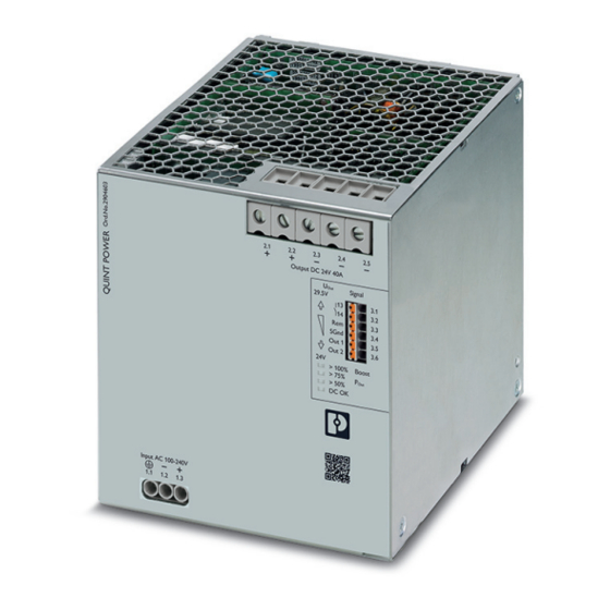
Page 20: Structure Of The Power Supply
QUINT4-PS/1AC/24DC/40 Structure of the power supply Device dimensions The fanless convection-cooled power supply can be snapped onto all DIN rails according to EN 60715. Function elements Output DC 24V 40A Signal 29,5V SGnd Out 1 Out 2 > 100% Boost > 75% >... - Page 21 QUINT4-PS/1AC/24DC/40 Keep-out areas Nominal output Spacing [mm] capacity < 50 % ≥ 50 % If adjacent components are active and the nominal output power ≥ 50%, there must be lateral spacing of 15 mm. Output DC 24V 40A Signal 29,5V...
- Page 22 QUINT4-PS/1AC/24DC/40 Block diagram active SGnd Out 1 Out 2 Figure 7 Block diagram Symbol Designation Symbol Designation Surge protection (gas discharge tube) Optocoupler (electrically isolating) Surge protection (varistor) with filter Additional regulatory protection against surge voltage Bridge rectifier Relay contact and signal contacts...
-
Page 23: Mounting/Removing The Power Supply
QUINT4-PS/1AC/24DC/40 Mounting/removing the power supply Mounting the power supply unit Proceed as follows to mount the power supply: In the normal mounting position the power supply is mounted on the DIN rail from above. Make sure that the universal DIN rail adapter is in the correct position behind the DIN rail (A). - Page 24 QUINT4-PS/1AC/24DC/40 8.3.2 Mounting the universal DIN rail adapter 8.4.1 Mounting the UWA 182/52 universal wall adapter To mount the universal DIN rail adapter on the left side of the device, proceed as follows: Proceed as follows to disassemble the universal DIN rail...
- Page 25 QUINT4-PS/1AC/24DC/40 8.4.2 Mounting the UWA 130 2-piece universal wall Fix connection wiring to the power supply adapter Two receptacles for the bundled attachment of the Proceed as follows to disassemble the universal DIN rail connection wiring are integrated in the left and right housing adapter that comes pre-mounted: panel.
-
Page 26: Device Connection Terminal Blocks
QUINT4-PS/1AC/24DC/40 Device connection terminal blocks – Shorten the excess length of the cable ties. – Then check again that the connection wiring is properly The AC input and DC output terminal blocks on the front of secured. the power supply feature screw connection technology. The signal level is wired without tools by means of Push-in connection technology. - Page 27 QUINT4-PS/1AC/24DC/40 Protection of the primary side Output Installation of the device must correspond to EN 60950-1 By default, the power supply is pre-set to a nominal output regulations. It must be possible to switch off the device using voltage of 24 V DC.
-
Page 28: Output Characteristic Curves
QUINT4-PS/1AC/24DC/40 Output characteristic curves This section describes the various output characteristic curves together with their areas of application for customization to your specific application. The U/I Advanced characteristic curve is set by default. Keeps temperatures Loads with high inrush Selective tripping of... - Page 29 QUINT4-PS/1AC/24DC/40 10.1 U/I Advanced output characteristic curve 10.2 Smart HICCUP output characteristic curve The preset U/I Advanced output characteristic curve is The SMART HICCUP output characteristic curve keeps the optimized for the following applications: thermal load of the connecting cables at a low level in the event of a sustained overload.
- Page 30 QUINT4-PS/1AC/24DC/40 10.3 FUSE MODE output characteristic curve In the event of an overload (e.g., short circuit), the power supply switches off the DC output permanently. The value of the switch-off threshold and the time period for which it may be exceeded can be freely selected. The power supply is restarted via the remote contact.
-
Page 31: Configuring The Power Supply
QUINT4-PS/1AC/24DC/40 Configuring the power supply 11.2 Configuring the power supply To configure the power supply, proceed as follows: With the fourth generation of the QUINT POWER power – Before you can configure the power supply, it should supply, it is now possible for the first time to adapt the either be disconnected from the supply voltage or behavior of the power supply. -
Page 32: Boost Currents
QUINT4-PS/1AC/24DC/40 Boost currents For information regarding the configuration of the power supply, such as selecting the The power supply provides the static boost (I ) for a Stat. Boost characteristic curve and output parameters, sustained load supply or the time-limited dynamic boost refer to the user manual for the QUINT Dyn. - Page 33 QUINT4-PS/1AC/24DC/40 Use the following tables to determine the required recovery 12.2.3 Example: Determining the recovery time time (t ) at the maximum dynamic boost current (I Pause Dyn. Pause ) based on the following values: Boost At an output current (I ...
-
Page 34: Sfb Technology
QUINT4-PS/1AC/24DC/40 SFB Technology 13.3 SFB configuration Observe the following framework conditions for determining SFB Technology (selective fuse breaking) can be used to the maximum distance between the power supply and load: quickly and reliably trip miniature circuit breakers and fuses –... - Page 35 The distances given in the table are worst-case values and therefore cover the entire tolerance range for the magnetic tripping of circuit breakers. The possible distances are often greater in practice. 13.4.1 Thermomagnetic device circuit breaker, type: Phoenix Contact CB TM1 SFB Maximum distance l [m] with device circuit...
- Page 36 QUINT4-PS/1AC/24DC/40 13.4.2 Thermomagnetic circuit breaker, type: Siemens 5SY, ABB S200 Maximum distance l [m] with circuit breaker Conductor cross section A [mm²] 0.75 10.0 (17) Siemens 5SY 1052 A1.6 C1.6 108827_en_01 PHOENIX CONTACT 36 / 52...
- Page 37 QUINT4-PS/1AC/24DC/40 Maximum distance l [m] with circuit breaker Conductor cross section A [mm²] 0.75 10.0 (17) ABB S200 C1.6 Z1.6 The cable lengths determined are based on the following parameters: Tripping: magnetic DC correction factor (0 Hz): Siemens = 1.4; ABB = 1.5...
- Page 38 QUINT4-PS/1AC/24DC/40 13.4.3 Fuse, type: Cooper Bussmann GMA xA, GMC xA Maximum distance l [m] with Melting integral I²t Conductor cross section fuse [A²s] A [mm²] 0.75 10.0 (17) Cooper Bussmann GMA 1A 0.48 GMA 1.25A 0.84 GMA 1.5A GMA 1.6A GMA 2A GMA 2,5A GMA 3A GMA 3,15A 9.7...
-
Page 39: Signaling
QUINT4-PS/1AC/24DC/40 Signaling 14.1 Location and function of the signaling elements A floating signal contact and two digital outputs are available for preventive function monitoring of the power supply. Signal 29,5V Depending on the configuration of the power supply, either the two digital outputs or one digital and one analog output can be selected. - Page 40 QUINT4-PS/1AC/24DC/40 14.1.1 Floating signal contact 14.1.3 Active analog signal output In the default configuration, the floating switch contact The signal output "Out 2" can be used as an analog signal opens to indicate that the set output voltage has been output to continuously monitor the device workload.
- Page 41 QUINT4-PS/1AC/24DC/40 14.2 Preventive function monitoring In contrast to the default signaling set upon delivery, you can customize this to the specific needs of the system. The following signal options can be selected to signal system states. QUINT POWER default settings upon delivery Out 1...
- Page 42 QUINT4-PS/1AC/24DC/40 14.3 Description of signaling is true if a control cabinet fan or cooling system fails. In the event of any form of overtemperature, the power supply 14.3.1 Output voltage provides a warning by means of this signal, well before the supply of the loads is in any danger.
- Page 43 QUINT4-PS/1AC/24DC/40 14.4 Remote input When using a PLC output, select the following external circuit version to switch the power supply to SLEEP MODE. The power supply is switched on and off using the digital remote input of the power supply. When switched off, power...
- Page 44 QUINT4-PS/1AC/24DC/40 14.6 U/I Advanced characteristic curve signaling The following table shows the standard assignment for signaling for the U/I Advanced characteristic curves which is set by default. Normal operation BOOST BOOST Overload operation > P < P < 0.9 x U...
- Page 45 QUINT4-PS/1AC/24DC/40 14.8 FUSE MODE characteristic curve signaling The following table shows the standard assignment for signaling for the FUSE MODE characteristic curve. Normal operation BOOST FUSE MODE < P > P I > I t > t Fuse Fuse Yellow LED: P >100 %...
- Page 46 IEC/EN 61850-3 or signal connection types 3 (process area) and 4 (high voltage area) in accordance with EN 61000-6-5. When using the digital signals, a relay (Phoenix Contact Order No.: 2900299 or a comparable relay) can be implemented. 14.10.2 Surge protection for signals in railway applications Surge protection (Phoenix Contact Order No.: 2907925 or comparable protection) must be implemented for railway...
-
Page 47: Operating Modes
QUINT4-PS/1AC/24DC/40 Operating modes 15.2 Parallel operation You can connect several power supplies in parallel in order 15.1 Series operation to increase the power or to supply the loads redundantly. To double the output voltage, connect two power supplies in series. Only use power supplies with the same performance class and configuration for series operation. - Page 48 QUINT4-PS/1AC/24DC/40 15.2.1 Redundancy operation redundancy operation, the power supplies are operated with maximum half the nominal power. The keepout areas are Redundant circuits are suitable for supplying systems and therefore reduced. system parts which place particularly high demands on Using the signaling settings, you can monitor whether both operational reliability.
-
Page 49: Derating
QUINT4-PS/1AC/24DC/40 Derating 16.3 Installation height The power supply can be operated at an installation height The QUINT POWER power supply runs in nominal of up to 2000 m without any limitations. Different data operation without any limitations. For operation outside the applies for installation locations above 2000 m due to the... - Page 50 QUINT4-PS/1AC/24DC/40 16.4 Position-dependent derating The fanless convection-cooled power supply can be snapped onto all DIN rails according to EN 60715. The power supply should be mounted horizontally for heat dissipation reasons (AC connection terminal blocks facing downward). Please observe the derating for any mounting other than the normal mounting position.
- Page 51 QUINT4-PS/1AC/24DC/40 16.4.3 Rotated mounting position 180° Z-axis 100 % 112 % Stat. 150 % Dyn. [°C] 16.4.4 Rotated mounting position 270° Z-axis 100 % 112 % Stat. 150 % Dyn. [°C] 108827_en_01 PHOENIX CONTACT...
- Page 52 Dyn. [°C] 16.4.6 Rotated mounting position 270° X-axis 100 % 112 % Stat. 150 % Dyn. [°C] PHOENIX CONTACT GmbH & Co. KG • 32823 Blomberg • Germany 108827_en_01 52 / 52 phoenixcontact.com...
Need help?
Do you have a question about the QUINT4-PS/1AC/24DC/40 and is the answer not in the manual?
Questions and answers