Table of Contents
Advertisement
Quick Links
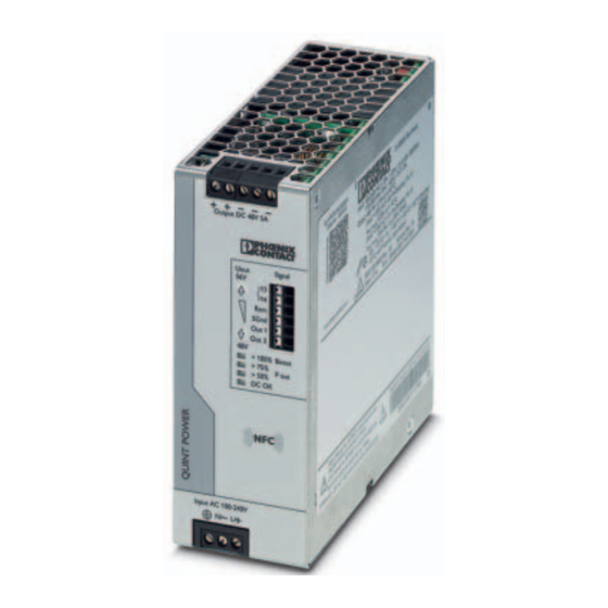
QUINT4-PS/1AC/48DC/5
Power supply unit
Data sheet
108476_en_01
1
Description
QUINT POWER power supplies with SFB Technology and
preventive function monitoring ensure superior system
availability.
Powerful
–
SFB technology: 6 times the nominal current for 15 ms
–
Power reserves:
Static boost of up to 125% (P
Dynamic boost of up to 200% (P
Robust
–
Mains buffering ≥ 20 ms
–
High degree of electrical immunity, thanks to integrated
gas-filled surge arrester (6 kV)
Preventive
–
Comprehensive signaling:
Analog signal, digital signal, relay contact, LED bar
graph
Can be ordered pre-configured
–
Perform configuration online and order 1 or more units
All technical specifications are nominal values and refer to a room temperature of 25 °C and 70 % relative
humidity at 100 m above sea level.
© PHOENIX CONTACT
) for a sustained period
N
) for 5 s
N
2018-09-05
Technical data (short form)
Input voltage range
Mains buffering
Nominal output voltage (U
)
N
Setting range of the output voltage
(U
)
Set
Nominal output current (I
)
N
Static Boost (I
)
Stat.Boost
Dynamic Boost (I
)
Dyn.Boost
Selective Fuse Breaking (I
)
SFB
Output power (P
)
N
Output power (P
)
Stat. Boost
Output power (P
)
Dyn. Boost
Efficiency
Residual ripple
MTBF (IEC 61709, SN 29500)
Ambient temperature (operation)
Dimensions W/H/D
Weight
100 V AC ... 240 V AC
-15 % ... +10 %
≥ 40 ms (120 V AC)
≥ 40 ms (230 V AC)
48 V DC
48 V DC ... 56 V DC
5 A
6.25 A
10 A (5 s)
30 A (15 ms)
240 W
300 W
480 W
typ. 92.3 % (120 V AC)
typ. 93.5 % (230 V AC)
< 70 mV
PP
> 784000 h (40 °C)
-25 °C ... 70 °C
-40°C (startup type tested)
> 60 °C Derating: 2.5 %/K
50 mm / 130 mm / 125 mm
1 kg
Advertisement
Table of Contents

Related Manuals for Phoenix Contact QUINT4-PS/1AC/48DC/5


Summary of Contents for Phoenix Contact QUINT4-PS/1AC/48DC/5
-
Page 1: Description
QUINT4-PS/1AC/48DC/5 Power supply unit Data sheet 108476_en_01 © PHOENIX CONTACT 2018-09-05 Description QUINT POWER power supplies with SFB Technology and preventive function monitoring ensure superior system Technical data (short form) availability. Input voltage range 100 V AC ... 240 V AC -15 % ... -
Page 2: Table Of Contents
Mounting/removing the power supply ..................21 Device connection terminal blocks ..................24 Output characteristic curves ....................26 Configuring the power supply ....................29 Boost currents ........................30 SFB technology ........................32 Signaling..........................36 Operating modes ........................44 Derating..........................46 108476_en_01 PHOENIX CONTACT 2 / 49... -
Page 3: Ordering Data
Near Field Communication (NFC) programming adapter TWN4 MIFARE NFC USB 2909681 with USB interface for the wireless configuration of NFC- ADAPTER capable products from PHOENIX CONTACT with software. No separate USB driver is required. Type 2/3 surge protection, consisting of protective plug PLT-SEC-T3-230-FM-UT 2907919 and base element, with integrated status indicator and remote signaling for single-phase power supply networks. -
Page 4: Technical Data
The SCCR value (short-circuit current rating) of the power supply unit corresponds to the SCCR value of the backup fuse (see input protection table). The external backup fuse must be approved for the (AC) supply voltage used and the voltage level. 108476_en_01 PHOENIX CONTACT 4 / 49... - Page 5 0.5 kV DC 0.5 kV DC 2.83 kV DC 2.83 kV DC POWER factor = U : 120 V AC/U : 48 V DC = U : 230 V AC/U : 48 V DC 108476_en_01 PHOENIX CONTACT 5 / 49...
- Page 6 Control deviation change in input voltage ±10 % < 0.25 % Short-circuit-proof No-load proof Residual ripple ( with nominal values ) < 70 mV Connection in parallel Yes, for redundancy and increased capacity Connection in series 108476_en_01 PHOENIX CONTACT 6 / 49...
- Page 7 24 V DC 1 A , 30 V AC/DC 0.5 A Control input (configurable) Rem Function Output power ON/OFF (SLEEP MODE) Default Output power ON (>40 kΩ/24 V DC/open bridge between Rem and SGnd) Signal ground SGnd Reference potential for Out1, Out2, and Rem 108476_en_01 PHOENIX CONTACT 7 / 49...
- Page 8 230 V AC Maximum power dissipation in no-load condition < 3 W < 3 W Power dissipation SLEEP MODE < 3 W < 3 W Power loss nominal load max. < 19 W < 16 W 108476_en_01 PHOENIX CONTACT 8 / 49...
- Page 9 SEMI F47-0706; EN 61000-4-11 Rail applications EN 50121-3-2 EN 50121-4 EN 50121-5 IEC 62236-3-2 IEC 62236-4 IEC 62236-5 EMC requirements, power plant IEC 61850-3 EN 61000-6-5 HART FSK Physical Layer Test Specification Compliance Output voltage U compliant 108476_en_01 PHOENIX CONTACT 9 / 49...
- Page 10 QUINT4-PS/1AC/48DC/5 Approvals UL Listed UL 508 UL/C-UL Recognized UL 60950-1 UL ANSI/ISA-12.12.01 Class I, Division 2, Groups A, B, C, D (Hazardous Location) CAN/CSA-C22.2 No. 60950-1-07 CSA-C22.2 No. 107.1-01 108476_en_01 PHOENIX CONTACT 10 / 49...
- Page 11 2 kV (Test Level 3 - 4 kV (Test Level 4 - asymmetrical) asymmetrical) Signal 1 kV (Test Level 3 - 4 kV (Test Level 4 - asymmetrical) asymmetrical) Comments Criterion B Criterion A 108476_en_01 PHOENIX CONTACT 11 / 49...
- Page 12 0 % , 0,5 / 1 / 5 / 50 / 250 ( Test Level 2 ) periods ( Test Level 2 ) Comments Criterion B Criterion A: 0.5 / 1 period Criterion B: 5 / 50 / 250 periods 108476_en_01 PHOENIX CONTACT 12 / 49...
- Page 13 ( Test Level 3 - symmetrical ) 1 MHz , 2.5 kV 100 kHz , 1 MHz , 2.5 kV ( Test Level 3 - asymmetrical ) ( Test Level 3 - asymmetrical ) Comments Criterion B Criterion A 108476_en_01 PHOENIX CONTACT 13 / 49...
- Page 14 Temporary impairment to operational behavior that is corrected by the device itself. Criterion C Temporary adverse effects on the operating behavior, which the device corrects automatically or which can be restored by actuating the operating elements. 108476_en_01 PHOENIX CONTACT 14 / 49...
-
Page 15: Safety And Installation Notes
Never carry out work when mains voltage is present. CAUTION: Hot surface Depending on the ambient temperature and load on the power supply, the housing can become hot. 108476_en_01 PHOENIX CONTACT 15 / 49... -
Page 16: High-Voltage Test (Hipot)
IEC/UL/EN 60950-1. The high-voltage test is performed with a test voltage of at least 1.5 kV AC / 2.2 kV DC or higher. Routine manufacturing tests are inspected regularly by a certification body. 108476_en_01 PHOENIX CONTACT 16 / 49... - Page 17 Potential 1 Signal contacts Blue Potential 1 To connect the gas-filled surge arrester, only use the gas-filled surge arrester screw that High-voltage was originally installed in the power supply. tester AC input circuit Potential 2 108476_en_01 PHOENIX CONTACT 17 / 49...
-
Page 18: Structure Of The Power Supply
NFC interface (Near Field Communication) AC input voltage connection terminal blocks Gas-filled surge arrester for surge protection (left side of housing) Universal DIN rail adapter (rear of housing) Output voltage button (-) / (+) 108476_en_01 PHOENIX CONTACT 18 / 49... - Page 19 Output DC 48V 5A Signal SGnd Out 1 Out 2 > 100% Boost > 75% > 50% DC OK DC OK Input AC 100-240 V N/- L/+ Figure 6 Device dimensions and minimum keep-out areas (in mm) 108476_en_01 PHOENIX CONTACT 19 / 49...
- Page 20 Switching transistor and main transmitter NFC interface (Near Field Communication) (electrically isolating) Output voltage button (-) / (+) Secondary rectification and smoothing Filter Signal/display LEDs (P , DC OK) Auxiliary converter (electrically isolating) 108476_en_01 PHOENIX CONTACT 20 / 49...
-
Page 21: Mounting/Removing The Power Supply
Carefully swivel the power supply forward (C) so that the lock slides back into the starting position. Then separate the power supply from the DIN rail (D). Figure 10 Disassembling the universal DIN rail adapter 108476_en_01 PHOENIX CONTACT 21 / 49... - Page 22 Make sure you use suitable mounting material when attaching to the mounting surface. The power supply is attached to the UWA 182 or UWA 130 universal wall adapter by means of the Torx screws of the universal DIN rail adapter. 108476_en_01 PHOENIX CONTACT 22 / 49...
- Page 23 Make sure that the connection wiring is attached safely and securely without damaging the connection wiring. Figure 13 Mounting the UWA 130 universal wall adapter S i g > 1 > 7 > 5 Figure 15 Secure connection wiring with cable binder 108476_en_01 PHOENIX CONTACT 23 / 49...
-
Page 24: Device Connection Terminal Blocks
The additional insulation material for protecting the connection wiring is limited to the area where the cable binders are attached. − − − − − − − − Figure 17 Network types 108476_en_01 PHOENIX CONTACT 24 / 49... - Page 25 Pin assignment for AC supply voltage Protection for DC supply Input DC 110...250 V Figure 19 Pin assignment for DC supply voltage DC applications require upstream installation of a fuse that is permitted for the operating voltage. 108476_en_01 PHOENIX CONTACT 25 / 49...
-
Page 26: Output Characteristic Curves
Characteristics U/I Advanced Smart HICCUP FUSE MODE Symbol Designation Suitable for the application Not suitable for the application 108476_en_01 PHOENIX CONTACT 26 / 49... - Page 27 Stat. Boost 100% 125% 200% Stat. Boost 100% 125% 200% Dyn. Boost t [s] Dyn. Boost Figure 21 Smart HICCUP output characteristic curve t [s] Figure 20 U/I Advanced output characteristic curve 108476_en_01 PHOENIX CONTACT 27 / 49...
- Page 28 Selecting the FUSE MODE output characteristic curve sets the following default values. – = 100 ms Fuse – Fuse Fuse Fuse t [s] Figure 22 FUSE MODE output characteristic curve 108476_en_01 PHOENIX CONTACT 28 / 49...
-
Page 29: Configuring The Power Supply
If a connection cannot be established between the USB-PROG-ADAPTER and the power supply, more detailed information can be found in the user manual for the QUINT POWER software. 108476_en_01 PHOENIX CONTACT 29 / 49... -
Page 30: Boost Currents
(see recovery time tables). You can type in the the web code phoenixcontact.net/webcode/#0852 to configure and order your power supply. Dyn.Boost Dyn.Boost Dyn.Boost Pause Base Load t [s] Figure 26 Basic curve of the dynamic boost process 108476_en_01 PHOENIX CONTACT 30 / 49... - Page 31 Example recovery time for ≤ 40°C 6,25 Figure 27 Required recovery times at ≤ 40°C 12.2.2 Recovery times at an ambient temperature of 60 °C Dyn. Boost Dyn. Boost Base Load Figure 28 Required recovery times at ≤ 60°C 108476_en_01 PHOENIX CONTACT 31 / 49...
-
Page 32: Sfb Technology
Fuses are tripped by melting the predetermined breaking point inside the fuse capsule. The tripping characteristic of the fuse is described by the melting integral (I²t). A high current is crucial in order to achieve a very short tripping time. 108476_en_01 PHOENIX CONTACT 32 / 49... - Page 33 The distances given in the table are worst-case values and therefore cover the entire tolerance range for the magnetic tripping of circuit breakers. The possible distances are often greater in practice. 13.4.1 Thermomagnetic device circuit breaker, type: Phoenix Contact CB TM1 SFB Maximum distance l [m] with device circuit...
- Page 34 Internal resistance R of the device circuit taken into consideration breaker: Comments: In addition to the short-circuit current, the power supply unit also supplies half the nominal current for load paths connected in parallel. 108476_en_01 PHOENIX CONTACT 34 / 49...
- Page 35 Ambient temperature: +20 °C Internal resistance R of the fuse: taken into consideration Comments: In addition to the short-circuit current, the power supply unit also supplies half the nominal current for load paths connected in parallel. 108476_en_01 PHOENIX CONTACT 35 / 49...
-
Page 36: Signaling
Out 2 (digital or analog output, function depends on the signal option set) LED status indicator DC-OK LED on: U > 90% x U LED flashing: U < 90 % x U LED status indicator >50% (output power >120 W) LED status indicator >75% (output power >180 W) LED status indicator P >100%, boost mode (output power >240 W) 108476_en_01 PHOENIX CONTACT 36 / 49... - Page 37 Signal Digital Input SGnd Out 1 DI x 0/24 V DC Out 2 DI x 0/24 V DC Figure 34 Signaling 108476_en_01 PHOENIX CONTACT 37 / 49...
- Page 38 The simultaneous control of multiple signal outputs by means of one signal option is possible, as is the use of logic operations to link multiple signal options to one control. The power supply is configured using the QUINT POWER software or the QUINT POWER app. 108476_en_01 PHOENIX CONTACT 38 / 49...
- Page 39 Before the power supply protects itself through power derating in the event of an overtemperature, the signal state changes. Example of use Outdoor control cabinets can reach a high internal temperature depending on the position of the sun. The same 108476_en_01 PHOENIX CONTACT 39 / 49...
- Page 40 Signal < 40 k operates in boost mode. In boost mode, the > 100% LED additionally lights up yellow. SGnd Out 1 Out 2 Figure 37 External wiring versions, disable SLEEP MODE 108476_en_01 PHOENIX CONTACT 40 / 49...
- Page 41 LED: DC OK Closed Relay: 13/14, DC OK Closed Open Default Signal Out 1: DC OK Active High Active High Active Low LED off LED on LED flashing Figure 40 Signal image for SMART HICCUP 108476_en_01 PHOENIX CONTACT 41 / 49...
- Page 42 Active Low LED off LED on LED flashing Figure 41 Signal image for FUSE MODE 14.9 SLEEP MODE signaling In SLEEP MODE, all LEDs are off, all signals are low, and the relay switching contact is open. 108476_en_01 PHOENIX CONTACT 42 / 49...
- Page 43 IEC/EN 61850-3 or signal connection types 3 (process area) and 4 (high voltage area) in accordance with EN 61000-6-5. When using the digital signals, a relay (Phoenix Contact Order No.: 2900299 or a comparable relay) can be implemented. 14.10.2 Surge protection for signals in railway applications Surge protection (Phoenix Contact Order No.: 2905223 or comparable protection) must be implemented for railway...
-
Page 44: Operating Modes
We recommend the configuration "parallel operation" for a parallel connection. For more detailed information on the operating mode for parallel operation, refer to the user manual for the QUINT POWER software or the QUINT POWER app. 108476_en_01 PHOENIX CONTACT 44 / 49... - Page 45 . Parallel connection for increased power is used when extending existing systems. If the individual power supply does not cover the current consumption of the most powerful load, parallel connection of power supplies is recommended. 108476_en_01 PHOENIX CONTACT 45 / 49...
-
Page 46: Derating
Output power depending on the ambient temperature 16.2 Input voltage Derating 1 %/V < 100 V AC ≤ 60 °C < 110 V DC 24 V DC < 115 V AC ≤ 40 °C Stat. Boost < 110 V DC 108476_en_01 PHOENIX CONTACT 46 / 49... - Page 47 125 % Stat. > 1 > 7 200 % > 5 Dyn. -25 0 T [°C] 16.4.2 Rotated mounting position 90° Z-axis 100 % 125 % Stat. 200 % Dyn. -25 0 T [°C] 108476_en_01 PHOENIX CONTACT 47 / 49...
- Page 48 16.4.3 Rotated mounting position 180° Z-axis 100 % 125 % Stat. 200 % Dyn. -25 0 T [°C] 16.4.4 Rotated mounting position 270° Z-axis 100 % 125 % Stat. 200 % Dyn. -25 0 T [°C] 108476_en_01 PHOENIX CONTACT 48 / 49...
- Page 49 200 % Dyn. -25 0 T [°C] 16.4.6 Rotated mounting position 270° X-axis 100 % 125 % Stat. 200 % Dyn. -25 0 T [°C] PHOENIX CONTACT GmbH & Co. KG • 32823 Blomberg • Germany 108476_en_01 49 / 49 phoenixcontact.com...
Need help?
Do you have a question about the QUINT4-PS/1AC/48DC/5 and is the answer not in the manual?
Questions and answers