
Subscribe to Our Youtube Channel
Related Manuals for Hillyard TRIDENT T20SC PRO


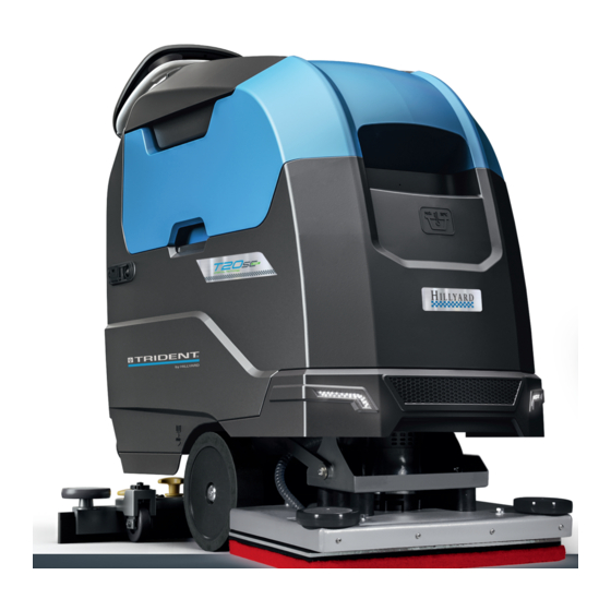
Summary of Contents for Hillyard TRIDENT T20SC PRO
- Page 1 SERVICE MANUAL TRIDENT T20SC PRO Version: AB Date: November 7, 2018 Document Number:10077483...
-
Page 2: Table Of Contents
Contents I Product Introduction 1 Serial Number and Technical Support 1.1 The Serial Tag ....... . . 1.2 Serial Tag location . - Page 3 6 Mechanical Rubbing System 6.1 Description ........47 6.2 Adjustments .
-
Page 4: I Product Introduction
Part I Product Introduction... -
Page 5: Serial Number And Technical Support
Chapter 1 Serial Number and Technical Support The Serial Tag Serial Tag location To have access to the Serial Tag is necessary to lift the recovery tank. The Serial Number is an extremely important information which has to be provided each time a Technical Support is required or is necessary to buy spare parts or accessories. -
Page 6: Main Technical Features
Chapter 2 Main Technical Features Technical Data TECHNICAL DESCRIPTION T20SC PRO Traction Motor 24-180 (Voltage - Nominal Power) Ramp Gradient in transport Max speed in transport (Default) Supply/Traction 24-Aut. Vacuum Motor 24-420 (Voltage - Nominal Power) Vacuum motor Stages Vacuum group suction mbar 91,4 Steering diameter... - Page 7 Technical Data T20SC PRO TECHNICAL DESCRIPTION Disc Orbital Working width Working capacity, up to 19200 19200 Total Power 1090 1150 Brushdeck Motor Nr-V-W 1-24-500 1-24-560 (Number - Voltage - Nominal Power) Disc Brushes (Number - External Ø) Nr-Øin 1-20 Brushes revolutions Rectangular Pad Nr-in-in 1-20-14...
-
Page 8: Anomalies Resolution Guide
Part II Anomalies Resolution Guide... -
Page 9: Trouble-Shooting For The Most Common Anomalies
Chapter 3 Trouble-shooting for the most common anomalies Electrical system: what to do if. . . The machine doesn’t switch on 1. The key is in position 0 Rotate the key in position I. 2. The key microswitch is not properly Restore the proper connections. - Page 10 The batteries don’t work properly 1. The batteries are not properly con- Connect properly the loop cable and nected the power supply cables. 2. Battery are discharged Perform a complete charge cycle. 3. Battery terminal are oxidized Disconnect the batteries, clean the batteries terminals and reconnect properly the batteries.
- Page 11 The display shows an alarm message 1. The display shows an alarm mes- Check what alarm message is sage shown and solve the related issue by following the proper instructions (see section at page 16) The machine has a very limited working autonomy 1.
-
Page 12: Mechanical Scrubbing System: What To Do If
Mechanical scrubbing system: what to do if. . . The machine doesn’t clean well The machine is switched off Switch on the machine. The machine doesn’t switch on Refer to the proper section (see section at page 8) The display shows an alarm mes- Check what alarm message is sage shown and solve the related issue... -
Page 13: Drying System: What To Do If
Drying system: what to do if. . . The machine doesn’t dry well The machine is switched off Switch on the machine. The machine doesn’t switch on Refer to the proper section (see section at page 8) The recovery tank is full Empty the recovery tank following the proper procedure. - Page 14 The vacuum motor doesn’t work properly 1. The vacuum motor is switched off Switch on the vacuum motor. 2. The vacuum motor is not powered Check the power connections on the properly vacuum motor. 3. The display shows an alarm mes- Check what alarm message is sage shown and solve the related issue...
-
Page 15: Frame And Traction System: What To Do If
Frame and traction system: what to do if. . . The traction motor doesn’t work properly The machine is switched off Switch on the machine. The machine doesn’t switch on Check the proper section (see section at page 8) The display shows an alarm mes- Check what alarm message is sage shown and solve the related issue... -
Page 16: Solution Delivery System: What To Do If
Solution delivery system: what to do if. . . The delivered solution is not correct or not enough 1. The machine is switched off Switch on the machine. The machine doesn’t switch on Refer to the proper section (see section at page 8) The solution tank is empty Fill up the solution tank. -
Page 17: Alarm Table
Alarm Table 3.6.1 Alarms of Overcurrent and Temperature Id Alarm Meaning Solution AL 1: Function Brush Amperometric Protection Check consumption of the brush motor. Detected high current Amp. Brush on brush motor. AL 2: Function Vacuum Amperometric Protec- Check consumption of the vacuum motor. Detected high cur- Amp. - Page 18 3.6.3 General Alarms Id Alarm Meaning Solution AL 20: General Error reading internal memory Replace the main card. EEprom malfunction AL 21: General Error key sequence Error on key signal: Switch off the machine, wait at least 2 seconds and switch it on again. If the problem persists, re- place the key block.
-
Page 19: Disassembling Procedures
Chapter 4 Disassembling Procedures ARNING EFORE TO PERFORM ANY OPERATION DESCRIBED BELOW VERIFY THAT THE MACHINE TANKS ARE COMPLETELY EMPTY THE MACHINE HAS TO BE TURNED ISCONNECT THE BATTERIES AND REMOVE THEM FROM THE MACHINE T LAST VERIFY THAT THE PARKING BRAKE IS ENGAGED AND THE MACHINE IS IN A TOTALLY SAFE CONDITION... -
Page 20: Electrical Installation
Electrical Installation • Remove the chosen component: – Key Microswitch 4.1.1 Handlebar Compo- nents – Safety Microswitch – Potentiometer • Put the machine in safe conditions. – Emergency button • Tilt the recovery tank (see fig. 4.1.1-1) – Gun/Spray switch •... -
Page 21: Mechanical Friction System
• Remove the electrical system cover by removing the screws (see fig. 4.1.2-7) • Disconnect all the cables, remove the 4 screws securing the board to the panel and remove it (see fig. 4.1.2-8) 4.1.3-10 4.1.3-11 • Disconnect the Actuator Board from the connector of the Main Board (see Mechanical... - Page 22 4.2.3 Brush Motor - Disc • Put the machine in safe conditions. • Disassemble the Brush Coupling Flange (see section 4.2.2 at page 20) 4.2.1-12 4.2.1-13 • Unplug the Solution Hose that con- nects the Solenoid Valve to the Brush Motor. •...
-
Page 23: Drying System
4.2.5 Brush Motor - Orbital • Release the plug and disconnect the actuator arm from the brush deck • Put the machine in safe conditions. arm. • Disassemble the complete Brush • Remove the elastic ring, and remove Deck (see section 4.2.4 at page 21) the actuator from its support... - Page 24 • Loose the screws that block the Squeegee Rotation Arm to the Ma- chine Chassis. • Remove the Squeegee Rotation Arm. • Proceed at reverse to refit the part taking care about the bushing posi- tioning. 4.3.2 Squeegee adjustment wheels •...
-
Page 25: Frame And Traction System
4.3.5 Vacuum Cover • Put the machine in safe conditions. • Tilt the recovery tank. • Unscrew the pivot covering cap (see fig. 4.3.6-29 4.3.6-30 4.3.5-27) • Extract the pin with the help of a pli- (see fig. 4.3.5-28) • Proceed at reverse to refit the part. 4.3.6-31 Frame Traction... -
Page 26: Solution Delivery System
4.4.2 Traction Gearmotor • Remove the recovery tank (see section and the elec- 4.3.4 at page 23) (see fig. 4.5.1-37) • Put the machine in safe conditions. tric system carter (see fig. 4.5.1-38) • Disassemble both wheels (see section • Remove the handlebar and the elec- 4.4.1 at page 24) trical system panel... - Page 27 • Remove the lower carters and the • If necessary, remove the coil screw water assembly and remove it (see fig. 4.5.1-45) (see fig. 4.5.3-49) • Proceed at reverse to refit the part • Remove the remaining parts (see fig. (Position the spacer washer properly 4.5.1-46) to refit the valve to the brush deck...
-
Page 28: Machine Description
Part III Machine Description... -
Page 29: Electrical System
Chapter 5 Electrical System Structure T20SC PRO Description T20SC A main board runs all the functions of the machine, washing, drying, traction and braking. The main board receive as input, all the information from the control board, the safety microswitch and all the electronic devices of the machine. -
Page 30: Location Of Electrical Components
Location of Electrical components... - Page 31 5.3.1 List of Components 4 Key Microswitch 5 Emergency Button 8 Vacuum Motor Microwitch 9 Safety Microwitch 10 Solenoid Valve 11 Electro brake 12 Potentiometer 13 Gun/Wand activation switch 14 Recycle/Dosing system Switch 15 Forward/Backward switch 16 Brush extra pressure switch 17 Display hourmeter/BDI 21 Main Board K Key...
- Page 32 5.3.2 Main Board T20SC PRO The Main Board is the heart of the machine and, depending of the input informa- tion, decides how to use the devices of the machine during normal work. On the table here below, is possible to identify the input/output signals of the board. Board Cables Legend Power Contacts Traction Motor...
- Page 33 Traction Potentiometer Yellow Positive Traction Potentiometer Green Negative Recovery Empty Floater Orange Battery Positive Gray Positive Electrobrake Black Solenoid Valve White Recycle Pump / Detergent Yellow Potentiometer Signal Brown Solution Empty Floater Gray Squeegee Microswitch Purple Safety Microswitch L. Blue Battery Positive Positive Green...
- Page 34 5.3.3 Dashboard Functions and Commands During the normal working, the dis- play shows the hourmeter and the bat- tery control board (in percentage). When the charge of the batteries goes down to a fixed value, the battery control board disable the brush motor and, after that, the vacuum motor;...
- Page 35 5.3.4 Control Board 5.3.6 Potentiometer The Control Board is located inside of The adjustment knob of the potentiome- the dashboard panel and transfers all ter, located on the control panel, allows the information and settings to the Main to adjust the speed of the machine, and Board.
-
Page 36: Adjustments
Adjustments 5.4.1 Charger (CB) The charger is located on the rear side of the machine and easy to access for the operator. When connected to the power supply, a red led will blink once, the yellow led blink once and the green led blink depending of the type of battery for which the charger is set. - Page 37 Set-up of Charging Curve DP1 DP2 DP4 Set Up Yellow LED Green LED Flash OFF OFF OFF IUI0-Pb Flooded OFF IUoU-Gel Trojan OFF ON OFF IUoU-AGM GEL OFF OFF IUI0-Gel Sonnenschein OFF OFF ON IUIa-Pb Flooded IUI0-AGM EV-Discover OFF ON IUa-AGM Zenith OFF ON IUIa-Gel Sonnenschein...
-
Page 38: Maintenance And Checks
Maintenance 5.4.2 ECO Function Checks Press the ECO button, and let the vac- uum motor and the brush motor work. with the ECO mode activated, check if 5.5.1 Electrical System the noise of the vacuum motor and the Check (to perform every 150h) brush motor is reduced. -
Page 39: Programming
Programming 5.6.2 How to access the Opera- tor Menu 5.6.1 Entry into the Operator Menu and Advanced Menu To enter to the Operator menu go ahead as follow: The Display allows the access to basic • With the machine off, press in the settings with free access and to the same time button 2 &... - Page 40 5.6.3 How to Change a Pa- 5.6.4 For example, to modify the rameter (in the Operator language from GEL60 to Menu) Pb60 To change the value of a parameter pro- • Turn OFF the machine. ceed as follows: • With the machine off, press at the •...
- Page 41 5.6.5 How to access the Ad- 5.6.6 Use of the Monitor Mode vanced Menu Function The Check / Monitor function allows to The Advanced Menu can be reached check from the Operator Menu by accessing - The battery status the –ID check– parameter and setting - The motors absorption the value 60.
-
Page 42: Menu Tables
Menu Tables 5.7.1 Menu Tree • Make sure the machine is turned off. • Press simultaneously the buttons 3,4,6. • Turn on the machine while holding down the buttons. • Wait the loading of the Operator Menu. • For the submenus of the Advanced Menu, refer to the specific tables. - Page 43 5.7.2 Working Menu MENU DEFAULT CHOICES DESCRIPTION General Setup: IT-EN-FR-SP- Setup language Language General Setup: BT-BTO Setup of the machine model BT=Disc BTO=Orbital General Setup: Gel60 Pb60-Gel60- Setup of the battery type Battery PPb-Pb80- Gel80 General Setup: Partial hourmeter reset Reset Cnt Selection of the hourmeter type: Key connected to the Key - General Setup:...
- Page 44 General Sets MENU DEFAULT VALUES DESCRIPTION General Sets: IT-EN-FR-SP- Setup the language of the machine interface text. Language General Sets: BT-BTO Setup of the machine model BT=Disc BTO=Orbital General Sets: Gel60 Pb60-Gel60- Setup of the battery type. Battery PPb-Pb80- Gel80 General Sets: Reset partial hourmeter (like on “working menu”).
- Page 45 Water Pump Sets Parameter Default Description Water Flow Sets: First level water flow setting. If HDC or Spray is activated the default is 25. Flow1 sets: [%] Water Flow Sets: Second level water flow setting. If HDC or Spray is activated the default is 50. Flow2 sets: [%] Water Flow Sets: Third level water flow setting.
- Page 46 Traction Sets Parameter Default Description Traction Sets: Acceleration ramp. The time necessary to arrive at the maximum Acc. Ramp: [s] speed. Traction Sets: Deceleration ramp. The time necessary to stop the machine when the Dec. Ramp: [s] safety lever is released. Traction Sets: The time necessary to invert the way.
- Page 47 Monitor Mode Monitor Sets: NOT USED. No Monitor: Monitor Sets: Show battery voltage. Battery: [V] Monitor Sets: Show voltage of traction motor. Traction Voltage: [V] Monitor Sets: Show current of traction motor. Traction Current: [A] Monitor Sets: Maximum overload of traction motor. Tract.
-
Page 48: Mechanical Rubbing System
Chapter 6 Mechanical Rubbing System Description The washing function of the machine is obtained by the interaction of the clean- ing solution with the dirt present on the floor. To facilitate and enhance this interac- tion, is used a system of mechanical rub- bing which consists in a device which rubs on the floor. - Page 49 Figure 6.1: T20SC PRO Figure 6.2: T20SC ORBITAL PRO 6.1.1 Structure T20SC PRO 6.1.3 Structure T20SC BITAL PRO • Motor • Motor • Brush coupling Flange • Brush Deck and Support • Brush Deck • Eccentric Flange • Bumper wheel •...
-
Page 50: Adjustments
Adjustments 6.2.1 T20SC PRO The scrub deck is tilted in the transverse direction and should be adjusted longi- tudinally inclined to the machine so that 6.2.1-1 6.2.1-2 the brushes have a distance of about inch from the floor, larger on the front than on the rear side. -
Page 51: Maintenance And Checks
6.2.3 Scrub Deck Actuator must be less than 25 Ampere in stan- dard mode and less than 37 Ampere in T20SC PRO Power mode. The scrub deck actuator does not need The motor should rotate evenly and any particular adjustment, if neces- smoothly and doesn’t have to produce sary check that the two internal mi- unusual noises. - Page 52 6.3.2 Brush Deck • Remove the screws that secure the base to the machine body. Check (to perform every 150h) The brush deck must be kept clean and intact. A ruined deck may be danger- ous to the machine and the operator that uses it.
-
Page 53: Drying System
Chapter 7 Drying System Description The machine dries the floor using an in- tegrated Drying System. After the washing, the solution used with the mechanical action of the brush to remove the dirt, is collected by a sys- tem which vacuum it out from the floor. The system is basically made by a vac- uum motor which produces an under- pressure in the system. -
Page 54: Adjustments
Adjustments • Check functionally the resulting ad- justment. 7.3.1 Squeegee Support The Squeegee Support has to be ad- justed with the Squeegee fitted on, low- ered on the floor and vacuum system on. The goal of the adjustment is to let the squeegee blade be angled 45 degrees to the floor for its whole length. - Page 55 • Proceed at reverse to reinstall prop- erly the blade holders. 7.4.2-8 7.4.2-9 • At the end of the assemblying per- 7.4.1-4 7.4.1-5 form the proper squeegee adjust- ment (see section 7.3.1 at page 53) 7.4.3 Vacuum Hose Check (to perform every 4h) The vacuum hose , has to be (see fig.
- Page 56 7.4.5 Recovery Tank 7.4.7 Vacuum Motor Check Check (to perform every 150h) (to perform every 150h) The recovery tank has to be clean and The vacuum motor with the inlet com- has not to have cracks or, in general, any pletely open has to absorb between 15 kind of damage.
-
Page 57: Machine Frame And Traction System
Chapter 8 Machine Frame and Traction System Description The frame is a single structure on which are coupled the traction system and the tanks group. The machine traction is given by the electric motor installed with a reduction gear, whose output shafts act directly on the machine front wheels, ensuring trac- tion. -
Page 58: Maintenance And Checks
Maintenance Maintenance (to perform every 600h) Checks Replacement of traction motor Carbon Brushes: 8.3.1 Wheels Procedure: Check (to perform every 150h) • Secure the machine. The wheel must be free to rotate smoothly without friction. The wheel • Remove the traction unit from the surface, must always be in good condi- machine (see section... -
Page 59: Cleaning Solution Supply System
Chapter 9 Cleaning Solution Supply System Description The Cleaning Solution Supply System is made by a tank commonly called so- lution tank or clean water tank. In this tank the clean water is mixed with the detergent to create the clean- ing solution that the machine will use to clean. -
Page 60: Maintenance And Checks
Maintenance Checks 9.3.1 Solution Tank Check (to perform every 50h) 9.3.4-1 9.3.4-2 The solution tank has to be clean and intact. It has not to have cracks or any other kind of damage. Verify, when the tank is completely filled up, that there deck is not working. -
Page 61: Consumable & Recommended Spare Parts
Chapter 10 Consumable & Recommended Spare Parts 10.1 Consumable Spare Parts 10.1.1 Mechanical Rubbing System T20SC PRO Description (in) Bristle Bristle (in) Colour 404654 BRUSH PPL 0,3 0,012 Blue 405631 BRUSH PPL 0,6 0,023 White 404653 BRUSH PPL 0,9 0,035 Black 405632 BRUSH TYNEX... - Page 62 10.1.2 Drying System Description Rear Rubber Dimensions Squeegee 27 in 227172 RUBBER KIT PARA 33Sh 31 x 2.5 x 0.25 in 227173 RUBBER KIT PARA 40Sh 31 x 2.5 x 0.25 in 227174 RUBBER KIT POLY 40Sh 31 x 2.5 x 0.25 in 227175 RUBBER KIT Linatex 30Sh 31 x 2.5 x 0.25 in...
-
Page 63: Recommended Spare Parts
10.2 Recommended Spare Parts The following table refers to the Recommended Spare Parts, and reports the amount suggested by the number of purchased machines. Machines Parts 10.2.1 Electrical System Description 436434 CHARGER NE284-F 24V 15A 227019 KEY (NO HFM) 227287 KEY (HFM) 409491 KEY MICROSWITCH... - Page 64 10.2.3 Drying System Description 436120 BUMPER WHEEL D=100 H=20 227727 VACUUM MOTOR 24V 422W 2ST 433652 FLOATER PROTECTION D.110 x 182 412363 CARTRIDGE FILTER ASSEMBLY D=60 H=130 436190 GAS SPRING L=146 150N 445710 DRAIN HOSE D.38x1100 D.50+CAP 445709 VACUUM HOSE D=38 L=1450 10.2.4 Machine Frame and Traction System Description...
- Page 65 Hillyard, Inc. Service Manual TRIDENT T20SC PRO Hillyard, Inc. 302 North 4th Street - P .O. Box 909 St. Joseph, Missouri 64501 - USA Tel. 1-800-365-1555 - Fax 1-800-881-3840 Edition: November 7, 2018...
Need help?
Do you have a question about the TRIDENT T20SC PRO and is the answer not in the manual?
Questions and answers
On my display Alarm Function, ACT1: endsw fail
The "ACT1: endsw fail" alarm indicates an anomaly in the reading of the brush deck actuator microswitch. It occurs when, at machine startup, one microswitch is open. The solution is to check the scrub deck microswitches, their cables, and the scrub deck position.
This answer is automatically generated