
Related Manuals for Hillyard TRIDENT R36 SC PLUS


Summary of Contents for Hillyard TRIDENT R36 SC PLUS
- Page 1 Scrubbing machine Use and Maintenance manual Instructions originales - DOC. 10076229 - Ver. AA - 06-2018...
-
Page 3: Main Machine Components
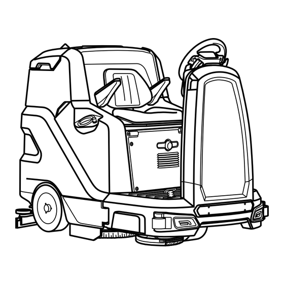
MAIN MACHINE COMPONENTS The machine's main components are the following: Front working lights. Blinking light. Operator seat. Emergency button. Blinking lights switch. Left hatch. Recovery tank lid. Recovery tank. Solution tank. Right hatch. Side scrubbing brush head (version 1SL). Recovery tank drainage hose. Tail lights. -
Page 4: Table Of Contents
CONTENTS MAIN MACHINE COMPONENTS ..........3 DETERGENT SOLUTION RECYCLING SYSTEM (OPTIONAL) ..24 CONTENTS ................4 AUTOMATIC REQUEST FOR TECHNICAL ASSISTANCE GENERAL SAFETY REGULATIONS ........5 (OPTIONAL) ..................24 AUTOMATIC DETERGENT DOSING SYSTEM (OPTIONAL) ..24 RECHARGING THE BATTERIES ............5 TUTORIAL ..................25 USING THE MACHINE ............... -
Page 5: General Safety Regulations
GENERAL SAFETY REGULATIONS The following symbols are used to indicate any potentially hazardous situations. Always read this information carefully and take the necessary precautions to protect any people and/or objects that may be present. Operator cooperation is paramount for accident prevention. No accident prevention programme can be effective without the full cooperation of the person directly responsible for the machine's operation. -
Page 6: Using The Machine
WARNING: • Do not use incompatible battery chargers since they could damage the batteries and potentially cause a fire. • The batteries emit hydrogen gas. This gas can cause explosions or fires. Keep a safe distance from flames or sparks. Keep the recovery tank open for the duration of the battery recharging. •... - Page 7 • Do not use the machine if you have not read and understood the following user manual. • Do not use the machine under the influence of alcohol or drugs. • Do not use the machine when using a mobile phone or other types of electronic devices. •...
-
Page 8: Deactivation Of The Machine
warnings indicated on the containers' labels. • Always use appropriate gloves and protective equipment when handling the detergents used to clean the floor. • Do not use the machine as a means of transport. • Avoid working with the brushes when the machine is standing still, so as not to damage the floor. -
Page 9: Maintenance
MAINTENANCE DANGER: • In order to avoid short-circuits when working in the vicinity of electrical components, do the following: avoid the use of non-insulated tools; do not place or allow metallic objects to fall upon the electrically powered components; remove any rings, watches and/or clothing with metallic parts that might come into contact with the electrically powered components. -
Page 10: Transport
All repairs must be carried out by qualified personnel. • Do not physically change the design characteristics of the machine. • Use spare parts supplied by HILLYARD or by HILLYARD service centres. • Wear personal protective equipment as required and as suggested in the manual. TRANSPORT WARNING: •... -
Page 11: Symbols Used In The Manual
The descriptions contained in this document are not binding. The company therefore reserves the TARGET GROUP right to make any modifications at any time to elements, details, or accessory supply, as considered necessary for reasons of improvement or manufacturing/commercial requirements. The reproduction, This manual is written both for operators and for qualified machine maintenance technicians. -
Page 12: Technical Data
TECHNICAL DATA TRIDENT R36 TRIDENT R36 TECHNICAL DATA [KMS] SC PLUS SC 1SL PLUS Rated machine power 3050 3250 Working capacity up to 58125 58125 Working width 35.4 35.4 Working width with the lateral brush 41.3 Squeegee width 41.1 41.1 Central brush head brushes (number -Ø... -
Page 13: Brush Type
TRIDENT R36 TRIDENT R36 TECHNICAL DATA [KMS] SS PLUS SS 2SL PLUS Rated machine power 3050 3230 Working capacity up to 53820 53820 Working width 32.5 48.2 Working width with the lateral brush 41.3 Squeegee width 41.1 41.1 Central brush head brushes (number -Ø external bristles-length) Nr - (Ø... -
Page 14: Symbols Used On The Machine
SYMBOLS USED ON THE MACHINE Spray gun control label (optional): Applied near the steering column to indicate the control button for the optional spray gun kit. Filter body position symbol: Applied to the left-hand side of the machine to indicate the position of the solution tank's filter. -
Page 15: Symbols Used On The Control Display
DRIVE a quarter turn clockwise (Fig.6). 1. HFM symbol, if visible it shows that the “HILLYARD FLEET MANAGEMENT” system is active. 2. HDC symbol, if visible it shows that the “HILLYARD DOSING CONTROL” system is active. 3. Side brush head symbol, if visible it shows that the side brush is operating. -
Page 16: How To Move The Machine
26. For reasons of packaging, the splashguards are supplied not fitted on the machine, to fit N.B. : in the DS selector the symbol of the transport program (1) is green (Fig.1). them to the brush head body read the paragraph “FITTING THE BRUSH HEAD BODY SIDE SPLASHGUARDS (WASHING VERSION)”. -
Page 17: Connecting Batteries To The Machine
CAUTION: when getting down from the machine, do not place your foot on the scrubbing brush CAUTION: when getting down from the machine, do not place your foot on the scrubbing brush head or side brush head brush. head or side brush head brush. Grip the back of the seat (4) and turn the seat support plate to its maintenance position (Fig.4). -
Page 18: Detergent Solution
DETERGENT SOLUTION N.B.: Adjust the horizontal part of the belt so it is as tight as possible on the pelvis. The belt should be pulled and For the versions without automatic detergent dosing system, after filling the solution tank with clean put as low as possible on the pelvis bone, and not on the belly. -
Page 19: Fitting The Brush Head Body Side Splashguards (Washing Version)
FITTING THE BRUSH HEAD BODY SIDE SPLASHGUARDS (WASHING ASSEMBLING THE SQUEEGEE BODY VERSION) For packaging reasons, the squeegee body comes disassembled from the machine. In order to mount To fit the side splashguards on the brush head body, proceed as follows: it on the squeegee support, do the following: Take the machine to the maintenance area. -
Page 20: Work
100% N.B. : the password entered by the manufacturer is 1000. N.B. : it is possible to disable the password entry, contact the nearest HILLYARD assistance centre. N.B.: to find out the password to enter, contact the nearest assistance centre. -
Page 21: Scrubbing Without Drying
NB: with this working program both the brush head and the squeegee support are put in the N.B. : if you reverse with this program active the brush head will remain in contact with the floor, rest position (raised off the floor) and the motors switch off with the respective switching off the motor will continue working but the solenoid valve will not deliver the detergent solution to delays (even if the drive pedal is not pressed). -
Page 22: Scrubbing With Drying
N.B. : if you reverse with this program active, the squeegee support is put in the rest position N.B. : if you reverse with this program active the brush head will remain in contact with the floor, (raised off the floor) and the vacuum motor is switched off with the relative delay. the motor will continue working but the solenoid valve will not deliver the detergent solution to the brushes. -
Page 23: Manual Mode
Press the drive pedal (4) to begin moving the machine (Fig. 3). • Scrubbing with drying: the buttons visible will be those of the maximum speed, the detergent solution adjustment, the pressure exercised on the central brush head and N.B. : if the button (2) is pressed when working in ECO-MODE, the machine will shift to performance level of the vacuum motor. -
Page 24: Buzzer
(1) bearing the symbol “SOS”. N.B. : in order to activate this urgent technical assistance request the machine needs to be equipped with the HILLYARD FLEET MANAGEMENT kit. MAINTENANCE LIGHTS (OPTIONAL) N.B. -
Page 25: Tutorial
N.B. : to return to the working screen press on any point of the screen, except the edges of the EMERGENCY BUTTON display or else wait three seconds without touching anything. If any serious problems are encountered during the work operations, press the emergency button (1) on the electrical system's carter (Fig.1). -
Page 26: Overflow Device
N.B. : to return to the working screen press on any point of the screen, except the edges of the Insert the vacuum brush (5) in the extension tube (3) (Fig.5). display or else wait three seconds without touching anything. Remove the vacuum tube (6) from the sleeve (7) in the squeegee body (Fig.6). -
Page 27: Recommended Maintenance Operations
7. Insert the key (2) into the main switch on the control panel. Set the main switch to "I" (Fig.4). EMPTYING THE DEBRIS HOPPER (SWEEPING VERSION) The thorough cleaning of the debris hopper ensures better floor cleaning performance. To empty the debris hopper, proceed as follows: 1. -
Page 28: Cleaning The Brush Head Brushes (Scrubbing Version)
Remove the squeegee unit from the slits in the squeegee connector (Fig.4). 7. Turn until the button is pushed towards the outside of the coupling spring and is locked into place. Release the tank cleaning accessory (4) (at the back of the machine) from the retainers (Fig.5). 8. -
Page 29: Cleaning The Brush Head Brushes (Sweeping Version)
11. Clean the brush under running water to remove any impurities from its bristles. Check that the N.B. : Before starting the optional tank cleaning kit, check the level indicator (7) to see how bristles are not worn; in the event of excessive wear, replace the brush (the bristles should much solution there is in the solution tank (Fig.8). -
Page 30: Cleaning The Lateral Brush (Sweeping Version)
6. Remove the brush from the lateral brush head (Fig.4). ATTENTION: these operations must be carried out using protective gloves to avoid any possible contact with the edges or tips of metal objects. CAUTION: users are advised to always wear protective gloves, to avoid the risk of serious Remove the wing nut (2) fixing the side brush to the gear motor, turning the wing nut anti-clockwise injury to hands. -
Page 31: Cleaning The Recycle Filter (Flr Versions)
Use a dry cloth to dry the basket/filter (4) and the basket cover (5) and place them back inside the recovery tank. Remove the vacuum motor filter (6) and the basin (7) from the support (Fig.5). 10. Clean the basin (7) under a jet of water. 11. -
Page 32: Emptying The Solution Tank
Repeat the operations in reverse order to reassemble all the parts. EMPTYING THE SOLUTION TANK Proceed as follows to empty the solution tank: 1. Take the machine to the maintenance area. 2. Make sure the machine has been secured (see the section titled “SECURING THE MACHINE”). -
Page 33: Cleaning The Vacuum Tube
To clean the debris hopper with the spray gun kit, proceed as follows: The vacuum hose from the retainers present inside the recovery tank. Rinse the inside of the vacuum hose with a jet of running water. Take the machine to the maintenance area. Repeat the operations in reverse order to reassemble all the parts. -
Page 34: Extraordinary Maintenance
EXTRAORDINARY MAINTENANCE REPLACING THE SIDE SQUEEGEE SPLASHGUARD RUBBER BLADES If the splashguard rubber blades of the side squeegee are damaged they cannot work properly, REPLACING THE SQUEEGEE BODY RUBBER BLADES namely they cannot convey the dirty detergent solution towards the squeegee, therefore the rubber Ensuring the integrity of the squeegee body's rubber blades guarantees better floor cleaning and drying blades need to be checked. -
Page 35: Adjustment Interventions
ADJUSTMENT INTERVENTIONS ADJUSTING BRUSH HEAD BODY SIDE SPLASHGUARDS If the side splashguards of the brush head body are not positioned correctly they cannot do their work ADJUSTING THE SQUEEGEE BODY'S RUBBER BLADES properly, namely convey the dirty detergent solution towards the squeegee, therefore the height of the The careful adjustment of the squeegee body rubber blades guarantees better cleaning of the floor. -
Page 36: Disposal
Grip the back of the seat (7) and turn the seat support plate to its maintenance position (Fig.7). ATTENTION: to prevent the seat from rotating, insert the retainer (8) into the slot (9) (Fig.8). 10. Disconnect the battery connector from the machine's main system connector (Fig.9). 11. -
Page 37: Troubleshooting
TROUBLESHOOTING This chapter lists the most common problems linked with the use of the machine. If you are unable to resolve the problems with the information given here, please contact your nearest assistance centre. PROBLEM POSSIBLE CAUSE SOLUTION The main switch is set to “0”. Make sure that the main switch is set to "I". - Page 38 MENU PRINCIPALE LINGUA Menu principale Menu principale Lingua Lingua Italiano Italiano Contaore English Contaore English FREE Programmazione Zone Spanish Programmazione Zone Spanish Parametri French Parametri French Monitor German Monitor German Allarmi Allarmi Esci Esci CONTAORE INSERIRE CODICE RESET PARZIALE DEI CONTAORE Inserire codice Menu principale Menu principale...
-
Page 39: Browsing The Command Display Menu
BROWSING THE COMMAND DISPLAY MENU RESETTING THE PARTIAL HOUR METER From the work screen, by pressing the “SETTING” button on the operator menu screen, the following To reset the partial hour meter, proceed as follows: screens can be displayed: With the machine on, press the menu button (1) on the working screen (Fig.1). Language Press the setting (2) (Fig.2). -
Page 40: Activation Or Deactivation Of The Manual Function
As soon as the correct password is inserted, the “ZONE PROGRAMMING” menu will appear on Inserire codice Menu principale the display (Fig.5). To activate or deactivate the “ZONE” key on the work menu, simply select the “ON” or “OFF” Lingua VISUALIZZATO Chiave option (6) on the “ZONE”... -
Page 41: Viewing The List Of Alarms
In the “MAIN MENU” screen, select the “MONITOR” option (3) on the left-hand side of the screen As soon as the “ALARMS” option is selected, the machine diagnostics screen will appear on the (Fig.3). display (Fig.4). N.B. : when an option is selected from the list, this is highlighted. Menu principale Menu principale COUNT... -
Page 42: Manual Reset Alarms
ALARM DESCRIPTION NUMBER AL_98: Traction Handbrake AL_99: Traction Thermicsens KO AL_100: Traction Driver shorted AL_101: Traction Contactor driver AL_102: Traction Coil shorted AL_103: Traction VACC not OK AL_104: Traction Incorrect start AL_105: Traction Forw+Back AL_106: Traction Pedalwire KO AL_107: Traction Currentsens KO AL_108: Traction Input error #1... - Page 44 HILLYARD INDUSTRIES - PO Box 909 - St.Joseph, Missouri 64502-0909 U.S.A. - Telephone: 816-233-1321 - www.hillyard.com...
Need help?
Do you have a question about the TRIDENT R36 SC PLUS and is the answer not in the manual?
Questions and answers