Table of Contents
Advertisement
Quick Links
Advertisement
Table of Contents

Subscribe to Our Youtube Channel
Related Manuals for SGM LEKTRA RPL81


Summary of Contents for SGM LEKTRA RPL81
- Page 1 RPL81 80GHz Radar level transmitter technical documentation EN Rev. of 11/04/2022...
-
Page 2: Table Of Contents
RPL81 - contents CONTENTS 1-WARRANTY page 3 2-PRODUCT page 4 3-PERFORMANCE SPECIFICATIONS page 5 4-DIMENSIONS page 6 5-INSTALLATION page 7 6-ELECTRICAL CONNECTIONS page 10 7-CONFIGURATION MODES page 12 8-OPERATOR INTERFACE page 17 9-QUICK SETUP page 18 10-ADVANCED SETUP page 26... -
Page 3: 1-Warranty
Contract. In no circumstances shall SGM LEKTRA be liable for direct, indirect or consequential or other loss or damage whether caused by negligence on the part of the company or its employees or otherwise howsoever arising out of defective goods Page 3 of 40 www.sgm-lektra.eu... -
Page 4: 2-Product
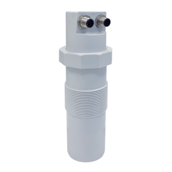
RPL81 - product 2- PRODUCT “1” version “2” version “3” version 1. Skintop M16 2. Head fixing bolt 3. Fixing bolt 4. Watertight connector M12 5. Sensor 6. 5m integrated cables IDENTIFICATION Each meter has an adhesive identifi cation plate on which are indicated the meter main data. The following picture describes the information on the identifi cation plate. Mod. RPL81 P.S. 24Vdc S.N. MU0081604506 1. Product code 2. Power supply 3. -
Page 5: 3-Performance Specifications
RPL81 - features 3-FEATURES Housing/sensor material Mechanical installation 2” GAS M (Flange in PP DN80 (opt.) Protection degree IP67/IP68 (Sensor) - IP68 (opt.) Electrical connection Terminals, connector or 5m integrated cables (IP68) Working temperature -20 ÷ +60°C Pressure from 0,5 to 1,5 bar (absolute) -
Page 6: 4-Dimensions
RPL81 - dimensions 4-DIMENSIONS 5.1 MECHANICAL DIMENSIONS Ch.68 N° 2 FIXING BOLT 2" 2" G Ø55,5 DN80 PN6 UNI 1092-1 flange in PP (Opt.) 2" GAS Page 6 of 40 www.sgm-lektra.com... -
Page 7: 5-Installation
RPL81 - installation 5-INSTALLATION 5.1 MOUNTING PRECAUTIONS 5.1.1 Mounting position - Leave a 300mm (d) minimum distance between the sensor and the tank smooth wall. - Use a protective cover to protect the sensor from weather and direct sunlight (c). - Page 8 In case of nozzle installation, make sure the sensor bottom protrudes at least 10mm from the bottom of the nozzle. Max 90mm. ≥10mm. 5.1.5 Installation with bracket (mod. 835B026Z) By installing the RPL81 with the bracket it is possible to orient the emission lobe perpendicular to inclined surfaces Page 8 of 40 www.sgm-lektra.com...
- Page 9 RPL81 - installation 5.1.6 Agitators presence The level measurement is possible thanks to the Auto-Tuned statistical filter. Should rarely need to adjust the filter setting by editing 2 RPL81 sensor programming parameters: - FILTER; this parameter is present in the Quick Setup menu and in the Advanced Configuration “SETUP” menu; increasing the parameter value, decreases the sensor sensitivity to the level measurement sudden variations. - F-WINDOW; this parameter is present in the Advanced Configuration “SERVICE” menu; decreasing the parameter programmed value, increases the sensor immunity to false echoes. Page 9 of 40 www.sgm-lektra.eu...
-
Page 10: 6-Electrical Connections
RPL81 - electrical connections 6-ELECTRICAL CONNECTIONS 6.1 “1” VERSION CONNECTIONS 1) Separate the engine control cables or power cables from the RPL81 connection cables 2) Open the cap by unscrewing. 3) Lead the cables into the transmitter through the glands 4) Close the cap and tighten the cable glands 4÷20mA... - Page 11 RPL81 - electrical connections 6.3 “3” VERSION CONNECTIONS POWER - RED CABLE SIGNAL - BLACK CABLE BROWN BROWN N / 0V GND DISPLAY L / +24V +3,3V DISPLAY YELLOW YELLOW C RL1 + 4/20mA WITHE WITHE N.O. RL1 SCL DISPLAY...
-
Page 12: 7-Configuration Modes
3) MODBUS RTU communication S/W, cod.010F105A, for RPL81 transmitter With this software is possible: - to connect the RPL81 transmitters in MODBUS RTU network by selecting the UID address - to read on your PC monitor all measures in reading and RPL81 operation data... - Page 13 MODBUS REGISTERS FOR RPL81 Address Address (N°of Type Description (dec) (hex) registers) Distance unsigned int Level unsigned int float Level % Analog output float Distance 4mA unsigned int unsigned int Distance 20mA DAC 4mA unsigned int DAC 20mA unsigned int...
- Page 14 MODBUS REGISTERS FOR RPL81 Measure Note unit Baud rate 9600bps 8data bit 2stop bit no parity no HW flowcontrol 0:MAX 1:MIN 0:Norm_disexcited 1:Norm_excited 0:disabled 1:enabled 0:MAX 1:MIN 0:Norm_disexcited 1:Norm_excited 0:disabled 1:enabled 0:EMPTYING 1:FILLING 0:disabled 1:enabled 0:disabled 1:enabled 0…32767 4:21.5mA 6:38.5mA 8:HoldLastValue 0: off 1:on 0: off 1:on 0: filters disabled 0:NoParity 1:Even 2:Odd 0:9600 1:19200 Page 14 of 40 www.sgm-lektra.com...
- Page 15 The distance has been saved and automatically associated with the RL1 threshold (see default level alarm threshold settings on page 21) 7.2.3 RL2 MIN LEVEL THRESHOLD DISTANCE To set the RL2 maximum level alarm threshold is necessary that the real level is the one corresponding to the “RL2 min. lev. threshold distance”; alternatively it is possible to place a target orthogonally to the RPL81 transmitter at a distance equivalent. Wait until the ECO LED flashes for at least 30s, press simultaneously P1 and P2, release them and verify that the ECO LED remains turned on. Press P1 and then P2 and wait for the ECO LED flashes.
- Page 16 RPL81 - configuration modes 7.3 CALIBRATION / CONFIGURATION VIA VL620/VL621 The VL620/VL621 programming module can be mounted and removed from the RPL81 without affecting the unit operation. Unscrewing the cap (“1” vers.), the VL620 module can be connected or disconnected. For “2” version connect the VL621 module directly to the unit. The VL620/VL621 module are equipped with matrix LCD. N:B: When the VL620/VL621 is connected the communication via MODBUS is inhibited.
-
Page 17: 8-Operator Interface
Displayed at the bottom indicates the correct echo signal reception Displayed at the top alerts that there is a generic error; press SCROLL to show the message that indicates the present error type. The RPL81 returns automatically to RUN mode. QUICK SETUP - Menu with easy access for quick basic parameters configuration. To access: from “RUN” mode press ENTER to the quick setup menu mode access, LEFT ARROW to exit. -
Page 18: 9-Quick Setup
RPL81 - quick setup 9-QUICK SETUP 9.1 - Quick Setup menu structure Parameter Default Values Set Distance 4mA 10000mm 0000 mm Set Distance 20mA 500mm 0000 mm Set Distance 4mA Max Distance 00000mm Set Distance 20mA 00000mm Max Distance Filter Coefficient Filter Coefficient... - Page 19 RPL81 - quick setup 9.2.1 SET DISTANCE 4mA ► SET DISTANCE 4mA SET DISTANCE 20mA MAX DISTANCE Press ENTER to display the distance value associated with 4mA output. FILTER COEFFICENT BLIND DISTANCE DISPLAY RL1 THRESHOLD RL2 THRESHOLD SET DISTANCE 4mA Use SCROLL and UP ARROW to modify that value; in the example the...
- Page 20 RPL81 - quick setup 9.2.3 MAX DISTANCE SET DISTANCE 4mA SET DISTANCE 20mA ► MAX DISTANCE Press the ENTER key to display the previously set maximum distance value. FILTER COEFFICENT The MAX DISTANCE is used to prevent the sensor from detecting an echo signal BLIND DISTANCE at a distance . DISPLAY RL1 THRESHOLD Use SCROLL and UP ARROW to modify the value; in the example, the maximum RL2 THRESHOLD measurement distance is 3600mm. MAX DISTANCE The function is disabled with the value set to 00000mm.
- Page 21 RPL81 - quick setup 9.2.4 FILTER COEFFICIENT SET DISTANCE 4mA SET DISTANCE 20mA MAX DISTANCE Press ENTER. ► FILTER COEFFICENT Use SCROLL and UP ARROW to modify the value. BLIND DISTANCE Input a value from 1 to 99. DISPLAY 1 maximum speed, 99 maximum slowness.
- Page 22 RPL81 - quick setup 9.2.5 BLIND DISTANCE SET DISTANCE 4mA SET DISTANCE 20mA MAX DISTANCE Press ENTER. FILTER COEFFICENT The BLIND ZONE is used to avoid undesired measures near the transmitter. ► BLIND DISTANCE DISPLAY RL1 THRESHOLD RL2 THRESHOLD Use SCROLL and UP ARROW to modify the value. Press ENTER to confirm. The BLIND DISTANCE minimum value is 0050mm.
- Page 23 RPL81 - quick setup 9.2.7 RL1 THRESHOLD SET DISTANCE 4mA SET DISTANCE 20mA MAX DISTANCE Press ENTER to display the previous setting. Set the distance from the FILTER COEFFICENT sensor BLIND DISTANCE DISPLAY RL1 THRESHOLD ► RL2 THRESHOLD Use SCROLL and UP ARROW to modify the value; in the example the RL1 max. level threshold distance is 700mm.
- Page 24 RPL81 - quick setup 9.2.8 RL2 THRESHOLD SET DISTANCE 4mA SET DISTANCE 20mA MAX DISTANCE Press ENTER to display the previous setting. Set the distance from the FILTER COEFFICENT sensor BLIND DISTANCE DISPLAY RL1 THRESHOLD ► RL2 THRESHOLD Use SCROLL and UP ARROW to modify the value; in the example the RL2 min. level threshold distance is 3000mm.
- Page 25 RPL81 - advanced configuration 10-ADVANCED CONFIGURATION 10.1 - “SETUP” MENU SET DISTANCE 4mA 0000mm SETUP SET DISTANCE 4mA SET DISTANCE 20mA 0000mm SET DISTANCE 20mA MAX DISTANCE MAX DISTANCE 00000mm FILTER COEFFICIENT VALUE FILTER COEFFICENT 0000mm BLIND DISTANCE BLIND DISTANCE...
-
Page 26: 10-Advanced Setup
RPL81 - advanced configuration 10.2.1 - SET DISTANCE 4mA ► SET DISTANCE 4mA SET DISTANCE 20mA MAX DISTANCE Position the cursor on DISTANCE 4mA, press ENTER to access. FILTER COEFFICIENT BLIND DISTANCE ACTUAL LEV. 4mA ACTUAL LEV. 20mA RELAYS Use UP ARROW and SCROLL to modify the value. - Page 27 RPL81 - advanced configuration 10.2.5 - BLIND DISTANCE SET DISTANCE 4mA SET DISTANCE 20mA MAX DISTANCE Position the cursor on DISTANCE 4mA, press ENTER to access. FILTER COEFFICIENT Represent the “BLIND ZONE” ► BLIND DISTANCE ACTUAL LEV. 4mA ACTUAL LEV. 20mA...
- Page 28 RPL81 - advanced configuration 10.2.8 - RELAYS SET DISTANCE 4mA SET DISTANCE 20mA MAX DISTANCE Position the cursor on RELAYS, press ENTER to access. FILTER COEFFICIENT BLIND DISTANCE ACTUAL LEV. 4mA ACTUAL LEV. 20mA ► RELAYS In this sub-menù it’s possible to setup onboard relays RL1 can be set as threshold relay or pump-control relay;...
- Page 29 RPL81 - advanced configuration 10.2.8.1.3 - DELAY VALUE MIN/MAX Position the cursor on DELAY, press ENTER to access. ► DELAY SAFETY ANABLE/DISABLE MIN/MAX HYSTERESIS It’s possible to set the activation delay for the selected relay, from 0 to 99 sec. DELAY Use UP ARROW and SCROLL to modify the value.
- Page 30 RPL81 - advanced configuration 10.2.8.2 - RL1 PUMP (only for RL1) RL1 THRESHOLD Position the cursor on RL1 PUMP, press ENTER to access RL2 THRESHOLD ► RL1 PUMP A pump control functioning activation, with hysteresis, is possible two thresh- olds setting is required: ►...
- Page 31 RPL81 - advanced configuration 10.2.8.2.3 - DELAY UPPER Position the cursor on DELAY, press ENTER to access. LOWER ► DELAY FILL./EMPT. ENABLE/DISABLE Set the relay delay activation, from 0 to 99 sec. Use UP ARROW and SCROLL to modify the value.
- Page 32 RPL81 - advanced configuration 10.3 “DISPLAY” menu DISTANCE mm >1 VALUE DISPLAY DISPLAY VALUES LEVEL mm 2 VALUES LEVEL % OUTPUT mA 1 VALUE >2 VALUES >PRIMARY VALUE DISTANCE mm SECONDARY VALUE LCD CONTRAST LIVEL mm LCD CONTRAST LIVEL %...
- Page 33 RPL81 - advanced configuration 10.4.1.2 - 2 VALUE Position the cursor on 2 VALUE, press ENTER to access. 1 VALUE ► 2 VALUES Two values are displayed; it’s possible to choose which one is the primary and which is the secondary, each with a choice of 4 parameters. With the SCROLL button you can select data to display.
- Page 34 RPL81 - advanced configuration 10.5 “DIAGNOSTIC” menu NO ECHO FOUND DISABLE ECHO IN BLIND DIAGNOSTIC ALARM CONFIGURATION >ENABLE DISTANCE >120% MEASURE STATUS PEAK VALUES >DISPLAY VALUES Max 0000mm PEAK VALUES RESET VALUES Min 0000mm OUTPUT SIMUL OUTPUT SIMUL 00.0mA 10.6 - DIAGNOSTIC...
- Page 35 RPL81 - advanced configuration 10.6.2 - MEASURE STATUS ALARM CONFIGURATION ► MEASURE STATUS Position the cursor on MEASURE STATUS, press ENTER to access. PEAK VALUES OUTPUT SIMUL. It’s possible to display a value proportional to the goodness of the MEASURE STATUS installation. During installation search for the maximum value. LEFT ARROW to exit G: 00000 10.6.3 - PEAK VALUES ALARM CONFIGURATION MEASURE STATUS Position the cursor on PEAK VALUES, press ENTER to access.
- Page 36 RPL81 - advanced configuration 10.7 “SERVICE” menu 21.5 mA 3.85 mA SERVICE OUTPUT SAFE MODE >HOLD LAST VALUE SET UID SET UID ENGLISH >ITALIANO LANGUAGE FRANCAIS F_WINDOW F_WINDOW RESTORE SETTINGS OK TO CONFIRM BLUETOOTH CANGE DEVICE PIN RESET MODULE 10.8 - SERVICE...
- Page 37 Example: F_WINDOW parameter set to 5. SET WIDTH - The RPL81 detects an echo signal which is 4 meters from the sensor. - Suddenly, the echo signal disappears and a new echo signal to 3.5 mt away from the sensor is detected. - Each time the echo signal will be emitted, the RPL81 will enlarge “F_WINDOW” with 5cm step, until covering the new eco detected area.
- Page 38 Position the cursor on SET UID, press ENTER to access. LANGUAGE F_WINDOW ► RESTORE SETTING BLUETOOTH Press ENTER to restore the RPL81 default settings LEFT ARROW to exit without restored the RPL81 default settings OK TO CONFIRM 10.8.6 - BLUETOOTH (OPTIONAL) OUTPUT SAFE MODE SET UID Position the cursor on BLUETHOOT, press ENTER to access...
- Page 39 10.9 “INFO” menu SGM-LEKTRA RPL81 INFO FIRMWARE REV. 10.9.1 - INFO SETUP DISPLAY Position the cursor on INFO, press ENTER to access. DIAGNOSTIC SERVICE ► INFO SGM-LEKTRA In addition to information about the manufacturer, are displayed the RPL81 firmware revision and the configuration index FIRMWARE REV.
-
Page 40: 11-Factory Test And Quality Certificate
Documentation subject to technical change with no prior warning 11-FACTORY TEST AND QUALITY CERTIFICATE In conformity to the company and check procedures I certify that the equipment: (Radar level transmitter) is conform to the technical requirements on Technical Data and it is made in conformity to the procedure Quality Control Manager: ............ Production and check date: ..........SGM-LEKTRA S.r.l. Via Papa Giovanni XXIII, 49 20090 Rodano (MI) - ITALY tel: ++39 02 95328257 fax: ++39 02 95328321...
Need help?
Do you have a question about the RPL81 and is the answer not in the manual?
Questions and answers