Advertisement
Quick Links
Advertisement

Subscribe to Our Youtube Channel
Related Manuals for SGM LEKTRA FLOWMETER


Summary of Contents for SGM LEKTRA FLOWMETER
- Page 1 FLOWMETER ultrasonic fl ow transmitter technical documentation EN Rev. F...
- Page 2 FLOWMETER - contents CONTENTS pag. 3 1-WARRANTY pag. 4 2-PRODUCT pag. 5 3-PERFORMANCE SPECIFICATIONS pag. 6 4-DIMENSIONS pag. 7 5-INSTALLATION pag. 9 6-ELECTRICAL CONNECTIONS pag. 11 7-LOCAL OPERATOR INTERFACE (LOI)-VL601 pag. 14 8-SETUP pag. 36 10-FACTORY TEST AND QUALITY CERTIFICATE...
- Page 3 FLOWMETER - warranty 1-WARRANTY Products supplied by SGM LEKTRA are guaranteed for a period of 12 (twelve) months from delivery date accord- ing to the conditions specified in our sale conditions document. SGM LEKTRA can choose to repair or replace the Product.
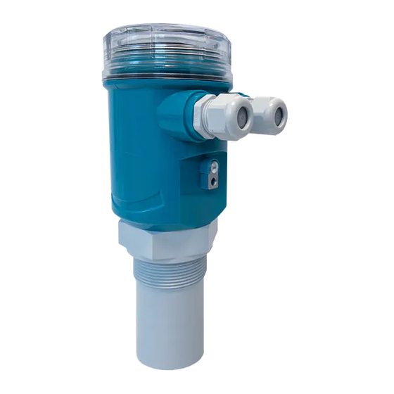
- Page 4 FLOWMETER - features 2- PRODUCT 1. Anticondensation fi lter 2. M20 skintop 3. VL601 (opt.) 4. Sensor IDENTIFICATION Each meter has an adhesive identifi cation plate on which are the meter main data. The following picture describes the information and data on the identifi cation plate.
- Page 5 FLOWMETER - features 3-FEATURES Housing/sensor material PC or Al / PP or PVDF wetted part Mechanical installation 2” GAS M (PP fl ange DN80 opt.) Protection degree IP67/IP68 (Sensor) Electrical connection Internal push connectors Working temperature -20 ÷ +60°C Pressure...
- Page 6 FLOWMETER - dimensions 4-DIMENSIONS 4.1 MECHANICAL DIMENSIONS Page 6 of 36...
- Page 7 10° FLOWMETER 5mt Make sure that the FLOWMETER distance from the weir channel point is equal or greater than to the minimum allowed distance. In the following fi gure, the example with a Venturi channel (min. dist.4xb0) and a Palmer-Bowlus channel (min. dist. D/2) prefabricated (available in our catalog)..
- Page 8 FLOWMETER - installation 5.1.2 Blind distance During installation is important to remember that in the sensor vicinity there is a blind zone (or BLIND DISTANCE) of 0.25m where the sensor can not measure. 0.25mt (5mt) Blind Distance Page 8 of 36...
- Page 9 FLOWMETER - electrical connections 6-ELECTRICAL CONNECTIONS 6.1 WIRING 1) Separate the engine control cables or power cables from the FLOWMETER connection cables 2) Open the cap by unscrewing. 3) Lead the cables into the transmitter through the glands 4) Do not use sleeves terminals, because they might interfere with the VL601 module insertion...
- Page 10 - read on your PC monitor all measures in reading and FLOWMETER operation data - programming all FLOWMETER confi guration parameters - storing on fi les, data logger function; FLOWMETER measures in reading and operating states USB/RS485 Page 10 of 36...
- Page 11 FLOWMETER - local operator interface (LOI) - VL601 7-LOCAL OPERATOR INTERFACE (LOI) - VL601 LOI is an operator communications center for the FLOWMETER. Through the LOI, the operator can access any transmitter function for changing confi guration parameter settings or other functions.
- Page 12 FLOWMETER - local operator interface (LOI) - VL601 The VL601 programming module can be mounted and removed from the FLOWMETER without affecting the unit oper- ation. Unscrewing the cap, the VL601 module can be mounted (by clockwise rotation until it clicks) or dismounted (by rotation counterclockwise) as shown in fi...
- Page 13 FLOWMETER - local operator interface (LOI) - VL601 7.2 - ECHO MAP Pressing LEFT ARROW, from RUN mode, to access directly to the echoes digital map display, which are in FLOWMETER receiving. This function is useful for: properly orient the transducer pointing.
- Page 14 FLOWMETER - confi guration 8-CONFIGURATION 8.1 - “SETUP” menu RL1 COUNTER RL1 COUNTER 00000.00 m3 VALUE 00000.00 m3/h VALUE > MAX >MIN MIN/MAX DELAY SETUP RELAYS RL2 THRESHOLD DELAY SAFETY > > > > ENABLE/DISABLE > >DISABLE ENABLE RL2 DIAGNOSTIC >...
- Page 15 FLOWMETER - confi guration 8.2.1 - RELAY RELAYS Position the cursor on RELAY, press ENTER to confi rm SET MAX FLOW FILTER COEFFICIENT BLIND DISTANCE In this sub-menu it’s possible to setup the on-board relays RL1 can be set as volume pulse output relay;...
- Page 16 FLOWMETER - confi guration 8.2.3.2 - MIN/MAX VALUE MIN / MAX Position the cursor on MIN/MAX, press ENTER to confi rm DELAY SAFETY ENABLE / DISABLE It’s possible to select if the relay works as minimum fl ow rate or maximum fl ow rate threshold.
- Page 17 Position the cursor on RL2 DIAGNOSTIC, press ENTER to confi rm RL1 COUNTER RL2 THRESHOLD If it becomes necessary the FLOWMETER functional control, it’s possible RL2 DIAGNOSTIC to enable the RL2 alarm output function. In this case, enabling the func-...
- Page 18 FLOWMETER - confi guration 8.2.6 - BLIND DISTANCE RELAYS Position the cursor on BLIND DISTANCE, ENTER to confi rm SET MAX FLOW FILTER COEFFICIENT BLIND DISTANCE Represent the “BLIND ZONE” of the sensor. Input the desired value in order to avoid measures near the surface of the sensor (if necessary).
- Page 19 FLOWMETER - confi guration 8.3 - DISPLAY MENU >PRIMARY VALUE DISTANCE mm >SECONDARY VALUE HEAD mm DISPLAY DISPLAY VALUES FLOW TOTALIZER PRIMARY VALUE TEMPERATURE °C > SECONDARY VALUE > > > l/sec l/min SET FLOWRATE /sec /min LCD CONTRAST LCD CONTRAST...
- Page 20 LCD CONTRAST WELCOME TEXT It’s possible to edit or delete the message that is displayed by the FLOWMETER during the ignition phase. WELCOME TEXT Use UP ARROW (up scroll) and SCROLL (down scroll) to change the digit; ENTER to move the digit to the right. To confi rm press ENTER repeatedly SGM-LEKTRA until leave the parameter.
- Page 21 FLOWMETER - confi guration 8.5 FLOW APPL. menu RECT. SUPPRESSED 0000 mm RECT. CONTRACTED FLOW APPL. WEIRS PRIMARY DEVICE TRAPEZOIDAL 0000 DEG V NOTCH BS150 BS200 BS300 BS400 BS500 SGM VENTURI STD BS600 BS800 BS1000 SGM VENTURI CUSTOM SGM VENTURI CUSTOM...
- Page 22 FLOWMETER - confi guration 8.6 - FLOW APPL. SETUP DISPLAY FLOW APPL. SERVICE Press SCROLL to select the menu and press ENTER to access. INFO Press LEFT ARROW to exit. 8.6.1 - PRIMARY DEVICE PRIMARY DEVICE SELF CALIBRATION Position the cursor on primary device, press ENTER to access.
- Page 23 FLOWMETER - confi guration 8.6.1.1.2 - RECT. CONTRACTED Position the cursor on RECT. CONTRACTED (or constriction RECT. SUPPRESSED RECT. CONTRACTED rectangular), ENTER to confi rm TRAPEZOIDAL V NOTCH To set it, simply insert the “L” size. RECT. CONTRACTED Use UP ARROW and SCROLL to modify the value.
- Page 24 FLOWMETER - confi guration 8.6.1.1.4 - V NOTCH Position the cursor on V NOTCH (or triangular), ENTER to confi rm RECT. SUPPRESSED RECT. CONTRACTED TRAPEZOIDAL V NOTCH To set it, simply insert the “L” size. V NOTCH Use UP ARROW and SCROLL to modify the value.
- Page 25 Position the cursor on SGM VENTURI STD, press ENTER to confi rm. KHAFAGI VENTURI “SGM VENTURI STD” are prefabricated Venturi channels and are PARSHALL INCH designed by SGM LEKTRA in collaboration with the Pavia University PARSHALL FEET PALMER BOWLUS PALMER BOWLUS 2 To set it, simply select the Venturi channel model, identifi...
- Page 26 FLOWMETER - confi guration 8.6.1.2.3 - KHAFAGI VENTURI SGM VENTURI STD SGM VENTURI CUSTOM Position the cursor on KHAFAGI VENTURI, press ENTER to confi rm KHAFAGI VENTURI PARSHALL INCH PARSHALL FEET PALMER BOWLUS PALMER BOWLUS 2 QV302 120mm To set it, simply select the “L” size.
- Page 27 FLOWMETER - confi guration 8.6.1.2.5 - PARSHALL FEET SGM VENTURI STD SGM VENTURI CUSTOM Position the cursor on PARSHALL FEET, press ENTER to confi rm. KHAFAGI VENTURI PARSHALL FEET are the Parshall channels with the “L” dimension in PARSHALL INCH feet.
- Page 28 FLOWMETER - confi guration 8.6.1.3 - TABLE Position the cursor on TABLE, press ENTER to confi rm. WEIRS FLUMES The table setting is available only with the MUDBUS communication TABLE software (code 010F119A) CUSTOM 8.6.1.4 - CUSTOM Position the cursor on Custom, press ENTER to confi rm.
- Page 29 FLOWMETER - confi guration WARNING - Proper programming of this parameter is essential for correct fl ow measurement. Do not proceed without having carefully read the below described instructions 8.6.2 - SELF CALIBRATION PRIMARY DEVICE SELF CALIBRATION Position the cursor on self calibration, press ENTER to confi rm.
- Page 30 FLOWMETER - confi guration 8.6.3 - MEASURE STATUS PRIMARY DEVICE SELF CALIBRATION Position the cursor on MEASURE STATUS, press ENTER to confi rm MEASURE STATUS FROZEN GAIN MAX GAIN TH PEAK VALUE START TOTALIZER ALARM CONFIGURATION It’s possible to display the gain of the system, with values from 0 to 255.
- Page 31 DISPLAY VALUE RESET VALURE Displays the max. and min. distance measured from power on. PEAK VALUE m³/h LEFT ARROW to exit. NB - The peak values stored are erased every time the FLOWMETER MAX FLOW 000124.00 turns-off MIN FLOW 000002.00 8.6.6.2 - RESET VALUES...
- Page 32 FLOWMETER - confi guration 8.7 SERVICE menu 21.5 mA 3.85 mA SERVICE OUTPUT SAFE MODE HOLD LAST VALUE SET UID SET UID ENGLISH ITALIANO LANGUAGE FRANCAIS OUTPUT OUTPUT SIMUL. 00.0 mA F_WINDOW F_WINDOW RESTORE SETTINGS OK TO CONFIRM 8.8 - SERVICE...
- Page 33 F_WINDOW are deemed valid. F_WINDOW Example: F_WINDOW parameter set to 5. - The FLOWMETER detects an echo signal which is 4 meters from the sensor. - Suddenly, the echo signal disappears and a new echo signal to 3.5 mt away from the sensor is detected.
- Page 34 Position the cursor on SET UID, press ENTER to access. LANGUAGE OUTPUT SIMULATION F. WINDOW RESTORE SETTING Press ENTER to restore the FLOWMETER default settings LEFT ARROW to exit without restored the FLOWMETER default settings OK TO CONFIRM 8.9 INFO MENU SGM-LEKTRA METER INFO FIRMWARE REV.
- Page 35 Page 35 of 36...
- Page 36 Documentation subject to technical change with no prior warning 9-FACTORY TEST AND QUALITY CERTIFICATE In conformity to the company and check procedures I certify that the equipment: (Ultrasonic sensor) is conform to the technical requirements on Technical Data and it is made in conformity to the procedure Quality Control Manager: ............
Need help?
Do you have a question about the FLOWMETER and is the answer not in the manual?
Questions and answers