Juniper M7i Hardware Manual
Multiservice edge router
Hide thumbs
Also See for M7i:
- Hardware manual (232 pages) ,
- Quick start manual (23 pages) ,
- Manual (2 pages)

Related Manuals for Juniper M7i


Summary of Contents for Juniper M7i
- Page 1 M7i Multiservice Edge Router Hardware Guide Modified: 2019-01-04 Copyright © 2019, Juniper Networks, Inc.
- Page 2 END USER LICENSE AGREEMENT The Juniper Networks product that is the subject of this technical documentation consists of (or is intended for use with) Juniper Networks software. Use of such software is subject to the terms and conditions of the End User License Agreement (“EULA”) posted at https://support.juniper.net/support/eula/.
-
Page 3: Table Of Contents
Outstanding Issues with the M7i Router ........ - Page 4 M7i Flexible PIC Concentrators (FPCs) Description ......43 M7i Fixed Interface Card (FIC) Description ....... 44 FIC Specifications for the M7i Router .
- Page 5 M7i Router Site Preparation Checklist ........
- Page 6 Verifying the M7i Router Parts Received ....... . . 107...
- Page 7 Installing an SFP into an M7i Router ....... . 167...
- Page 8 Maintaining the M7i CFEB and CFEB-E ....... . . 195...
- Page 9 M7i Laser and LED Safety Warnings ........
- Page 10 M7i AC Power Electrical Safety Guidelines and Warnings ....254 M7i DC Power Electrical Safety Guidelines ......255 DC Power Electrical Safety Warnings for Juniper Networks Devices .
- Page 11 Figure 23: Typical Open-Frame Rack ........76 Copyright © 2019, Juniper Networks, Inc.
- Page 12 Chapter 18 Connecting the M7i to External Devices ......115 Figure 31: Routing Engine Ethernet Cable Connector ..... . 116 Figure 32: Routing Engine Interface Ports .
- Page 13 Electrical Safety Guidelines and Warnings ......249 Figure 74: Placing a Component into an Electrostatic Bag ....250 Copyright © 2019, Juniper Networks, Inc. xiii...
- Page 14 M7i Multiservice Edge Router Hardware Guide Copyright © 2019, Juniper Networks, Inc.
- Page 15 Table 7: M7i Routing Engines ........
- Page 16 Table 35: FIC Interface LEDs ......... . 46 Table 36: PICs Supported in the M7i Router ......48 Table 37: End-of-Life PICs Supported in the M7i Router .
- Page 17 Table 59: Chassis Alarm Messages ........200 Table 60: SONET/SDH Interface Alarm Messages ......203 Copyright © 2019, Juniper Networks, Inc. xvii...
- Page 18 M7i Multiservice Edge Router Hardware Guide xviii Copyright © 2019, Juniper Networks, Inc.
-
Page 19: About The Documentation
® To obtain the most current version of all Juniper Networks technical documentation, see the product documentation page on the Juniper Networks website at https://www.juniper.net/documentation/ If the information in the latest release notes differs from the information in the documentation, follow the product Release Notes. -
Page 20: Table 1: Notice Icons
M7i Multiservice Edge Router Hardware Guide Table 1: Notice Icons Icon Meaning Description Informational note Indicates important features or instructions. Caution Indicates a situation that might result in loss of data or hardware damage. Warning Alerts you to the risk of personal injury or death. -
Page 21: Documentation Feedback
We encourage you to provide feedback so that we can improve our documentation. You can use either of the following methods: Online feedback system—Click TechLibrary Feedback, on the lower right of any page on the Juniper Networks TechLibrary site, and do one of the following: Copyright © 2019, Juniper Networks, Inc. -
Page 22: Requesting Technical Support
7 days a week, 365 days a year. Self-Help Online Tools and Resources For quick and easy problem resolution, Juniper Networks has designed an online self-service portal called the Customer Support Center (CSC) that provides you with the following features: Find CSC offerings: https://www.juniper.net/customers/support/... -
Page 23: Creating A Service Request With Jtac
About the Documentation Join and participate in the Juniper Networks Community Forum: https://www.juniper.net/company/communities/ Create a service request online: https://myjuniper.juniper.net To verify service entitlement by product serial number, use our Serial Number Entitlement (SNE) Tool: https://entitlementsearch.juniper.net/entitlementsearch/ Creating a Service Request with JTAC You can create a service request with JTAC on the Web or by telephone. - Page 24 M7i Multiservice Edge Router Hardware Guide xxiv Copyright © 2019, Juniper Networks, Inc.
-
Page 25: Overview
PART 1 Overview System Overview and Architecture on page 3 M7i Router Release Notes on page 9 Chassis Components and Descriptions on page 11 Cooling System Components and Descriptions on page 15 Host Subsystem Components and Description on page 17... - Page 26 M7i Multiservice Edge Router Hardware Guide Copyright © 2019, Juniper Networks, Inc.
-
Page 27: System Overview And Architecture
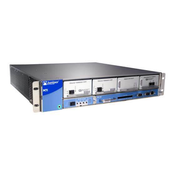
Routing Engine Architecture on page 6 M7i Router Description The M7i Multiservice Edge Router is a complete routing system that provides ATM, channelized, Ethernet, IP services, and SONET/SDH interfaces for large networks and network applications, such as those supported by Internet service providers (ISPs). -
Page 28: M7I Component Redundancy
Documentation M7i Chassis Description on page 11 M7i Router Physical Specifications on page 74 Overview of M7i Router Installation on page 103 M7i Component Redundancy The router can be configured with two load-sharing, fully redundant power supplies to distribute power to the other components. If one power supply fails, the second power supply can provide full power to the router's components indefinitely. -
Page 29: M7I And M10I Packet Forwarding Engine Architecture
Chapter 1: System Overview and Architecture M7i and M10i Packet Forwarding Engine Architecture The Packet Forwarding Engine performs Layer 2 and Layer 3 packet switching. The Packet Forwarding Engine is implemented in application-specific integrated circuits (ASICs). It uses a centralized route lookup engine and shared memory. -
Page 30: Routing Engine Architecture
M7i Router Description on page 3 Routing Engine Architecture The Routing Engine runs the Junos OS, which Juniper Networks has developed and optimized to handle large numbers of network interfaces and routes. The software consists of a set of system processes running in protected memory modules on top of an independent operating system. -
Page 31: Routing Engine Functions
Monitoring efficiency and flexibility—The router supports functions such as alarm handling and packet counting on every port, without degrading packet-forwarding performance. Copyright © 2019, Juniper Networks, Inc. -
Page 32: Figure 4: Control Packet Handling For Routing And Forwarding Table
Figure 4: Control Packet Handling for Routing and Forwarding Table Updates Related M7i Routing Engine Description on page 17 Documentation Maintaining the M7i Routing Engine on page 192 Replacing the M7i Routing Engine on page 141 Copyright © 2019, Juniper Networks, Inc. -
Page 33: M7I Router Release Notes
There are two versions of the Compact Forwarding Engine Board (CFEB) for M7i routers: CFEB with 4 megabytes (MB) of I/O Manager SSRAM—When this CFEB is installed on an M7i router, Junos OS Release 6.0R1 or later is required. The part number for this CFEB is 750-009489 or 750-009490. -
Page 34: Errata With The M7I Router Documentation
The M7i router now supports the RE-850-1536 Routing Engine. Related Outstanding Issues with the M7i Router on page 9 Documentation M7i Compact Forwarding Engine Board (CFEB) and Enhanced Compact Forwarding Engine Board (CFEB-E) Description on page 63 Copyright © 2019, Juniper Networks, Inc. -
Page 35: Chassis Components And Descriptions
The router chassis is a rigid sheet metal structure that houses the other hardware components. The chassis is 17.5 in. (44.5 cm) wide and 18 in. (45.7 cm) deep. The chassis height of 3.5 in. (8.9 cm) enables stacked installation of 21 M7i routers in a single floor-to-ceiling rack. For more information, see “M7i Router Rack Requirements”... -
Page 36: M7I Midplane Description
Related M7i Router Physical Specifications on page 74 Documentation Overview of M7i Router Installation on page 103 M7i Router Description on page 3 M7i Midplane Description The midplane is a panel located in the center of the chassis, running from side to side... -
Page 37: M7I Cable Management System
The cable management system evenly distributes the weight of a cable, so that it is not subjected to undue stress at the connector. Related Installing the M7i Cable Management System on page 109 Documentation M7i Router Description on page 3 Overview of M7i Router Installation on page 103 Copyright ©... - Page 38 M7i Multiservice Edge Router Hardware Guide Copyright © 2019, Juniper Networks, Inc.
-
Page 39: Cooling System Components And Descriptions
CHAPTER 4 Cooling System Components and Descriptions M7i Cooling System Overview on page 15 M7i Cooling System Overview The router cooling system consists of a fan tray, located along the left side of the chassis, that provides side-to-side cooling (see Figure 9 on page 16). -
Page 40: Figure 9: Airflow Through The Chassis
Figure 9: Airflow Through the Chassis Related Maintaining the M7i Cooling System on page 191 Documentation M7i Router Clearance Requirements for Airflow and Hardware Maintenance on page 77 M7i Router Description on page 3 Copyright © 2019, Juniper Networks, Inc. -
Page 41: Host Subsystem Components And Description
Description M7i Routing Engine Description on page 17 M7i Routing Engine LEDs on page 20 M7i Routing Engine RE-B-1800 Description on page 20 M7i Routing Engine 1800 LEDs on page 22 Routing Engine Specifications on page 22 Supported Routing Engines by Router on page 27 M7i Routing Engine Description The Routing Engine runs Junos OS. -
Page 42: Boot Sequence
M7i Multiservice Edge Router Hardware Guide Figure 10: Routing Engine The Routing Engine (shown in Figure 10 on page 18) is a two-board system with the following components: CPU—Runs Junos OS to maintain the router's routing tables and routing protocols. It has a Pentium-class processor. -
Page 43: M7I Routing Engine Management Ports
100-Mbps connection. For information about the pinouts for the connectors, see “RJ-45 Connector Pinouts for the M7i Routing Engine MGMT Port” on page Figure 11 on page 19 shows the ports that connect to the Routing Engine. -
Page 44: M7I Routing Engine Leds
State Description Green Blinking There is read/write activity on the PC card. Blue On steadily Routing Engine is functioning as master. On an M7i MASTER router, this LED is always lit. FAIL On steadily Routing Engine is not operational. ONLINE... - Page 45 CompactFlash card, then the SSD, then the LAN. Normally, the router boots from the copy of the software on the CompactFlash card. Related M7i Routing Engine 1800 LEDs on page 22 Documentation Replacing the M7i Routing Engine on page 141 Replacing the SSD on an RE-B-1800 Routing Engine on page 143 Copyright ©...
-
Page 46: M7I Routing Engine 1800 Leds
Green On steadily Routing Engine is running normally. ONLINE Related Displaying M7i Router Components and Serial Numbers on page 213 Documentation M7i Router Physical Specifications on page 74 Routing Engine Specifications Table 5 on page 22 lists the current specifications for Routing Engines supported on M Series, MX Series, and T Series routers. - Page 47 11.4R2 RE-C2600 2.6-GHz 16 GB Gigabit 4 GB TX Matrix Plus – Ethernet CompactFlash router: 9.6R2 card RE-A-1800x2 1800-MHz 8 GB or 16 Gigabit 32 GB SSD 4 GB 10.4 – Ethernet CompactFlash card Copyright © 2019, Juniper Networks, Inc.
- Page 48 M7i Multiservice Edge Router Hardware Guide Table 5: Routing Engine Specifications (continued) Routing Connection First Junos OS Switch Control Engine Processor Memory to PFEs Disk Media Support Board RE-S-1800x2 1800-MHz 8 GB or 16 Gigabit 32 GB SSD 4 GB 10.4...
-
Page 49: Table 6: End-Of-Life Routing Engine Specifications
RE-333-256 333-MHz 256 MB Fast 6.4 GB hard 80 MB PSN-2003-01-063 Pentium II Ethernet disk CompactFlash card RE-333-768 333-MHz 768 MB Fast 6.4 GB hard 80 MB PSN-2003-01-063 Pentium II Ethernet disk CompactFlash card Copyright © 2019, Juniper Networks, Inc. - Page 50 M7i Multiservice Edge Router Hardware Guide Table 6: End-of-Life Routing Engine Specifications (continued) Routing Connection First Junos OS Engine Processor Memory to PFEs Disk Media Support EOL Details RE-600-512 600-MHz 512 MB Fast 30 GB hard 256 MB PSN-2004-07-019 Pentium III...
-
Page 51: Supported Routing Engines By Router
TX Matrix Plus (with 3D SIBs) Routing Engines on page 42 M7i Routing Engines Table 7 on page 28 lists the Routing Engines supported by the M7i router. The M7i router supports 32-bit Junos OS only. Copyright © 2019, Juniper Networks, Inc. -
Page 52: M10I Routing Engines
M7i Multiservice Edge Router Hardware Guide Table 7: M7i Routing Engines Name in CLI First Supported 32-bit Management Internal Ethernet Model Number Output Junos OS Release Ethernet Interface Interface RE-400-768 (EOL details: RE-5.0 fxp0 fxp1 TSB16445 RE-850-1536 (EOL details: fxp0... -
Page 53: M120 Routing Engines
64-bit Junos Ethernet Internal Ethernet Model Number Output Release OS Release Interface Interface RE-1600-2048 (EOL – fxp0 fxp1 RE-4.0 TSB14374 details: fxp2 RE-A-2000-4096 – fxp0 RE-A-2000 bcm0 RE-A-1800X2-8G RE-A-1800x2 11.4R5 10.4 fxp0 12.1R3 bcm0 Copyright © 2019, Juniper Networks, Inc. -
Page 54: Mx5, Mx10, Mx40, And Mx80 Routing Engine
M7i Multiservice Edge Router Hardware Guide Table 11: M320 Routing Engines (continued) First First Supported Supported Management Name in CLI 32-bit Junos OS 64-bit Junos Ethernet Internal Ethernet Model Number Output Release OS Release Interface Interface RE-A-1800X2-16G 11.4R5 10.4 fxp0 RE-A-1800x2 12.1R3... -
Page 55: Mx480 Routing Engines
RE-S-2X00x6 16.1R1 RE-S-X6-64G-LT RE-S-2X00x6 -LT – 17.2R1 fxp0 ixlv0, igb0 RE-S-X6-128G – 18.1R1 fxp0 ixlv0, igb0 RE-S-2X00x6-128 MX480 Routing Engines Table 15 on page 32 lists the Routing Engines supported by MX480 routers. Copyright © 2019, Juniper Networks, Inc. -
Page 56: Mx960 Routing Engines
M7i Multiservice Edge Router Hardware Guide Table 15: MX480 Supported Routing Engines First Supported First Supported Management Name in CLI 32-bit Junos OS 64-bit Junos OS Ethernet Internal Ethernet Model Number Output Release Release Interface Interface RE-S-1300-2048 RE-S-1300 – fxp0... -
Page 57: Mx2008 Routing Engines
RE-S-2X00x6 MX960-VC) RE-S-X6-64G-LT – 17.2R1 fxp0 ixlv0, igb0 RE-S-2X00x6 -LT RE-S-X6-128G RE-S-2X00x6-128 – 18.1R1 fxp0 ixlv0, igb0 MX2008 Routing Engines Table 17 on page 34 lists the Routing Engines supported by MX2008 routers. Copyright © 2019, Juniper Networks, Inc. -
Page 58: Mx2010 Routing Engines
M7i Multiservice Edge Router Hardware Guide Table 17: MX2008 Supported Routing Engines Management Internal Name in CLI First Supported 64-bit Junos Ethernet Ethernet Model Number Output OS Release Interface Interface REMX2008-X8-64G RE-MX2008-X8-64G 15.1F7 fxp0 ixlv0 ixlv1 REMX2008-X8-64G-LT 17.2R1 fxp0 ixlv0... -
Page 59: Mx10003 Routing Engines
Ethernet Ethernet Model Number Output OS Release Interface Interface JNP10003-RE1 17.3R1 fxp0 RE-S-2X00x6 JNP10003-RE1-LT RE-S-1600x8 18.1R1 fxp0 MX10008 Routing Engines Table 21 on page 36 lists the Routing Engines supported on the MX10008 router. Copyright © 2019, Juniper Networks, Inc. -
Page 60: Ptx1000 Routing Engines
M7i Multiservice Edge Router Hardware Guide Table 21: MX10008 Routing Engines First Supported Management Internal Ethernet Model Number Name in CLI Output Junos OS Release Ethernet Interface Interface JNP10K-RE1 RE X10 18.2R1 bme0 bme1 JNP10K-RE1-LT RE X10 LT 18.3R1 bme0... -
Page 61: Ptx5000 Routing Engines
Release Interface Interface RE-DUO-C2600-16G 12.1X48 ixgbe0 RE-DUO-2600 12.3 ixgbe1 13.2 NOTE: The PTX5000 does not support Junos OS Releases 12.1, 12.2, or 13.1. RE-PTX-X8-64G 15.1F4 ixlv0 RE-PTX-2X00x8 16.1R1 ixlv1 RE-PTX-X8-128G RE-PTX-2X00x8-128G 18.1R1 ixlv0 ixlv1 Copyright © 2019, Juniper Networks, Inc. -
Page 62: Ptx10008 And Ptx10016 Routing Engines
M7i Multiservice Edge Router Hardware Guide PTX10008 and PTX10016 Routing Engines Table 25 on page 38 lists the Routing Engines supported on the PTX10008 and PTX10016 routers. Table 25: PTX10008 and PTX10016 Routing Engines First Supported Management Internal Ethernet Model Number... -
Page 63: T1600 Routing Engines
First Supported Management Internal Name in CLI First Supported 32-bit 64-bit Junos OS Ethernet Ethernet Model Number Output Junos OS Release Release Interface Interface RE-600-2048 (EOL – fxp0 fxp1 RE-3.0 TSB14373 details: RE-3.0 fxp2 (RE-600) Copyright © 2019, Juniper Networks, Inc. -
Page 64: T4000 Routing Engines
M7i Multiservice Edge Router Hardware Guide Table 28: T1600 Routing Engines (continued) First Supported Management Internal Name in CLI First Supported 32-bit 64-bit Junos OS Ethernet Ethernet Model Number Output Junos OS Release Release Interface Interface RE-1600-2048 (EOL RE-4.0 –... -
Page 65: Tx Matrix Routing Engines
64-bit Junos OS Ethernet Ethernet Model Number Output Release Release Interface Interface RE-DUO-C2600-16G 32-bit Junos OS: 9.6 64-bit Junos OS: 11.4 ixgbe0 RE-TXP-SFC RE-DUO-2600 ixgbe1 The TX Matrix Plus router supports the CB-TXP control board. Copyright © 2019, Juniper Networks, Inc. -
Page 66: Tx Matrix Plus (With 3D Sibs) Routing Engines
M7i Multiservice Edge Router Hardware Guide TX Matrix Plus (with 3D SIBs) Routing Engines Table 32 on page 42 lists the Routing Engines supported by the TX Matrix Plus router with 3D SIBs. Table 32: Routing Engines on TX Matrix Plus with 3D SIBs... -
Page 67: Line Card Components And Descriptions
46). On the M7i router, each FPC is built in (it cannot be removed from the chassis as on other M Series routers). The networking and services interfaces in the M7i router are grouped onto two logical FPCs by the router, (see Figure 13 on page 43). -
Page 68: M7I Fixed Interface Card (Fic) Description
Figure 14 on page 44 Figure 15 on page For more information about Fast Ethernet and Gigabit Ethernet interfaces, see the M7i Multiservice Edge Router Interface Module Reference. The networking interface on the FIC is configured the same way as a PIC. For more information about configuring interfaces see the Junos OS Network Interfaces Library for Routing Devices. -
Page 69: Fic Specifications For The M7I Router
M7i PICs Description on page 46 Documentation M7i Fixed Interface Card (FIC) Description on page 44 Connecting FIC and PIC Cables to the M7i Router on page 120 M7i FIC LEDs Two large alarm LEDs are located on the right of the FIC (see... -
Page 70: M7I Pics Description
PIC depends on the type of PIC. The M7i router has a maximum throughput of 3.2 Gbps full duplex for the FPC with 4 PIC slots. Inserting a combination of PICs with an aggregate higher than the maximum... -
Page 71: M7I Pic Leds
STATUS on the PIC faceplate. Some PICs have additional LEDs, often one per port. The meaning of the LED states differs for various PICs. For more information, see the M7i Multiservice Edge Router Interface Module Reference. Related M7i PICs Description on page 46... -
Page 72: Table 36: Pics Supported In The M7I Router
M7i Multiservice Edge Router Hardware Guide NOTE: The M7i router is now end-of-life. See the JTAC support bulletin TSB16809 for additional information about the PICs and other associated FRUs that moved to end-of-life with the router. The “M7i End-of-Life PICs Supported”... - Page 73 Chapter 6: Line Card Components and Descriptions Table 36: PICs Supported in the M7i Router (continued) First Junos OS Release PIC Family and Type Ports Model Number Connector Support DS3, E1, E3, and T1 DS3/E3 Enhanced IQ (IQE) PIC PE-4DS3-E3-IQE-BNC Standard DS3 BNC coaxial cable 10.2...
-
Page 74: M7I End-Of-Life Pics Supported
M7i PIC/CFEB Compatibility on page 53 M7i End-of-Life PICs Supported Table 37 on page 50 lists the end-of-life PICs supported by the M7i router. The PICs are listed alphabetically by PIC family. NOTE: The M7i router is now end-of-life. See the JTAC support bulletin TSB16809 for additional information about the PICs and other associated FRUs that moved to end-of-life with the router. - Page 75 Chapter 6: Line Card Components and Descriptions Table 37: End-of-Life PICs Supported in the M7i Router (continued) First Junos OS PIC Family and Type Ports Model Number Release Support ATM2 IQ ATM2 E3 IQ EOL PIC (M7i Router) PE-2E3-ATM2 Channelized...
- Page 76 M7i Multiservice Edge Router Hardware Guide Table 37: End-of-Life PICs Supported in the M7i Router (continued) First Junos OS PIC Family and Type Ports Model Number Release Support Gigabit Ethernet EOL PIC (M7i Router) PE-1GE-LH PE-1GE-LX PE-1GE-SX Ethernet IQ Gigabit Ethernet IQ EOL PIC with SFP (M7i Router)
-
Page 77: M7I Pic Combination Limitations
PIC slots 0 and 1, or in slots 2 and 3. If you have different PIC families in the M7i router and are running Junos OS Release 10.2 or later, review the configuration rules to plan which PICs to install in your router. Consult technical bulletin... - Page 78 M7i Multiservice Edge Router Hardware Guide Table 38: CFEB/PIC Compatibility in the M7i Router (continued) PIC Family and Type Ports PIC Model Number CFEB CFEB-E ATM2 E3 IQ EOL PIC (M7i Router) PE-2E3-ATM2 ATM2 OC3/STM1 IQ PIC (M7i Router) PE-2OC3-ATM2-MM...
- Page 79 Chapter 6: Line Card Components and Descriptions Table 38: CFEB/PIC Compatibility in the M7i Router (continued) PIC Family and Type Ports PIC Model Number CFEB CFEB-E DS3, E1, E3, and T1 DS3 EOL PIC (M7i Router) PE-2DS3 DS3 EOL PIC (M7i Router)
- Page 80 M7i Multiservice Edge Router Hardware Guide Table 38: CFEB/PIC Compatibility in the M7i Router (continued) PIC Family and Type Ports PIC Model Number CFEB CFEB-E Gigabit Ethernet IQ2 EOL PIC with SFP (M7i PE-4GE-TYPE1-SFP-IQ2 7.6R3 Router) Ethernet Enhanced IQ2 (IQ2E)
- Page 81 Chapter 6: Line Card Components and Descriptions Table 38: CFEB/PIC Compatibility in the M7i Router (continued) PIC Family and Type Ports PIC Model Number CFEB CFEB-E SONET/SDH SONET/SDH OC3c/STM1 EOL PIC (M7i PE-2OC3-SON Router) EOL (see notification PSN-2007-12-037 PE-2OC3-SON-MM EOL (see notification...
- Page 82 M7i Multiservice Edge Router Hardware Guide Copyright © 2019, Juniper Networks, Inc.
-
Page 83: Power System Components And Descriptions
Power supplies are hot-removable and hot-insertable, as described in “M7i Field-Replaceable Units (FRUs)” on page 135. To avoid electrical injury, carefully follow the instructions in “Replacing an M7i AC Power Supply” on page 177 “Replacing a DC Power Supply” on page 171. Copyright © 2019, Juniper Networks, Inc. -
Page 84: M7I Ac Power Supply
Documentation M7i DC Power Supply on page 61 Removing an M7i AC Power Supply on page 177 Troubleshooting the M7i Power System When the LED on One M7i Power Supply Is Off on page 206 M7i AC Power Supply An AC-powered router has one or two load-sharing AC power supplies, located at the... -
Page 85: M7I Dc Power Supply
Chapter 7: Power System Components and Descriptions Installing an M7i AC Power Cord on page 181 M7i AC Power Electrical Safety Guidelines and Warnings on page 254 Removing an M7i AC Power Cord on page 181 Replacing an M7i AC Power Supply on page 177... -
Page 86: Table 39: States For The M7I Power Supply Led
M7i Power System Description on page 59 Replacing an M7i AC Power Supply on page 177 Troubleshooting the M7i Power System When the LED on One M7i Power Supply Is Off on page 206 Copyright © 2019, Juniper Networks, Inc. -
Page 87: Switch Fabric Components And Descriptions
M7i Compact Forwarding Engine Board (CFEB) and Enhanced Compact Forwarding Engine Board (CFEB-E) Description The M7i Multiservice Edge Router houses either a Compact Forwarding Engine Board (CFEB) or an Enhanced Compact Forwarding Engine Board (CFEB-E), which is located on the rear of the router above the power supplies, as shown in Figure 6 on page 12. -
Page 88: Cfeb
Services Interfaces Library for Routing Devices. Optional Adaptive Services Module (ASM)—Provides one or more services on one PIC. “M7i Adaptive Services Module” on page 67 for more information. The CFEB and CFEB-E are hot-pluggable when you replace a CFEB with a CFEB or a CFEB-E with a CFEB-E. -
Page 89: Cfeb-E
CFEB-E The CFEB-E provides the following additional and enhanced functions: Optional MultiServices Module (MSM)—Provides one or more services on one PIC. See “M7i MultiServices Module” on page 68 for more information. Increased number of logical interfaces. Increased route, nexthop, and interface lookup memory. - Page 90 M7i Multiservice Edge Router Hardware Guide Hierarchical policing Increased number of WRED profiles Independent EXP and DSCP rewrite Independent Layer 2 and Layer 3 classification on same port The CFEB-E has the following major components: Processing components: 1-GHz CPU and supporting circuitry...
-
Page 91: M7I Adaptive Services Module
Figure 22: CFEB-E with MultiServices Module M7i Adaptive Services Module The Adaptive Services Module is an optional component of the CFEB and CFEB-E. The Adaptive Services Module is similar to the standalone Adaptive Services PIC, but operates Copyright © 2019, Juniper Networks, Inc. -
Page 92: M7I Multiservices Module
M7i Multiservice Edge Router Hardware Guide at a reduced bandwidth. The Adaptive Services Module enables you to perform one or more services on the same PIC by configuring a set of services and applications. The Adaptive Services Module provides the following services: Stateful firewall—A type of firewall filter that considers state information derived from... -
Page 93: M7I Cfeb And Cfeb-E Leds
Interfaces Library for Routing Devices. Related M7i CFEB and CFEB-E LEDs on page 69 Documentation M7i and M10i Packet Forwarding Engine Architecture on page 5 M7i Router Description on page 3 M7i Router Physical Specifications on page 74 M7i CFEB and CFEB-E LEDs... - Page 94 M7i Multiservice Edge Router Hardware Guide Copyright © 2019, Juniper Networks, Inc.
-
Page 95: Site Planning, Preparation, And Specifications
AC Power Requirements and Specifications on page 83 DC Power Requirements and Specifications on page 87 Network Cable and Transceiver Planning on page 91 Management Cable and Transceiver Specifications and Pinouts on page 97 Copyright © 2019, Juniper Networks, Inc. - Page 96 M7i Multiservice Edge Router Hardware Guide Copyright © 2019, Juniper Networks, Inc.
-
Page 97: Preparation Overview
M7i Router Physical Specifications on page 74 M7i Router Rack Requirements on page 75 M7i Router Clearance Requirements for Airflow and Hardware Maintenance on page 77 M7i Router Environmental Specifications on page 78 M7i Chassis Grounding, Connection, and Cable Specifications on page 78... -
Page 98: M7I Router Physical Specifications
M7i Router Description on page 3 Documentation M7i Router Physical Specifications on page 74 M7i Router Clearance Requirements for Airflow and Hardware Maintenance on page 77 M7i Router Physical Specifications Table 42 on page 74 summarizes the physical specifications for the router chassis. -
Page 99: M7I Router Rack Requirements
Cabinets, Racks, Panels, and Associated Equipment (document number EIA-310-D) published by the Electronics Components Industry Association. You can stack 21 M7i routers in a rack that has at least 42 U (73.5 in. or 1.87 m) of usable vertical space. -
Page 100: Figure 23: Typical Open-Frame Rack
Related Installation Safety Warnings for Juniper Networks Devices on page 233 Documentation M7i Router Clearance Requirements for Airflow and Hardware Maintenance on page 77 M7i Router Physical Specifications on page 74 M7i Router Site Preparation Checklist on page 73 Copyright © 2019, Juniper Networks, Inc. -
Page 101: M7I Router Clearance Requirements For Airflow And Hardware Maintenance
Chapter 9: Preparation Overview M7i Router Clearance Requirements for Airflow and Hardware Maintenance When planning the installation site, you need to allow sufficient clearance around the rack (see Figure 24 on page 77): For the cooling system of side-cooled routers to function properly, the airflow around the chassis must be unrestricted. -
Page 102: M7I Router Environmental Specifications
For additional safety guidelines and requirements, see “General Safety Guidelines for Juniper Networks Devices” on page 225. Related M7i Router Physical Specifications on page 74 Documentation M7i Router Power Requirements on page 79 M7i Router Description on page 3 M7i Chassis Grounding, Connection, and Cable Specifications To ground a router, connect a grounding cable to earth ground and then attach it to the chassis grounding point on the rear of the chassis. -
Page 103: M7I Router Power Requirements
Figure 25: Grounding Cable Connection Related M7i Chassis Description on page 11 Documentation Connecting the Grounding Cable to the M7i Router on page 113 M7i Router Power Requirements Table 46 on page 80 lists the power requirements for various hardware components when the router is operating under typical voltage conditions. -
Page 104: Table 46: M7I Component Power Requirements
M7i Multiservice Edge Router Hardware Guide Table 46: M7i Component Power Requirements Power Requirement (Amps)@ 48 Component Base system (cooling system, power supplies, and FIC) 0.6 A CFEB/CFEB-E 1.4 A CFEB/CFEB-E with Adaptive Services Module 1.9 A CFEB-E with MultiServices Module 1.9 A... - Page 105 Related M7i Router AC Power Supply Specifications on page 85 Documentation M7i Router DC Power Supply Specifications on page 87 General Electrical Safety Warnings for Juniper Networks Devices on page 250 Copyright © 2019, Juniper Networks, Inc.
- Page 106 M7i Multiservice Edge Router Hardware Guide Copyright © 2019, Juniper Networks, Inc.
-
Page 107: Ac Power Requirements And Specifications
CHAPTER 10 AC Power Requirements and Specifications M7i Router AC Power, Connection, and Power Cord Specifications on page 83 M7i Router AC Power Supply Specifications on page 85 M7i Router AC Power, Connection, and Power Cord Specifications Detachable AC power cords, each 2.5 m (approximately 8 ft) long, are supplied with the router. -
Page 108: Figure 26: Ac Plug Types
Power cords and cables must not block access to router components or drape where people could trip on them. Related M7i AC Power Supply on page 60 Documentation Connecting Power to an AC-Powered M7i Router on page 123 Copyright © 2019, Juniper Networks, Inc. -
Page 109: M7I Router Ac Power Supply Specifications
Replacing an M7i AC Power Supply on page 177 Replacing an M7i AC Power Cord on page 181 M7i Router Power Requirements on page 79 M7i Router AC Power, Connection, and Power Cord Specifications on page 83 Copyright © 2019, Juniper Networks, Inc. - Page 110 M7i Multiservice Edge Router Hardware Guide Copyright © 2019, Juniper Networks, Inc.
-
Page 111: Dc Power Requirements And Specifications
DC Power Requirements and Specifications M7i Router DC Power Supply Specifications on page 87 M7i DC Power Cable and Cable Lug Specifications on page 88 M7i Router DC Power Supply Specifications Table 49 on page 87 lists electrical specifications for the DC power supply. -
Page 112: M7I Dc Power Cable And Cable Lug Specifications
M7i Multiservice Edge Router Hardware Guide M7i DC Power Cable and Cable Lug Specifications DC Power Cables on page 88 DC Power Lugs on page 89 DC Power Cables To supply power to the router, connect power cables to a separate, dedicated DC power source for each power supply and attach the cables to the field-wiring terminals on each power supply. -
Page 113: Dc Power Lugs
M7i DC Power Supply on page 61 Documentation Replacing a DC Power Supply on page 171 Replacing an M7i DC Power Cable on page 175 M7i Router Power Requirements on page 79 M7i Router DC Power Supply Specifications on page 87... - Page 114 M7i Multiservice Edge Router Hardware Guide Copyright © 2019, Juniper Networks, Inc.
-
Page 115: Network Cable And Transceiver Planning
Attenuation and Dispersion in Fiber-Optic Cable on M Series, MX Series, and T Series Documentation Routers on page 91 Signal Loss in Multimode and Single-Mode Fiber-Optic Cable for the M7i Router on page 92 Calculating Power Budget for Fiber-Optic Cable for M Series, MX Series, and T Series... -
Page 116: Router
Fiber-Optic and Network Cable Specifications for the M7i Router on page 91 Documentation Signal Loss in Multimode and Single-Mode Fiber-Optic Cable for the M7i Router on page 92 Calculating Power Budget for Fiber-Optic Cable for M Series, MX Series, and T Series... -
Page 117: Series Routers
Fiber-Optic and Network Cable Specifications for the M7i Router on page 91 Documentation Signal Loss in Multimode and Single-Mode Fiber-Optic Cable for the M7i Router on page 92 Attenuation and Dispersion in Fiber-Optic Cable on M Series, MX Series, and T Series Routers on page 91 Copyright ©... -
Page 118: Calculating Power Margin For Fiber-Optic Cable For M Series, Mx Series, And T Series Routers
M7i Multiservice Edge Router Hardware Guide Calculating Power Margin for Fiber-Optic Cable for M Series, MX Series, and T Series Routers on page 94 Calculating Power Margin for Fiber-Optic Cable for M Series, MX Series, and T Series Routers After calculating a link's power budget you can calculate the power margin (... -
Page 119: Fiber-Optic And Network Cable Specifications For The M7I Router
Fiber-Optic and Network Cable Specifications for the M7i Router on page 91 Documentation Signal Loss in Multimode and Single-Mode Fiber-Optic Cable for the M7i Router on page 92 Attenuation and Dispersion in Fiber-Optic Cable on M Series, MX Series, and T Series... - Page 120 M7i Multiservice Edge Router Hardware Guide Copyright © 2019, Juniper Networks, Inc.
-
Page 121: Management Cable And Transceiver Specifications And Pinouts
Management Cable and Transceiver Specifications and Pinouts Routing Engine Interface Cable and Wire Specifications for the M7i Router on page 97 RJ-45 Connector Pinouts for the M7i Routing Engine MGMT Port on page 98 DB-9 Connector Pinouts for the M7i Routing Engine AUX/MODEM and CONSOLE... -
Page 122: Rj-45 Connector Pinouts For The M7I Routing Engine Mgmt Port
Replacing the M7i Routing Engine on page 141 Replacing the Routing Engine Interface Port Cables on page 144 DB-9 Connector Pinouts for the M7i Routing Engine AUX/MODEM and CONSOLE Ports on page 98 DB-9 Connector Pinouts for the M7i Routing Engine AUX/MODEM and CONSOLE Ports... -
Page 123: Management Cable And Transceiver Specifications And Pinouts
Maintaining the M7i Routing Engine on page 192 Replacing the M7i Routing Engine on page 141 Replacing the Routing Engine Interface Port Cables on page 144 RJ-45 Connector Pinouts for the M7i Routing Engine MGMT Port on page 98 Copyright © 2019, Juniper Networks, Inc. - Page 124 M7i Multiservice Edge Router Hardware Guide Copyright © 2019, Juniper Networks, Inc.
-
Page 125: Initial Installation And Configuration
Initial Installation and Configuration Installation Overview on page 103 Unpacking the M7i on page 105 Installing the M7i into a Rack on page 109 Connecting the M7i to Ground on page 113 Connecting the M7i to External Devices on page 115... - Page 126 M7i Multiservice Edge Router Hardware Guide Copyright © 2019, Juniper Networks, Inc.
-
Page 127: Installation Overview
If you are center-mounting the router, move the mounting brackets as described in “Moving the Mounting Brackets” on page 110. Install the router as described in “Installing the M7i Router Into the Rack” on page 110. Connect the grounding cable as described in “Connecting the Grounding Cable to the M7i Router”... - Page 128 “Initially Configuring the M7i Router” on page 129. Related Connecting the M7i Router to a Management Console or Auxiliary Device on page 116 Documentation Connecting the M7i Router to a Network for Out-of-Band Management on page 116 M7i Chassis Description on page 11 M7i Chassis Lifting Guidelines on page 233 Copyright ©...
-
Page 129: Unpacking The M7I
M7i Chassis Lifting Guidelines on page 233 Unpacking the M7i Router The router is shipped in a cardboard carton, secured with foam packing material. The carton also contains an accessory box and the M7i Internet Router Installation Quick Start. NOTE: The router is maximally protected inside the shipping carton. -
Page 130: Figure 28: Unpacking The Router
Save the shipping crate, packing materials, and pallet in case you later need to move or ship the router. Figure 28: Unpacking the Router Related M7i Router Description on page 3 Documentation M7i Router Physical Specifications on page 74 M7i Router Rack Requirements on page 75 Copyright © 2019, Juniper Networks, Inc. -
Page 131: Verifying The M7I Router Parts Received
107, and an accessory box, which contains the parts listed in Table 56 on page 107. The parts shipped with your router can vary depending on the configuration you ordered. Table 55: Generic Inventory of Router Components Installed in the M7i Chassis Component Quantity Up to 4... - Page 132 Ethernet cable, RJ-45/RJ-45, 4-pair stranded UTP, Category 5E, 15' ESD wrist strap with cable Related M7i Router Description on page 3 Documentation M7i Router Physical Specifications on page 74 M7i Chassis Description on page 11 Copyright © 2019, Juniper Networks, Inc.
-
Page 133: Installing The M7I Into A Rack
CHAPTER 16 Installing the M7i into a Rack Tools and Parts Required to Install the M7i Router Into a Rack on page 109 Installing the M7i Cable Management System on page 109 Moving the Mounting Brackets on page 110 Installing the M7i Router Into the Rack on page 110... -
Page 134: Moving The Mounting Brackets
Related Installation Safety Warnings for Juniper Networks Devices on page 233 Documentation Installing the M7i Router Into the Rack on page 110 Installing the M7i Router Into the Rack CAUTION: Depending on configuration, the chassis weighs between 28.2 lb (12.8 kg) and 36.5 lb (16.6 kg). - Page 135 Chapter 16: Installing the M7i into a Rack First, perform the following prerequisite procedures: Verify that the router site meets the requirements described in “M7i Router Site Preparation Checklist” on page Place the rack in its permanent location, allowing adequate clearance for airflow and maintenance, and secure it to the building structure.
-
Page 136: Figure 30: Installing The Router
“Connecting the M7i Router to Management and Alarm Devices” on page 115. Related Overview of M7i Router Installation on page 103 Documentation Initially Configuring the M7i Router on page 129 M7i Chassis Lifting Guidelines on page 233 M7i Router Physical Specifications on page 74... -
Page 137: Connecting The M7I To Ground
CHAPTER 17 Connecting the M7i to Ground Connecting the Grounding Cable to the M7i Router on page 113 Connecting the Grounding Cable to the M7i Router To connect the grounding cable: Attach an electrostatic discharge (ESD) grounding strap to your bare wrist, and connect the strap to an approved site ESD grounding point. - Page 138 M7i Multiservice Edge Router Hardware Guide Copyright © 2019, Juniper Networks, Inc.
-
Page 139: Connecting The M7I To External Devices
Connecting the M7i Router to Management and Alarm Devices on page 115 Connecting the M7i Router to a Network for Out-of-Band Management on page 118 Connecting the M7i Router to a Management Console or Auxiliary Device on page 119 Connecting FIC and PIC Cables to the M7i Router on page 120... -
Page 140: Connecting The M7I Router To A Network For Out-Of-Band Management
(EIA-232) serial cable with DB-9/DB-9 connectors. One such cable is provided with the router. If you want to connect a device to both ports, you must supply another cable. See “Routing Engine Interface Cable and Wire Specifications for the M7i Router” on page To connect a management console or auxiliary device: Turn off the power to the console or auxiliary device. -
Page 141: Figure 33: Console And Auxiliary Serial Port Connector
Connecting Power to an AC-Powered M7i Router on page 123 Connecting Power to a DC-Powered Router on page 124 Related Routing Engine Interface Cable and Wire Specifications for the M7i Router on page Documentation M7i Power System Description on page 59... -
Page 142: Connecting The M7I Router To A Network For Out-Of-Band Management
M7i Router Site Preparation Checklist on page 73 Initially Configuring the M7i Router on page 129 Connecting Power to an AC-Powered M7i Router on page 123 Connecting Power to a DC-Powered Router on page 124 Connecting the M7i Router to a Network for Out-of-Band Management... -
Page 143: Connecting The M7I Router To A Management Console Or Auxiliary Device
(EIA-232) serial cable with DB-9/DB-9 connectors. One such cable is provided with the router. If you want to connect a device to both ports, you must supply another cable. See “Routing Engine Interface Cable and Wire Specifications for the M7i Router” on page To connect a management console or auxiliary device: Turn off the power to the console or auxiliary device. -
Page 144: Connecting Fic And Pic Cables To The M7I Router
Figure 36: Console and Auxiliary Serial Port Connector Related Initially Configuring the M7i Router on page 129 Documentation Connecting Power to an AC-Powered M7i Router on page 123 Connecting Power to a DC-Powered Router on page 124 Connecting FIC and PIC Cables to the M7i Router WARNING: Do not look directly into transceivers or into the ends of fiber-optic cables connected to a transceiver. -
Page 145: Figure 37: Attaching The Cable To A Pic
Figure 37: Attaching the Cable to a PIC Related Fiber-Optic and Network Cable Specifications for the M7i Router on page 91 Documentation M7i Fixed Interface Card (FIC) Description on page 44 M7i Flexible PIC Concentrators (FPCs) Description on page 43... - Page 146 M7i Multiservice Edge Router Hardware Guide Copyright © 2019, Juniper Networks, Inc.
-
Page 147: Providing Power To The M7I
Verify that the power cord does not block access to router components or drape where people could trip on it. Related Preventing Electrostatic Discharge Damage to an M7i Router on page 228 Documentation Removing an M7i AC Power Cord on page 181... -
Page 148: Connecting Power To A Dc-Powered Router
M7i Multiservice Edge Router Hardware Guide Connecting Power to a DC-Powered Router Connect DC power to the router by inserting power cables into the field-wiring terminals on the faceplate of each power supply. Power cables are not supplied with the router. -
Page 149: Powering On The M7I Router
Chapter 19: Providing Power to the M7i Figure 38: Connecting DC PowerCables Related Removing an M7I DC Power Cable on page 175 Documentation M7i DC Power Electrical Safety Guidelines on page 255 M7i DC Power Supply on page 61 M7i Router DC Power Supply Specifications on page 87... -
Page 150: Powering Off The M7I Router
On the external management device connected to the Routing Engine, monitor the startup process to verify that the system has booted properly. Related Troubleshooting the M7i Power System When the LED on One M7i Power Supply Is Off Documentation on page 206... - Page 151 Chapter 19: Providing Power to the M7i user@host> request system halt NOTE: Wait until a message appears on the console confirming that the operating system has halted. For more information about the command, see the CLI Explorer NOTE: The CFEB might continue forwarding traffic for approximately 5 minutes after the request system halt command has been issued.
- Page 152 M7i Multiservice Edge Router Hardware Guide Copyright © 2019, Juniper Networks, Inc.
-
Page 153: Configuring The Junos Software
The router is shipped with the Junos OS preinstalled and ready to be configured when the router is powered on. The default boot order for the M7i Multiservice Edge Router is different from other Juniper Networks routers, because the default configuration of the Routing Engine on the M7i router does not include an CompactFlash card. - Page 154 M7i Multiservice Edge Router Hardware Guide This procedure connects the router to the network but does not enable it to forward traffic. For complete information about enabling the router to forward traffic, including examples, see the Junos OS configuration guides.
- Page 155 { authentication-method (password | public-key); name-server { address; interfaces { fxp0 { unit 0 { family inet { address address/prefix-length; Commit the configuration to activate it on the router. [edit] root@# commit Copyright © 2019, Juniper Networks, Inc.
- Page 156 If the router boots from an alternate boot device, the Junos OS displays a message indication this when you log in to the router. Related M7i Router Description on page 3 Documentation Overview of M7i Router Installation on page 103 Copyright © 2019, Juniper Networks, Inc.
-
Page 157: Installing And Replacing Components
Replacing Cooling System Components on page 137 Replacing Host Subsystem Components on page 141 Replacing Line Card Components on page 159 Replacing Power System Components on page 171 Replacing Switch Fabric Components on page 183 Copyright © 2019, Juniper Networks, Inc. - Page 158 M7i Multiservice Edge Router Hardware Guide Copyright © 2019, Juniper Networks, Inc.
-
Page 159: Overview Of Installing And Replacing Components
Replacing an M7i PIC on page 159 Replacing an M7i AC Power Supply on page 177 Replacing a DC Power Supply on page 171 Replacing, Upgrading, and Downgrading the M7i CFEB and CFEB-E on page 183 Copyright © 2019, Juniper Networks, Inc. -
Page 160: Tools And Parts Required To Replace M Series Hardware Components
CompactFlash card Rubber safety cap Fiber-optic PIC or PIC cable Related Displaying M7i Router Components and Serial Numbers on page 213 Documentation M7i Chassis Description on page 11 M7i Component Redundancy on page 4 Copyright © 2019, Juniper Networks, Inc. -
Page 161: Replacing Cooling System Components
CHAPTER 22 Replacing Cooling System Components Replacing the M7i Fan Tray on page 137 Replacing the M7i Fan Tray Removing the M7i Fan Tray on page 137 Installing the M7i Fan Tray on page 138 Removing the M7i Fan Tray The fan tray is located on the back of the chassis. -
Page 162: Installing The M7I Fan Tray
See Also M7i Cooling System Overview on page 15 M7i Chassis Description on page 11 Troubleshooting the M7i Fan Tray on page 204 Installing the M7i Fan Tray on page 138 Installing the M7i Fan Tray To install the fan tray (see... -
Page 163: Figure 40: Installing The Fan Tray
Figure 40: Installing the Fan Tray See Also M7i Cooling System Overview on page 15 M7i Chassis Description on page 11 Troubleshooting the M7i Fan Tray on page 204 Removing the M7i Fan Tray on page 137 Related M7i Cooling System Overview on page 15... - Page 164 M7i Multiservice Edge Router Hardware Guide Copyright © 2019, Juniper Networks, Inc.
-
Page 165: Replacing Host Subsystem Components
135. To replace a Routing Engine, perform the following procedures: Removing an M7i Routing Engine on page 141 Installing the Routing Engine in a M7i Router on page 142 Removing an M7i Routing Engine To remove a Routing Engine (see... -
Page 166: Installing The Routing Engine In A M7I Router
Figure 41: Removing the Routing Engine See Also Preventing Electrostatic Discharge Damage to an M7i Router on page 228 M7i Chassis Description on page 11 M7i Routing Engine Description on page 17... -
Page 167: Replacing The Ssd On An Re-B-1800 Routing Engine
192. Figure 42: Installing the Routing Engine See Also Preventing Electrostatic Discharge Damage to an M7i Router on page 228 M7i Chassis Description on page 11 M7i Routing Engine Description on page 17 Removing an M7i Routing Engine on page 141... -
Page 168: Replacing The Routing Engine Interface Port Cables
Close the access door and tighten the thumbscrew to secure the door. Mount the new storage drive. Related Returning a Hardware Component to Juniper Networks, Inc. on page 217 Documentation Replacing the Routing Engine Interface Port Cables The Routing Engine is located on the front of the router, as shown in... -
Page 169: Replacing The Management Ethernet Cable
Figure 44: Routing Engine Ethernet Cable Connector Figure 45: Routing Engine Interface Ports See Also Fiber-Optic and Network Cable Specifications for the M7i Router on page 91 M7i Chassis Description on page 11 FIC Specifications for the M7i Router on page 45... -
Page 170: Replacing The Management Ethernet Cable
Power on the auxiliary or console device. Figure 46: Console and Auxiliary Serial Port Connector See Also Fiber-Optic and Network Cable Specifications for the M7i Router on page 91 M7i Chassis Description on page 11 FIC Specifications for the M7i Router on page 45... -
Page 171: Replacing The Pc Card Adapter Flash Disk
Figure 47: Routing Engine Ethernet Cable Connector Figure 48: Routing Engine Interface Ports Related Fiber-Optic and Network Cable Specifications for the M7i Router on page 91 Documentation M7i Chassis Description on page 11 FIC Specifications for the M7i Router on page 45... -
Page 172: Replacing The Console Or Auxiliary Cable
Power on the auxiliary or console device. Figure 50: Console and Auxiliary Serial Port Connector Related Fiber-Optic and Network Cable Specifications for the M7i Router on page 91 Documentation M7i Chassis Description on page 11 Copyright © 2019, Juniper Networks, Inc. -
Page 173: Removing And Inserting The Compactflash Card
Replacing the Management Ethernet Cable on page 145 Removing and Inserting the CompactFlash Card The CompactFlash card is an optional component of the M7i router. If installed, it provides primary storage for the router. It can accommodate software images, configuration files, and microcode. -
Page 174: Inserting The Compactflash Card
See Also M7i Chassis Description on page 11 M7i Midplane Description on page 12 Maintaining the M7i Routing Engine on page 192 Inserting the CompactFlash Card on page 150 Configuring the CompactFlash Card on page 151 Inserting the CompactFlash Card... -
Page 175: Configuring The Compactflash Card
See Also M7i Chassis Description on page 11 M7i Midplane Description on page 12 Maintaining the M7i Routing Engine on page 192 Removing the CompactFlash Card from a Routing Engine on page 149 Configuring the CompactFlash Card on page 151... -
Page 176: Configuring The Compactflash Card
For more information about the command, see the CLI Explorer See Also M7i Chassis Description on page 11 M7i Midplane Description on page 12 Maintaining the M7i Routing Engine on page 192 Related M7i Chassis Description on page 11 Documentation M7i Midplane Description on page 12... -
Page 177: Removing And Inserting Sdram Modules
M7i Chassis Description on page 11 Documentation M7i Midplane Description on page 12 Maintaining the M7i Routing Engine on page 192 Removing and Inserting SDRAM Modules The SDRAM installed on the Routing Engine provides storage for the routing and forwarding tables and for other Routing Engine processes. The design of the Routing Engine allows you to modify the SDRAM configuration by adding DIMM memory modules to or removing modules from the Routing Engine board. -
Page 178: Inserting An Sdram Module
See Also M7i Chassis Description on page 11 M7i Midplane Description on page 12 Maintaining the M7i Routing Engine on page 192 Inserting an SDRAM Module on page 154 Inserting an SDRAM Module To insert a SDRAM module onto the Routing Engine (see... -
Page 179: Removing And Inserting The Pc Card
PC card, for example, to create a backup copy of upgrade software that you have obtained from Juniper Networks. Instructions for copying software to a PC card are available at the Juniper Networks Customer Support Center Web site );... -
Page 180: Removing The Pc Card
See Also M7i Chassis Description on page 11 M7i Midplane Description on page 12 Maintaining the M7i Routing Engine on page 192 Replacing the PC Card Adapter Flash Disk on page 147 Inserting the PC Card on page 157 Copyright © 2019, Juniper Networks, Inc. -
Page 181: Replacing The Pc Card Adapter Flash Disk
Figure 56 on page 158): Orient the PC card with the Juniper Networks logo facing in the direction specified on the Routing Engine faceplate. Insert the card into the slot. Press the card firmly all the way into the slot. -
Page 182: Figure 56: Inserting The Pc Card
See Also M7i Chassis Description on page 11 M7i Midplane Description on page 12 Maintaining the M7i Routing Engine on page 192 Removing the PC Card on page 156 Replacing the PC Card Adapter Flash Disk on page 147 Related... -
Page 183: Replacing Line Card Components
CHAPTER 24 Replacing Line Card Components Replacing an M7i PIC on page 159 Replacing an M7i FIC or PIC Cable on page 163 Replacing an SFP on an M7i Router on page 166 Replacing an M7i PIC PICs are housed in the front of the router, as shown in Figure 5 on page 11. - Page 184 Press and hold the PIC offline button on the FIC until its failure indicator LED lights, which usually takes about 5 seconds. The failure LED is usually red; for more information, see the M7i Multiservice Edge Router Interface Module Reference. Disconnect the cables from the PIC. If the PIC uses fiber-optic cable, immediately cover each transceiver and the end of each cable with a rubber safety cap.
-
Page 185: Installing An M7I Pic
M7i PICs Description on page 46 M7i Chassis Description on page 11 M7i Midplane Description on page 12 Installing an M7i PIC on page 161 Installing an M7i PIC WARNING: Do not look directly into transceivers or into the ends of fiber-optic cables connected to a transceiver. -
Page 186: Figure 58: Installing A Pic
You can verify correct PIC functioning by issuing the command, show chassis fpc pic-status described in “Maintaining the M7i FIC and FIC Cables and PICs and PIC Cables” on page 192. Figure 58: Installing a PIC See Also M7i PICs Description on page 46... -
Page 187: Replacing An M7I Fic Or Pic Cable
PIC does not receive or transmit data while its cable is disconnected. To replace a PIC cable, perform the following procedures: Removing an M7i FIC or PIC Cable on page 163 Installing an M7i FIC or PIC Cable on page 164... -
Page 188: Installing An M7I Fic Or Pic Cable
M7i PICs Description on page 46 Installing an M7i FIC or PIC Cable on page 164 Maintaining the M7i FIC and FIC Cables and PICs and PIC Cables on page 192 Troubleshooting the M7i FIC or PICs on page 205... -
Page 189: Figure 59: Connecting Fiber-Optic Cable To A Pic
You can also verify correct PIC functioning by issuing the show chassis fpc pic-status command, described in “Maintaining the M7i FIC and FIC Cables and PICs and PIC Cables” on page 192. Figure 59: Connecting Fiber-Optic Cable to a PIC... -
Page 190: Replacing An Sfp On An M7I Router
M7i Multiservice Edge Router Hardware Guide M7i PICs Description on page 46 Maintaining the M7i FIC and FIC Cables and PICs and PIC Cables on page 192 Troubleshooting the M7i FIC or PICs on page 205 Replacing an SFP on an M7i Router... -
Page 191: Installing An Sfp Into An M7I Router
Figure 60: Small Form-Factor Pluggable (SFP) Connector Locking pin See Also Preventing Electrostatic Discharge Damage to an M7i Router on page 228 M7i Chassis Description on page 11 M7i Router Physical Specifications on page 74 Installing an SFP into an M7i Router on page 167... - Page 192 Verify that the status LEDs on the PIC faceplate indicate that the SFP is functioning correctly (there is an LED for each SFP port). For more information about the PIC LEDs, see the M7i Multiservice Edge Router Interface Module Reference. You can also Copyright © 2019, Juniper Networks, Inc.
-
Page 193: Figure 61: Small Form-Factor Pluggable (Sfp)
Chapter 24: Replacing Line Card Components verify PIC functioning by issuing the command described show chassis fpc pic-status “Maintaining the M7i FIC and FIC Cables and PICs and PIC Cables” on page 192. Figure 61: Small Form-Factor Pluggable (SFP) Connector... - Page 194 M7i Multiservice Edge Router Hardware Guide Copyright © 2019, Juniper Networks, Inc.
-
Page 195: Replacing Power System Components
Installing a DC Power Supply on page 173 Removing a DC Power Supply Before removing a DC power supply from an M7i router with only one power supply, you must power off the router. See “Powering Off the M7i Router” on page 126. -
Page 196: Figure 62: Removing A Dc Power Supply
M7i Multiservice Edge Router Hardware Guide To remove a DC power supply (see Figure 62 on page 172): Attach an electrostatic discharge (ESD) grounding strap to your bare wrist and connect the strap to one of the ESD points on the chassis. Verify that the router is attached to a proper earth ground. -
Page 197: Installing A Dc Power Supply
Chapter 25: Replacing Power System Components See Also DC Power Electrical Safety Warnings for Juniper Networks Devices on page 256 M7i DC Power Electrical Safety Guidelines on page 255 M7i Router DC Power Supply Specifications on page 87 Installing a DC Power Supply on page 173... -
Page 198: Figure 63: Installing A Dc Power Supply
After powering on a power supply, wait at least 60 seconds before turning it off. If the M7I has only one power supply or the router is completely powered off when you power on the power supply, the Routing Engine boots as the power supply completes its startup sequence. -
Page 199: Replacing An M7I Dc Power Cable
Installing an M7i DC Power Cable on page 176 Removing an M7I DC Power Cable Before removing a DC power cable from an M7i router with only one power supply, you must power off the router. To remove a DC power cable from the router: Shut off the power flowing from the external power sources, so that the voltage across the leads of the power cables is 0 V. -
Page 200: Installing An M7I Dc Power Cable
M7i Multiservice Edge Router Hardware Guide Connecting Power to a DC-Powered Router on page 124 Installing an M7i DC Power Cable For information about the required DC power cables, see “M7i DC Power Cable and Cable Lug Specifications” on page CAUTION: There is no standard color coding for DC power cables. -
Page 201: Replacing An M7I Ac Power Supply
Installing an M7i AC Power Supply on page 179 Removing an M7i AC Power Supply Before removing the AC power supply from an M7i router with only one power supply, you must power off the router. See “Powering Off the M7i Router” on page 126. -
Page 202: Figure 65: Removing An Ac Power Supply
Figure 65: Removing an AC Power Supply See Also Connecting Power to an AC-Powered M7i Router on page 123 Removing an M7i AC Power Cord on page 181 M7i AC Power Electrical Safety Guidelines and Warnings on page 254 Copyright © 2019, Juniper Networks, Inc. -
Page 203: Installing An M7I Ac Power Supply
Chapter 25: Replacing Power System Components M7i AC Power Supply on page 60 M7i Router AC Power Supply Specifications on page 85 Installing an M7i AC Power Supply on page 179 Installing an M7i AC Power Supply To install an AC power supply (see... -
Page 204: Figure 66: Installing An Ac Power Supply
Connecting Power to an AC-Powered M7i Router on page 123 Removing an M7i AC Power Cord on page 181 M7i AC Power Electrical Safety Guidelines and Warnings on page 254 M7i AC Power Supply on page 60 Removing an M7i AC Power Supply on page 177... -
Page 205: Replacing An M7I Ac Power Cord
Installing an M7i AC Power Cord on page 181 Removing an M7i AC Power Cord Before removing the AC power cord from an M7i router with only one power supply, you must power off the router. See “Powering Off the M7i Router” on page 126. - Page 206 If the LEDs are not lit in the appropriate pattern after 60 seconds, repeat the procedures to replace the AC power cord. See Also M7i AC Power Electrical Safety Guidelines and Warnings on page 254 M7i Router AC Power Supply Specifications on page 85 Replacing an M7i AC Power Supply on page 177...
-
Page 207: Replacing Switch Fabric Components
CHAPTER 26 Replacing Switch Fabric Components Replacing, Upgrading, and Downgrading the M7i CFEB and CFEB-E on page 183 Replacing, Upgrading, and Downgrading the M7i CFEB and CFEB-E The CFEB and CFEB-E are hot-pluggable when you replace a CFEB with a CFEB or a CFEB-E with a CFEB-E, as described in “M7i Field-Replaceable Units (FRUs)”... -
Page 208: Installing The M7I Cfeb And Cfeb-E
Figure 67: Removing the CFEB or CFEB-E See Also Preventing Electrostatic Discharge Damage to an M7i Router on page 228 Installing the M7i CFEB and CFEB-E on page 184 Maintaining the M7i CFEB and CFEB-E on page 195... -
Page 209: Upgrading And Downgrading The Cfeb And Cfeb-E
195. Figure 68: Installing a CFEB or CFEB-E See Also Preventing Electrostatic Discharge Damage to an M7i Router on page 228 Troubleshooting the M7i CFEB and CFEB-E on page 207 Removing the M7i CFEB and CFEB-E on page 183 Upgrading and Downgrading the CFEB and CFEB-E on page 185... - Page 210 Installing the M7i CFEB and CFEB-E on page 184 Removing the M7i CFEB and CFEB-E on page 183 Related Preventing Electrostatic Discharge Damage to an M7i Router on page 228 Documentation Maintaining the M7i CFEB and CFEB-E on page 195 Troubleshooting the M7i CFEB and CFEB-E on page 207 Copyright ©...
-
Page 211: Maintaining The Chassis And Components
PART 5 Maintaining the Chassis and Components Routine Maintenance Procedures on page 189 Maintaining Components on page 191 Copyright © 2019, Juniper Networks, Inc. - Page 212 M7i Multiservice Edge Router Hardware Guide Copyright © 2019, Juniper Networks, Inc.
-
Page 213: Routine Maintenance Procedures
M7i Router Environmental Specifications on page 78 Documentation M7i Router Physical Specifications on page 74 Packing the M7i Router for Shipment on page 218 Overview of Troubleshooting Resources for the M7i Router on page 199 Copyright © 2019, Juniper Networks, Inc. - Page 214 M7i Multiservice Edge Router Hardware Guide Copyright © 2019, Juniper Networks, Inc.
-
Page 215: Maintaining Components
Maintaining the M7i Cooling System on page 191 Maintaining the M7i Routing Engine on page 192 Maintaining the M7i FIC and FIC Cables and PICs and PIC Cables on page 192 Maintaining the M7i Power Supplies on page 194 Maintaining the M7i CFEB and CFEB-E on page 195... -
Page 216: Maintaining The M7I Routing Engine
Related Replacing the M7i Routing Engine on page 141 Documentation Routing Engine Interface Cable and Wire Specifications for the M7i Router on page 97 Maintaining the M7i FIC and FIC Cables and PICs and PIC Cables Purpose For optimum performance, verify the condition of the FIC and FIC cables and PICs and PIC cables. - Page 217 Use only an approved alcohol-free fiber-optic cable cleaning kit such as the Cletop - Cletop Reel-Type Cleaner – Part# CLETOP-RL. Follow the directions for the cleaning kit you use. Copyright © 2019, Juniper Networks, Inc.
-
Page 218: Maintaining The M7I Power Supplies
M7i Multiservice Edge Router Hardware Guide Related Replacing an M7i FIC or PIC Cable on page 163 Documentation Troubleshooting the M7i FIC or PICs on page 205 Maintaining the M7i Power Supplies Purpose For optimum router performance, verify the condition of the power supplies. -
Page 219: Maintaining The M7I Cfeb And Cfeb-E
Documentation M7i Router Power Requirements on page 79 Troubleshooting the M7i Power System When the LED on One M7i Power Supply Is Off on page 206 Troubleshooting the M7i Power System When the LEDs on All M7i Power Supplies Are... - Page 220 For further description of the output from the command, see the CLI Explorer Related Replacing, Upgrading, and Downgrading the M7i CFEB and CFEB-E on page 183 Documentation Installing the M7i CFEB and CFEB-E on page 184 Troubleshooting the M7i CFEB and CFEB-E on page 207...
-
Page 221: Troubleshooting Hardware
PART 6 Troubleshooting Hardware Troubleshooting Components on page 199 Copyright © 2019, Juniper Networks, Inc. - Page 222 M7i Multiservice Edge Router Hardware Guide Copyright © 2019, Juniper Networks, Inc.
-
Page 223: Troubleshooting Components
Troubleshooting the M7i Fan Tray on page 204 Troubleshooting the M7i FIC or PICs on page 205 Troubleshooting the M7i Power System When the LEDs on All M7i Power Supplies Are Blinking or Off on page 206 Troubleshooting the M7i Power System When the LED on One M7i Power Supply Is... -
Page 224: Leds On Hardware Components
PIC faceplate. Some PICs have STATUS additional LEDs, often one per port. The meaning of the LED states differs for various PICs. For more information, see the M7i Multiservice Edge Router Interface Module Reference. CFEB or CFEB-E—A green LED labeled... - Page 225 Support” on page 211 from the front is broken. for more information. Power supplies A power supply has been removed. Insert missing power Yellow supply. A power supply has failed. Replace failed power supply Copyright © 2019, Juniper Networks, Inc.
- Page 226 M7i Multiservice Edge Router Hardware Guide Table 59: Chassis Alarm Messages (continued) Chassis Alarm Component Alarm Condition Remedy Severity Routing Engine Error in reading or writing hard disk. Reformat hard disk Yellow and install bootable image. If this fails, replace failed Routing Engine.
- Page 227 - SONET loss of frame interface-name so-x/x/x - SONET loss of light interface-name so-x/x/x - SONET loss of pointer interface-name so-x/x/x - SONET loss of signal interface-name so-x/x/x - SONET path AIS Copyright © 2019, Juniper Networks, Inc.
-
Page 228: Troubleshooting The M7I Fan Tray
- SONET remote error indicator interface-name so-x/x/x - SONET severely errored frame interface-name so-x/x/x - SONET unequipped Related Displaying M7i Router Components and Serial Numbers on page 213 Documentation M7i Midplane Description on page 12 M7i Router Description on page 3... -
Page 229: Troubleshooting The M7I Fic Or Pics
See “Troubleshooting the M7i Power System When the LEDs on All M7i Power Supplies Are Blinking or Off” on page 206. If the fan tray has failed, it must be replaced for the router to operate normally. For replacement instructions, see “Replacing the M7i Fan Tray”... -
Page 230: Troubleshooting The M7I Power System When The Leds On All M7I Power Supplies Are Blinking Or Off
M7i Multiservice Edge Router Hardware Guide Related Maintaining the M7i FIC and FIC Cables and PICs and PIC Cables on page 192 Documentation Replacing an M7i FIC or PIC Cable on page 163 Troubleshooting the M7i Power System When the LEDs on All M7i Power Supplies Are... -
Page 231: Troubleshooting The M7I Cfeb And Cfeb-E
Chapter 29: Troubleshooting Components LED lights correctly on the spare, the original power supply is faulty. Return it to Juniper Networks for replacement, as described in “Contacting Customer Support” on page 211. If the spare power supply also does not work, connect the router to a different power source. - Page 232 M7i Multiservice Edge Router Hardware Guide Copyright © 2019, Juniper Networks, Inc.
-
Page 233: Contacting Customer Support And Returning The Chassis Or Components
PART 7 Contacting Customer Support and Returning the Chassis or Components Contacting Customer Support on page 211 Locating Component Serial Numbers on page 213 Packing and Returning Components on page 217 Copyright © 2019, Juniper Networks, Inc. - Page 234 M7i Multiservice Edge Router Hardware Guide Copyright © 2019, Juniper Networks, Inc.
-
Page 235: Contacting Customer Support
Contacting Customer Support on page 211 Contacting Customer Support You can contact Juniper Networks Technical Assistance Center (JTAC) 24 hours a day, 7 days a week in one of the following ways: On the Web, using the Case Manager link at: https://www.juniper.net/support/... - Page 236 M7i Multiservice Edge Router Hardware Guide Copyright © 2019, Juniper Networks, Inc.
-
Page 237: Locating Component Serial Numbers
CHAPTER 31 Locating Component Serial Numbers Displaying M7i Router Components and Serial Numbers on page 213 Routing Engine Serial Number ID Label on page 214 PIC Serial Number ID Label on page 214 Power Supply Serial Number ID Label on page 215... -
Page 238: Routing Engine Serial Number Id Label
The serial number ID label for a Routing Engine is located on the left side near the midplane connector. Some Routing Engines might have more than one serial number. Contact your Juniper Networks support representative if you need assistance in determining which serial number to provide. -
Page 239: Power Supply Serial Number Id Label
Related M7i PICs Description on page 46 Documentation Maintaining the M7i FIC and FIC Cables and PICs and PIC Cables on page 192 Troubleshooting the M7i FIC or PICs on page 205 Replacing an M7i PIC on page 159 Contacting Customer Support on page 211... -
Page 240: Cfeb And Cfeb-E Serial Number Id Label
Maintaining the M7i CFEB and CFEB-E on page 195 Troubleshooting the M7i CFEB and CFEB-E on page 207 Replacing, Upgrading, and Downgrading the M7i CFEB and CFEB-E on page 183 Contacting Customer Support on page 211 Copyright © 2019, Juniper Networks, Inc. -
Page 241: Packing And Returning Components
Guidelines for Packing M7i Components for Shipment on page 220 Returning a Hardware Component to Juniper Networks, Inc. In the event of a hardware failure, please contact Juniper Networks, Inc. to obtain a Return Material Authorization (RMA) number. This number is used to track the returned material at the factory and to return repaired or new components to the customer as needed. -
Page 242: Tools And Parts Required To Remove Components From An M7I Router
The support representative validates your request and issues an RMA number for return of the component. Pack the component for shipment. Tools and Parts Required to Remove Components from an M7i Router To remove components from the router or the router from a rack, you need the following tools and parts: 2.5-mm flat-blade (–) screwdriver, for detaching alarm relay terminal block... - Page 243 When multiple AC power supplies are installed in the chassis, each AC power cord (one for each power supply) must be unplugged to disconnect power completely from the router. “Removing an M7I DC Power Cable” on page 175. NOTE: All DC power cables must be disconnected to disconnect power completely from the router.
-
Page 244: Guidelines For Packing M7I Components For Shipment
Documentation Returning a Hardware Component to Juniper Networks, Inc. on page 217 Tools and Parts Required to Remove Components from an M7i Router on page 218 Guidelines for Packing M7i Components for Shipment on page 220 Guidelines for Packing M7i Components for Shipment... -
Page 245: Safety And Compliance Information
Laser and LED Safety Guidelines and Warnings on page 239 Maintenance and Operational Safety Guidelines and Warnings on page 243 Electrical Safety Guidelines and Warnings on page 249 Agency Approvals and Compliance Statements on page 261 Copyright © 2019, Juniper Networks, Inc. - Page 246 M7i Multiservice Edge Router Hardware Guide Copyright © 2019, Juniper Networks, Inc.
-
Page 247: General Safety Guidelines And Warnings
General Safety Warnings for Juniper Networks Devices on page 226 In Case of an Electrical Accident on page 228 Preventing Electrostatic Discharge Damage to an M7i Router on page 228 Definition of Safety Warning Levels The documentation uses the following levels of safety warnings:... - Page 248 Documentation Installation Safety Warnings for Juniper Networks Devices on page 233 Maintenance and Operational Safety Warnings for Juniper Networks Devices on page 243 General Electrical Safety Warnings for Juniper Networks Devices on page 250 Copyright © 2019, Juniper Networks, Inc.
-
Page 249: General Safety Guidelines For Juniper Networks Devices
Chapter 33: General Safety Guidelines and Warnings DC Power Electrical Safety Warnings for Juniper Networks Devices on page 256 General Safety Guidelines for Juniper Networks Devices The following guidelines help ensure your safety and protect the hardware equipment from damage. The list of guidelines might not address all potentially hazardous situations in your working environment, so be alert and exercise good judgment at all times. -
Page 250: General Safety Warnings For Juniper Networks Devices
M7i Multiservice Edge Router Hardware Guide General Safety Warnings for Juniper Networks Devices Qualified Personnel Warning on page 226 Restricted-Access Area Warning on page 226 Qualified Personnel Warning WARNING: Only trained and qualified personnel should install or replace the hardware equipment. - Page 251 Varning! Denna enhet är avsedd för installation i områden med begränsat tillträde. Ett område med begränsat tillträde får endast tillträdas av servicepersonal med ett speciellt verktyg, lås och nyckel, eller annan säkerhetsanordning, och kontrolleras av den auktoritet som ansvarar för området. Copyright © 2019, Juniper Networks, Inc.
-
Page 252: In Case Of An Electrical Accident
Installation Safety Warnings for Juniper Networks Devices on page 233 Documentation Maintenance and Operational Safety Warnings for Juniper Networks Devices on page 243 General Electrical Safety Warnings for Juniper Networks Devices on page 250 DC Power Electrical Safety Warnings for Juniper Networks Devices on page 256... -
Page 253: Figure 73: Placing A Component Into An Electrostatic Bag
Definition of Safety Warning Levels on page 223 Documentation General Safety Warnings for Juniper Networks Devices on page 226 M7i AC Power Electrical Safety Guidelines and Warnings on page 254 M7i DC Power Electrical Safety Guidelines on page 255 Copyright © 2019, Juniper Networks, Inc. - Page 254 M7i Multiservice Edge Router Hardware Guide Copyright © 2019, Juniper Networks, Inc.
-
Page 255: Fire Safety Requirements
Establish procedures for protecting people in a fire emergency, provide safety training, and properly provision fire-control equipment and fire extinguishers. In addition, establish procedures to protect your equipment in a fire emergency. Juniper Networks products must be installed in an environment suitable for electronic equipment. - Page 256 To keep warranties effective, do not use a dry chemical fire extinguisher to control a fire at or near a Juniper Networks device. If a dry chemical fire extinguisher is used, the unit is no longer eligible for coverage under a service agreement.
-
Page 257: Installation Safety Guidelines And Warnings
Installation Safety Guidelines and Warnings M7i Chassis Lifting Guidelines on page 233 Installation Safety Warnings for Juniper Networks Devices on page 233 M7i Chassis Lifting Guidelines The weight of a fully configured chassis is about 36.5 lb (16.6 kg). Observe the following... -
Page 258: Intrabuilding Ports Warning
M7i Multiservice Edge Router Hardware Guide Intrabuilding Ports Warning WARNING: The intrabuilding ports of the equipment or subassembly are suitable for connection to intrabuilding or unexposed wiring or cabling only. The intrabuilding ports of the equipment or subassembly MUST NOT be metallically connected to interfaces that connect to the Outside Plant (OSP) or its wiring. - Page 259 Les directives ci-dessous sont destinées à assurer la protection du personnel: Copyright © 2019, Juniper Networks, Inc.
- Page 260 M7i Multiservice Edge Router Hardware Guide Le rack sur lequel est monté le router doit être fixé à la structure du bâtiment. Si cette unité constitue la seule unité montée en casier, elle doit être placée dans le bas. Si cette unité est montée dans un casier partiellement rempli, charger le casier de bas en haut en plaçant l'élément le plus lourd dans le bas.
- Page 261 Varning! För att undvika kroppsskada när du installerar eller utför underhållsarbete på denna enhet på en ställning måste du vidta särskilda försiktighetsåtgärder för att försäkra dig om att systemet står stadigt. Följande riktlinjer ges för att trygga din säkerhet: Copyright © 2019, Juniper Networks, Inc.
-
Page 262: Ramp Warning
Related General Safety Guidelines for Juniper Networks Devices on page 225 Documentation General Safety Warnings for Juniper Networks Devices on page 226 Maintenance and Operational Safety Warnings for Juniper Networks Devices on page 243 Copyright © 2019, Juniper Networks, Inc. -
Page 263: Laser And Led Safety Guidelines And Warnings
CHAPTER 36 Laser and LED Safety Guidelines and Warnings General Laser Safety Guidelines for the M7i Router on page 239 M7i Laser and LED Safety Warnings on page 239 General Laser Safety Guidelines for the M7i Router Physical Interface Cards (PICs) with single-mode optical interfaces are equipped with laser transmitters, which are considered a Class 1 Laser Product by the U.S. -
Page 264: Class 1 Laser Product Warning
M7i Multiservice Edge Router Hardware Guide Class 1 Laser Product Warning WARNING: Class 1 laser product. Waarschuwing Klasse-1 laser produkt. Varoitus Luokan 1 lasertuote. Attention Produit laser de classe I. Warnung Laserprodukt der Klasse 1. Avvertenza Prodotto laser di Classe 1. -
Page 265: Radiation From Open Port Apertures Warning
Warnung Aus der Port-Öffnung können unsichtbare Strahlen emittieren, wenn kein Glasfaserkabel angeschlossen ist. Vermeiden Sie es, sich den Strahlungen auszusetzen, und starren Sie nicht in die Öffnungen! Copyright © 2019, Juniper Networks, Inc. - Page 266 Varning! Osynlig strålning kan avges från en portöppning utan ansluten fiberkabel och du bör därför undvika att bli utsatt för strålning genom att inte stirra in i oskyddade öppningar. Related General Laser Safety Guidelines for the M7i Router on page 239 Documentation Copyright © 2019, Juniper Networks, Inc.
-
Page 267: Maintenance And Operational Safety Guidelines And Warnings
CHAPTER 37 Maintenance and Operational Safety Guidelines and Warnings Maintenance and Operational Safety Warnings for Juniper Networks Devices on page 243 Maintenance and Operational Safety Warnings for Juniper Networks Devices As you maintain the hardware equipment, observe the following warnings:... -
Page 268: Jewelry Removal Warning
M7i Multiservice Edge Router Hardware Guide Warnung Bei Einsetzen einer falschen Batterie besteht Explosionsgefahr. Ersetzen Sie die Batterie nur durch den gleichen oder vom Hersteller empfohlenen Batterietyp. Entsorgen Sie die benutzten Batterien nach den Anweisungen des Herstellers. Avvertenza Pericolo di esplosione se la batteria non è installata correttamente. -
Page 269: Lightning Activity Warning
Waarschuwing Tijdens onweer dat gepaard gaat met bliksem, dient u niet aan het systeem te werken of kabels aan te sluiten of te ontkoppelen. Varoitus Älä työskentele järjestelmän parissa äläkä yhdistä tai irrota kaapeleita ukkosilmalla. Copyright © 2019, Juniper Networks, Inc. -
Page 270: Operating Temperature Warning
M7i Multiservice Edge Router Hardware Guide Attention Ne pas travailler sur le système ni brancher ou débrancher les câbles pendant un orage. Warnung Arbeiten Sie nicht am System und schließen Sie keine Kabel an bzw. trennen Sie keine ab, wenn es gewittert. -
Page 271: Product Disposal Warning
Avvertenza L'eliminazione finale di questo prodotto deve essere eseguita osservando le normative italiane vigenti in materia Advarsel Endelig disponering av dette produktet må skje i henhold til nasjonale lover og forskrifter. Copyright © 2019, Juniper Networks, Inc. - Page 272 Varning! Slutlig kassering av denna produkt bör skötas i enlighet med landets alla lagar och föreskrifter. Related General Safety Guidelines for Juniper Networks Devices on page 225 Documentation General Safety Warnings for Juniper Networks Devices on page 226 Copyright © 2019, Juniper Networks, Inc.
-
Page 273: Electrical Safety Guidelines And Warnings
CHAPTER 38 Electrical Safety Guidelines and Warnings Preventing Electrostatic Discharge Damage to an M7i Router on page 249 General Electrical Safety Warnings for Juniper Networks Devices on page 250 General Electrical Safety Guidelines and Electrical Codes for M Series, MX Series, and... -
Page 274: General Electrical Safety Warnings For Juniper Networks Devices
Definition of Safety Warning Levels on page 223 Documentation General Safety Warnings for Juniper Networks Devices on page 226 M7i AC Power Electrical Safety Guidelines and Warnings on page 254 M7i DC Power Electrical Safety Guidelines on page 255 General Electrical Safety Warnings for Juniper Networks Devices... -
Page 275: Grounding Requirements And Warning
Aviso Ao instalar a unidade, a ligação à terra deverá ser sempre a primeira a ser ligada, e a última a ser desligada. ¡Atención! Al instalar el equipo, conectar la tierra la primera y desconectarla la última. Copyright © 2019, Juniper Networks, Inc. -
Page 276: Midplane Energy Hazard Warning
M7i Multiservice Edge Router Hardware Guide Varning! Vid installation av enheten måste jordledningen alltid anslutas först och kopplas bort sist. Midplane Energy Hazard Warning WARNING: High levels of electrical energy are distributed across the midplane. Be careful not to contact the midplane connectors, or any component connected to the midplane, with any metallic object while servicing components. -
Page 277: Power Disconnection Warning
(CA); cortar la alimentación desde el interruptor automático en los equipos de corriente continua (CC). Varning! Innan du arbetar med ett chassi eller nära strömförsörjningsenheter skall du för växelströmsenheter dra ur nätsladden och för likströmsenheter bryta strömmen vid överspänningsskyddet. Copyright © 2019, Juniper Networks, Inc. -
Page 278: General Electrical Safety Guidelines And Electrical Codes For M Series, Mx Series, And T Series Routers
M7i Multiservice Edge Router Hardware Guide Related DC Power Electrical Safety Warnings for Juniper Networks Devices on page 256 Documentation General Electrical Safety Guidelines and Electrical Codes for M Series, MX Series, and T Series Routers Install the router in compliance with the following local, national, or international electrical codes: United States—National Fire Protection Association (NFPA 70), United States... -
Page 279: M7I Dc Power Electrical Safety Guidelines
To completely de-energize the system disconnect maximum of 2 power cordsets. Apparaten skall anslutas till jordat uttag när den ansluts till ett nätverk. [Swedish] Related Preventing Electrostatic Discharge Damage to an M7i Router on page 228 Documentation General Electrical Safety Guidelines and Electrical Codes for M Series, MX Series, and... -
Page 280: Dc Power Electrical Safety Warnings For Juniper Networks Devices
, and the earth –48V ground to the chassis grounding points. Related DC Power Electrical Safety Warnings for Juniper Networks Devices on page 256 Documentation DC Power Electrical Safety Warnings for Juniper Networks Devices When working with DC-powered equipment, observe the following warnings:... -
Page 281: Dc Power Disconnection Warning
Para se assegurar que toda a corrente foi DESLIGADA, localize o disjuntor no painel que serve o circuito de corrente contínua e coloque-o na posição OFF Copyright © 2019, Juniper Networks, Inc. -
Page 282: Dc Power Wiring Terminations Warning
M7i Multiservice Edge Router Hardware Guide (Desligado), segurando nessa posição a manivela do interruptor do disjuntor com fita isoladora. ¡Atención! Antes de proceder con los siguientes pasos, comprobar que la alimentación del circuito de corriente continua (CC) esté cortada (OFF). Para asegurarse de que toda la alimentación esté... -
Page 283: Site Electrical Wiring Guidelines For Juniper Networks Devices
Related General Safety Warnings for Juniper Networks Devices on page 226 Documentation General Electrical Safety Warnings for Juniper Networks Devices on page 250 Site Electrical Wiring Guidelines for Juniper Networks Devices Distance Limitations for Signaling on page 259 Radio Frequency Interference on page 260... -
Page 284: Radio Frequency Interference
OSP cabling. The addition of primary protectors is not sufficient protection in order to connect these interfaces metallically to OSP wiring. Related General Electrical Safety Guidelines and Electrical Codes for Juniper Networks Devices Documentation Copyright © 2019, Juniper Networks, Inc. -
Page 285: Agency Approvals And Compliance Statements
Compliance Statements for Environmental Requirements on page 264 Compliance Statements for NEBS for the M7i Router on page 264 Compliance Statements for Acoustic Noise for the M7i Router on page 264 Statements of Volatility for Juniper Network Devices on page 265... -
Page 286: Compliance Statements For Emc Requirements For The M7I Router
GR-63-Core: NEBS, Physical Protection Related Documentation Compliance Statements for EMC Requirements for the M7i Router (European Community) This is a Class A product. In a domestic environment this product may cause radio interference in which case the user may be required to take adequate measures. -
Page 287: Compliance Statements For Emc Requirements For Juniper Networks Devices
Chapter 39: Agency Approvals and Compliance Statements Compliance Statements for EMC Requirements for Juniper Networks Devices (Japan) on page 263 Compliance Statements for EMC Requirements for Juniper Networks Devices (United States) on page 263 Compliance Statements for EMC Requirements for Juniper Networks Devices (Israel) Translation from Hebrew—Warning: This product is Class A. -
Page 288: Compliance Statements For Environmental Requirements
Related Agency Approvals for M7i Routers on page 261 Documentation Compliance Statements for NEBS for the M7i Router on page 264 Compliance Statements for EMC Requirements for the M7i Router (European Community) on page 262 Compliance Statements for Environmental Requirements on page 264... -
Page 289: Statements Of Volatility For Juniper Network Devices
Chapter 39: Agency Approvals and Compliance Statements Statements of Volatility for Juniper Network Devices A statement of volatility—sometimes known as letter of volatility—identifies the volatile and non-volatile storage components in Juniper Networks devices, and describes how to remove non-volatile storage components from the device. NOTE: Statements of volatility are not available for all Juniper Networks devices. - Page 290 M7i Multiservice Edge Router Hardware Guide MX5, MX10, MX40, and MX80 MX240, MX480, and MX960 RE-A-2000 Route Engine RE-S-X6-64G Routing Engine QFX series: QFX3008-I QFX3100 QFX3500 QFX3600 QFX5100-24Q QFX5100-48S6Q QFX5100-48T QFX5200 QFX5200-32C QFX10008 and QFX10016 SRX series: SRX100 SRX110 SRX210B...
- Page 291 Chapter 39: Agency Approvals and Compliance Statements SRX5400, SRX5600, and SRX5800 SRX-MP-1SERIAL SSG-520M T series: RE-A-2000 Route Engine Copyright © 2019, Juniper Networks, Inc.
- Page 292 M7i Multiservice Edge Router Hardware Guide Copyright © 2019, Juniper Networks, Inc.
Need help?
Do you have a question about the M7i and is the answer not in the manual?
Questions and answers