
Related Manuals for Alemite 7340


Summary of Contents for Alemite 7340
- Page 1 Service guide High-capacity reel Model 7340, 7341 Date of issue January 2022 Form number 670783 Version...
-
Page 2: Table Of Contents
Contents Safety Explanation of signal words for safety Read and carefully observe these installation instructions before installing/operating/ troubleshooting the assembly. The assembly Safety ......must be installed, maintained and repaired NOTE Signal words for safety . -
Page 3: Description
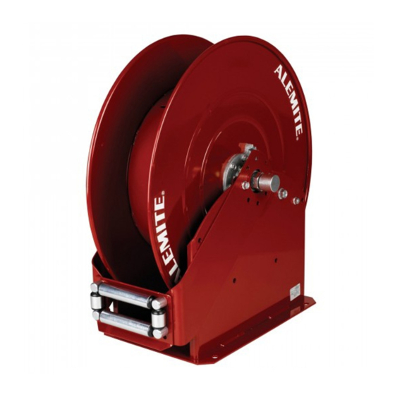
Description Fig. 1 High-capacity reel model 7340 and 7341 Mounting High-capacity reel models 7340 and 7341 are designed for severe environments, such as a lubrication truck. They can also mount to a ceiling or wall. NOTE The hose guide arms can attach to the base assembly in five (5) different positions. -
Page 4: Overhaul
Arms and power spring assembly Disassembly NOTE 9 Remove nuts (13) that secure long Prior to performing any maintenance arm (34) to bolts (31). procedure, the following safety precau- NOTE 9.1 Remove the arm from the bolts. tions must be observed. Personal injury Prior to disassembly, release tension on 10 Remove nuts (1) and screws (5) that may occur. -
Page 5: Clean And Inspect
Sheave assembly Clean and inspect Assembly 19 Remove the sheave assembly (with attached components) from the base NOTE NOTE assembly. Use the appropriate repair kit for Prior to assembly, certain components 20 Remove the shaft (with attached compo- replacement parts. Make sure all the require lubrication. -
Page 6: Power Spring Assembly And Arms
Ribbed-neck bolts 13 Install the first bearing and housing 23 Install the power spring assembly onto assembly (extended side first) onto the arbor. shaft (8) and onto the bolts. 23.1 Make sure the end of the power NOTE 14 Attach the bearing and housing spring properly engages the arbor. -
Page 7: Swivel Assembly
37 Screw swivel assembly (36 or 39) into the shaft. 37.1 Tighten the swivel assembly securely. 38 Check to ensure the swivel assembly moves freely. Fig. 2 High-capacity reel - section view - model 7340 shown Power spring gasket Flat washers Wave washer Retaining ring... -
Page 8: Installation
Delivery hose attachment Installation 1 Mount the reel assembly with the proper hardware. WARNING CAUTION WARNING Do not exceed the lowest pressure rat- Never connect rigid piping to the Swivel Precautions must be taken to ensure ing of any component in the system. assembly. -
Page 9: Accessories Attachment And Pressurization
Fig. 3 Space required for banked reels (with bolt pattern dimensions) Ø 25 in (635 mm) 26.16 in (665 mm) 2.5 in (63.5 mm) 14.96 in 11.44 in (380 m) (290 mm) 13.38 in (340 mm) Ø 0.53 in To supply line (13.5 mm) Clamp (not included) Connecting hose (not included) -
Page 10: Adjusting Spring Tension
Reel operation Fig. 4 Clamp attached to sheave assembly WARNING Do not exceed lowest pressure rating of any component in system. Never point a control valve at any portion of body or another person. Lubricant discharged at high velocity can penetrate skin and cause severe injury. -
Page 11: Reel Packages
Reel packages 1 Instruct the assistant to grip the hose securely with both hands to prevent uncontrolled retraction. Hose reel models 7340 and 7341 are 2 Grip the sheave assembly securely with included in the reel packages listed below. gloved hands. -
Page 12: Troubleshooting Chart
Troubleshooting chart Indications Possible problems Solution Reel does not latch. Extension spring (24) broken or not attached to pawl and Replace or secure extension spring (24). shaft assembly (25). Reel does not retract. 1. Power spring broken. 1. Replace power spring assembly (12). 2. -
Page 13: Exploded View
Fig. IPB 1 High-capacity reel model 7340 and 7341 - exploded view Note: Torque screw (32) to 42 to 48 ft.lbf (57 - 65 Nm). Repair kit 393724 pawl and shaft assembly kit. Repair kit 393723 hose guide Repair kit 393695 high pressure swivel repair kt. -
Page 14: Parts List
Sheave assembly Shaft and flange assembly 339464 Key, square 339521 Screw, in -18 x (19 mm) in Union, 90 °, in NPTF x in NPSM 7340 339459-1 Union, 90 °, in NPTF x in NPSM 7341 339459-2 Bushing 7340 131586 Shaft... - Page 15 This page left intentionally blank.
- Page 16 ® Alemite, LLC is a registered trademark. The contents of this publication are the copyright of the publisher and may not be reproduced (even extracts) unless prior written permission is granted. Every care has been taken to ensure the accuracy of the information contained in this publication but no liability can be accepted for any loss or damage whether direct, indirect or consequential arising out of the use of the information contained herein.
Need help?
Do you have a question about the 7340 and is the answer not in the manual?
Questions and answers