Table of Contents
Advertisement
Quick Links
Description
Mounting
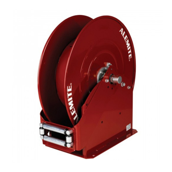
High-capacity reel models 7340 and 7341 are
designed for severe environments, such as a lubrication
truck. They can also mount to a ceiling* or wall.
NOTE: The Hose Guide Arms can attach
to the Base Assembly in five (5) different
positions.
These reels mount as a single unit or in banks of as
many as required. See Figure 4 for details.
Operation
Each model reel is spring-powered and self-
retracting. When the hose is extended, the reel can be
latched on either of two ratchet sections per revolution
of the sheave. A pull releases the latch from the ratchet
and allows the hose to retract onto the reel.
Reel Models 7340 and 7341
Reel model 7340 contains a high-pressure swivel
assembly. The reel is designed to dispense grease
through a 3/8 " ID two-wire braid delivery hose.
A medium-pressure swivel assembly is included
with model 7341. This reel is designed for 1/2 " ID
hose to dispense fluid lubricants (such as motor and
gear oil and automatic transmission fluid) and air.
Delivery Hose
Each model reel manages a maximum length of
delivery hose as indicated in Table 1.
Reel
Delivery Hose
Model
Description
7340
3/8 " ID Two-Wire Braid
1/2 " ID Single-Wire Braid
7341
1/2 " ID Air
Table 1 Reel Model Comparison to Delivery Hose
This document contains confidential information that is the property of Alemite Corporation
670783
and is not to be copied, used, or disclosed to others without express written permission.
Service Guide
High-Capacity Reel
Maximum Length
of Hose in Feet
80
100
Alemite Corporation
PO Box 473515, Charlotte, North Carolina 28247-3515
www.alemite.com
©
Copyright
2003 by Alemite Corporation
Inlet
Reel Model
(Swivel)
7340
3/8 " NPTF (f)
7341
1/2 " NPTF (f)
Figure 1 High-Capacity Reel Model 7340 and 7341
CAUTION
* The base of the reel must be at a height no greater
than 16 feet (4.9 m) from the floor to comply with the
warranty.
7340
7341
Reel Max. Pressure
Outlet
psi
3/8 " NPSM (f)
6000
1/2 " NPSM (f)
1500
SER 7340
Revision (2-03)
Bars
414
103
Advertisement
Table of Contents

Related Manuals for Alemite 7340


Summary of Contents for Alemite 7340
- Page 1 PO Box 473515, Charlotte, North Carolina 28247-3515 www.alemite.com © Copyright 2003 by Alemite Corporation SER 7340 This document contains confidential information that is the property of Alemite Corporation 670783 Revision (2-03) and is not to be copied, used, or disclosed to others without express written permission.
- Page 2 SER 7340 High-Capacity Reel Figure 2 High-Capacity Reel Model 7340 and 7341 - Exploded View Revision (2-03) Alemite Corporation...
- Page 3 Key, Square 50876 Screw, 5/16 " -18 x 3/4 " 131586 339459-1 Union, 90 °, 3/8 " NPTF x 3/8 " NPSM 7340 X171000-5 (22) 339459-2 Union, 90 °, 1/2 " NPTF x 1/2 " NPSM 7341 171007-33 (16) 131586...
- Page 4 SER 7340 High-Capacity Reel Hose Guide Assembly IMPORTANT: Prior to performing any main- tenance procedure, the following safety pre- 6. Remove Nuts (13) that secure Post and Shaft cautions must be observed. Personal injury Assemblies (18) and (19) to Hose Guide Plate (17).
-
Page 5: Base Assembly
High-Capacity Reel SER 7340 17. Remove Retaining Ring (16) that secures Shaft (8) to Clean and Inspect Bearing (28). NOTE: Use the appropriate repair kit for • Do not remove the Shaft at this time. replacement parts. Make sure all the compo- 18. - Page 6 SER 7340 High-Capacity Reel Ribbed-Neck Bolts 17. Tighten the Nuts on the opposite Bearing alternately and evenly. IMPORTANT: Make sure the longer Bolts (31) mount on the Pawl Assembly side of the 18. Install Retaining Ring (16) onto the Shaft.
- Page 7 34. Secure the hose guide assembly to the Arms with Nuts • Tighten the Swivel Assembly securely. (13). 38. Check to ensure the Swivel Assembly moves freely. Figure 3 High-Capacity Reel - Section View - Model 7340 Shown Alemite Corporation Revision (2-03)
-
Page 8: Bench Test
SER 7340 High-Capacity Reel 1. Mount the reel assembly with the proper hardware. Bench Test While facing the Ratchet, turn the reel in a clockwise CAUTION direction and allow the Ratchet to latch the Pawl. Never connect rigid piping to the Swivel assembly. - Page 9 High-Capacity Reel SER 7340 Figure 4 Space Required for Banked Reels (with Bolt Pattern Dimensions) Delivery Hose Attachment 8. Connect the delivery hose to the 90 ° Union. • Make sure the connection is secure. HINT: Orient the hose to allow its natural WARNING curve to match the Sheave.
- Page 10 SER 7340 High-Capacity Reel Should the power spring tension require Accessories Attachment and Pressurization adjustment: 11. Install the control valve onto the delivery hose. Adjusting Spring Tension 12. Pressurize the system. • Check for leaks. CAUTION 13. Install and secure the hose stop to the delivery hose at the desired position.
- Page 11 High-Capacity Reel SER 7340 Latch Lockout Reel Operation Over-Rotation of the Reel WARNING IMPORTANT: Do not extend the hose from the reel too rapidly. Too much velocity (when Do not exceed the lowest pressure rating the hose is fully extended) can cause the reel of any component in the system.
-
Page 12: Troubleshooting Chart
High-Capacity Reel Reel Packages Hose reel models 7340 and 7341 are included in the reel packages listed below. IMPORTANT: The Power Spring tension is preset at the factory for most installations. Once the reel pack- age is installed and the system is pressurized, refer to the section entitled Checking Spring Tension.
Need help?
Do you have a question about the 7340 and is the answer not in the manual?
Questions and answers