
Subscribe to Our Youtube Channel
Related Manuals for IFM AL1340


Summary of Contents for IFM AL1340
- Page 1 > > Operating Instructions IO-Link Master with Modbus TCP Interface DataLine 4 Ports IP 65 / IP 66 / IP 67 AL1340 HW Revision: AB Firmware: 2.3.x LR DEVICE: 1.5.0.x English...
- Page 2 IO-Link Master with Modbus TCP Interface DataLine 4 Ports IP 65 / IP 66 / IP 67 Contents Preliminary note Legal and copyright information ................... 5 Purpose of the document ..................... 5 Explanation of Symbols ....................... 6 Modification history ......................6 Safety instructions General ..........................
- Page 3 9.2.15 MQTT support ..........................57 9.2.16 Programmers' notes ........................58 Modbus TCP ........................63 9.3.1 Integrate the AL1340 into the Modbus project ................63 9.3.2 Set IO-Link master ........................65 9.3.3 Set IO-Link ports ........................66 9.3.4 Read input data of several IO-Link ports ..................67 9.3.5...
-
Page 4: Acyclic Commands
Electrical connection ........................85 13.2 Modbus TCP ........................86 13.2.1 Register ............................87 13.2.2 Acyclic commands ........................103 13.3 ifm IoT Core ........................112 13.3.1 Overview: IoT profile ........................ 113 13.3.2 Overview: IoT types ........................118 13.3.3 Overview: IoT services ......................119 Index... - Page 5 Legal and copyright information 33117 © All rights reserved by ifm electronic gmbh. No part of this manual may be reproduced and used without the consent of ifm electronic gmbh. All product names, pictures, companies or other brands used on our pages are the property of the respective rights owners: ...
- Page 6 IO-Link Master with Modbus TCP Interface DataLine 4 Ports IP 65 / IP 66 / IP 67 > Explanation of Symbols 34171 WARNING! Death or serious irreversible injuries may result. CAUTION! Slight reversible injuries may result. NOTICE! Property damage is to be expected or may result. Important note Non-compliance can result in malfunction or interference Information...
- Page 7 IO-Link Master with Modbus TCP Interface DataLine 4 Ports IP 65 / IP 66 / IP 67 Safety instructions Content General ..............................7 Required background knowledge ......................7 Safety symbols on the device ........................7 IT safety ..............................8 Tampering with the unit ..........................8 28333 >...
- Page 8 IO-Link Master with Modbus TCP Interface DataLine 4 Ports IP 65 / IP 66 / IP 67 IT safety 54678 NOTICE! If the device is operated in an unprotected network environment. > Unauthorised read or write access to data is possible. >...
- Page 9 IO-Link Master with Modbus TCP Interface DataLine 4 Ports IP 65 / IP 66 / IP 67 Intended use Content Permitted use ............................9 Prohibited use ............................9 34079 > Permitted use 34209 The IO-Link master serves as a gateway between intelligent IO-Link devices and the Modbus TCP network.
- Page 10 IO-Link Master with Modbus TCP Interface DataLine 4 Ports IP 65 / IP 66 / IP 67 Function Content Communication, parameter setting, evaluation ..................11 Digital inputs ............................12 IO-Link supply ............................12 33836...
- Page 11 IO-Link master (IO-Link revision 1.0 and 1.1) 4 IO-Link ports for connection of IO-Link devices Provision of process data of the connected IO-Link devices for LR SMARTOBSERVER monitoring software (→ www.ifm.com) > 4.1.2 Modbus TCP 33676 The device offers the following Modbus TCP functions: ...
- Page 12 34210 The device provides the following configuration options: Parameter setting of the IO-Link master of the AL1340 with LR DEVICE parameter setting software, Modbus TCP projection software or ifm IoT-Core services. Parameter setting of the connected IO-Link devices (sensors, actuators) with LR DEVICE parameter setting software, Modbus TCP projection software or ifm IoT-Core services ...
- Page 13 IO-Link Master with Modbus TCP Interface DataLine 4 Ports IP 65 / IP 66 / IP 67 Mounting Content Mount the device ............................13 34058 > Mount the device 34059 ► Disconnect the system from power before installation. ► For installation choose a flat mounting surface. ►...
- Page 14 IO-Link Master with Modbus TCP Interface DataLine 4 Ports IP 65 / IP 66 / IP 67 Electrical connection Content Notes ..............................14 Modbus TCP ports ..........................15 IoT port ..............................15 IO-Link ports ............................16 Connect the device ..........................18 33805 > Notes 51957 A qualified electrician must connect the unit.
- Page 15 IO-Link Master with Modbus TCP Interface DataLine 4 Ports IP 65 / IP 66 / IP 67 Modbus TCP ports 33671 ► Connect the device via the M12 socket X21 and/or X22 to the Modbus TCP network (e.g. Modbus TCP PLC, additional Modbus TCP device) ...
- Page 16 > IO-Link ports 51958 The IO-Link ports of the AL1340 meet the requirements of the IO-Link specifications 1.0 to 1.1.2. ► Please note the information concerning IO-Link wiring! ► Cover unused sockets with M12 protective caps (art. no.: E73004). ...
- Page 17 IO-Link Master with Modbus TCP Interface DataLine 4 Ports IP 65 / IP 66 / IP 67 > 6.4.2 Connect IO-Link devices for Class B operation 51960 Notes on wiring: For Class B operation, the IO-Link device must be supplied with an additional auxiliary voltage UA using a Y connection cable.
- Page 18 IO-Link Master with Modbus TCP Interface DataLine 4 Ports IP 65 / IP 66 / IP 67 Connect the device 33882 ► Disconnect power. ► Connect the IO-Link Master via M12 socket X31 to 24 V DC (20...28 V SELV/PELV; according to EN61010-1, secondary circuit with maximum 30 V DC supplied by mains circuit up to 300 V of overvoltage category II).
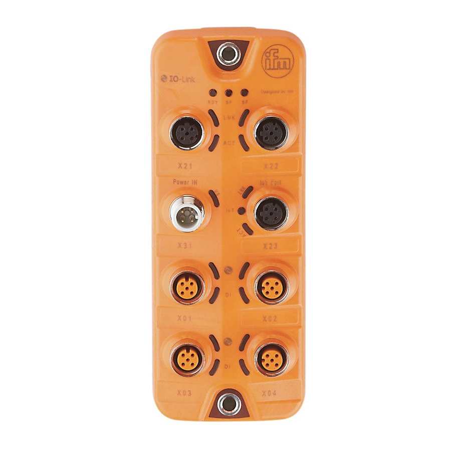
- Page 19 IO-Link Master with Modbus TCP Interface DataLine 4 Ports IP 65 / IP 66 / IP 67 Operating and display elements Content Overview ..............................19 LED indicators ............................20 34063 > Overview 34356 RDY, RUN and ERR status LEDs → Status LEDs (→...
- Page 20 IO-Link Master with Modbus TCP Interface DataLine 4 Ports IP 65 / IP 66 / IP 67 > LED indicators 34047 The device only has the following LED indicators: > 7.2.1 Status LEDs 34436 The RDY LED indicates the status of the gateway. The RUN LED indicates the current state of the Modbus TCP state machine.
- Page 21 IO-Link Master with Modbus TCP Interface DataLine 4 Ports IP 65 / IP 66 / IP 67 7.2.3 IoT port 34043 The IoT port (X23) has the 3 LNK, ACT and IoT LEDs. The LEDs indicate the status of the Ethernet connection and the device identification.
- Page 22 (→ Operating and display elements (→ S. 19)). To enable parameter setting of the AL1340, the IoT interface and / or the fieldbus interface must be configured according to the network environment. ► Configure IoT interface (LR DEVICE: →...
- Page 23 ► Connect laptop/PC and AL1340 via the Ethernet internet. ► Start web browser. ► Enter the IP address of the AL1340 into the address field of the browser and press [ENTER] to confirm. > Web browser shows the web interface of the device.
- Page 24 IO-Link Master with Modbus TCP Interface DataLine 4 Ports IP 65 / IP 66 / IP 67 Configuration Content LR DEVICE .............................25 ifm IoT Core ............................38 Modbus TCP ............................63 33858...
- Page 25 Firmware: Reset device to factory settings ....................36 Firmware: Reboot the device........................36 Configure IO-Link devices ........................37 33692 On delivery, the AL1340 is configured with the factory settings (→ Factory settings (→ S. 79)). Required software: LR DEVICE (1.5.0.x or higher) (art.-no.: QA0011/QA0012)
- Page 26 IO-Link master and the connected IO-Link devices without being connected to the AL1340 (OFFLINE mode). The configuration created in this way can be stored as a file (*.lrp) and loaded to the AL1340 and activated at a later date.
- Page 27 IO-Link Master with Modbus TCP Interface DataLine 4 Ports IP 65 / IP 66 / IP 67 > 9.1.2 IoT: Configure IP settings 34049 For access to the IO-Link master via the IT infrastructure the user has to set the IP settings of the IoT port.
- Page 28 IO-Link Master with Modbus TCP Interface DataLine 4 Ports IP 65 / IP 66 / IP 67 > 9.1.3 IoT: Configure security mode 54680 The IoT interface of the IO-Link offers a security mode. It enables secure data transmission via transport encryption and restriction of the access to IO-Link masters and IO-Link devices via user authentication.
- Page 29 IO-Link Master with Modbus TCP Interface DataLine 4 Ports IP 65 / IP 66 / IP 67 > 9.1.4 IoT: Configure access rights 34046 The access rights define which instance may read and / or write the parameter data, process data and event/diagnostic messages.
- Page 30 2147483647 2147483647 ms [Application Tag] Source identifier of the IO-Link master in the Factory setting: AL1340 structure of LR AGENT or LR SMARTOBSERVER (String32) After changing the parameter [Port LR Agent or SMARTOBSERVER] or [Application Tag], it may take 120 seconds before the device establishes a new TCP connection.
- Page 31 IO-Link Master with Modbus TCP Interface DataLine 4 Ports IP 65 / IP 66 / IP 67 > 9.1.6 Fieldbus: Configure IP settings 54698 The configuration of the IP settings of the fieldbus port is only possible via LR DEVICE and IoT.
- Page 32 IO-Link Master with Modbus TCP Interface DataLine 4 Ports IP 65 / IP 66 / IP 67 > 9.1.7 Fieldbus: set the length of the process data 54681 To set the length of the process data to be transmitted and the arrangement of the bytes: ►...
- Page 33 IO-Link Master with Modbus TCP Interface DataLine 4 Ports IP 65 / IP 66 / IP 67 9.1.9 IO-Link ports: Configure operating mode 33694 The IO-Link ports X01...X04 of the device support the following operating modes: Digital input (DI): binary input signal at pin 4 (C/Q) of the IO-Link port ...
- Page 34 Restore] [Vendor ID] ID of the manufacturer that is to be validated 0...65535 Factory setting: 0# ifm electronic: 310 [Device ID] ID of the IO-Link device that is to be validated 0...16777215 Factory setting: 0 ► Save changed values on the device.
- Page 35 ► Save changed values on the device. > 9.1.12 Info: Show device information 34065 To read the general information of the ifm IO-Link master: ► Select [Info] menu. > The menu page shows the current settings. Name Description...
- Page 36 When rebooting the device, all settings are kept. To restart the AL1340: ► Select [Firmware] menu. > The menu page shows the current settings. ► Click on [Reboot] to reboot the device. > LR DEVICE reboots the ifm IO-Link master.
- Page 37 ► Under [ONLINE]: Click on the required IO-Link master. > LR DEVICE automatically detects the IO-Link devices connected to the IO-Link master (e.g. ifm sensor KG5065). Configure IO-Link device ► Mouse click on the port to which the IO-Link device is connected.
- Page 38 9.2.1 First steps 52245 To read the device description of the AL1340: ► Send the following POST request to the AL1340: {"code":"request","cid":-1,"adr":"gettree"} > AL1340 returns the device description as structured JSON object. ► Identify all substructures and the data points contained therein in the tree structure of the JSON object.
- Page 39 IO-Link Master with Modbus TCP Interface DataLine 4 Ports IP 65 / IP 66 / IP 67 > 9.2.2 General functions 52246 The AL1340 is of type device (→ Overview: IoT types (→ S. 118)). Besides gettree, the following services can be applied to the root element of type device. Service Description ../getidentity...
- Page 40 IO-Link Master with Modbus TCP Interface DataLine 4 Ports IP 65 / IP 66 / IP 67 > 9.2.3 Configure IoT interface 33888 Via the IoT interface the AL1340 wil be integrated in the IT network. Substructure: iotsetup Avalable data points: Name Description Access ../accessrights...
- Page 41 IO-Link Master with Modbus TCP Interface DataLine 4 Ports IP 65 / IP 66 / IP 67 > 9.2.4 IoT interface: Configure security mode 54683 The access to the IoT interface of the IO-Link master can be protected with a security mode: Sub-structure: iotsetup Available data points: Name...
- Page 42 IO-Link Master with Modbus TCP Interface DataLine 4 Ports IP 65 / IP 66 / IP 67 > Example: Activate security mode 54701 Task: Activate the security mode of the IO-Link interface of the IO-Link master. Set the password "password" (Base64 coded: cGFzc3dvcmQ=) Solution: The activation sonsists of 2 steps: Activate security mode Use service setdata with datapoint iotsetup/security/securitymode to activate the security mode.
- Page 43 IO-Link Master with Modbus TCP Interface DataLine 4 Ports IP 65 / IP 66 / IP 67 > Example: Request with authentication 54685 Task: The temperature of the IO-Link master is to be read. The security function is enabled (current password: password).
- Page 44 IO-Link Master with Modbus TCP Interface DataLine 4 Ports IP 65 / IP 66 / IP 67 > 9.2.5 Configure the fieldbus interface 34476 Via the fieldbus interface (ports X21 / X22) the AL1340 will be integrated in the Modbus TCP network. Substructure: fieldbussetup Available data points: Last name Description Access ../fieldbusfirmware...
- Page 45 IO-Link Master with Modbus TCP Interface DataLine 4 Ports IP 65 / IP 66 / IP 67 > 9.2.6 Configure IO-Link ports 52248 The user can configure the IO-Link ports X01...X04 separately. Substructure: iolinkmaster/port[n] (n = 1...4). Available data points: Name Description Access...
- Page 46 IO-Link Master with Modbus TCP Interface DataLine 4 Ports IP 65 / IP 66 / IP 67 > Example: Clone the Data Storage of an IO-Link port 52344 Task: Save the Data Storage of IO-Link port X02 of IO-Link master 1 and restore the data at IO-Link master 2.
- Page 47 9.2.7 Configure IO-Link devices 52249 The ifm IoT Core supports the configuration of the connected IO-Link devices. A parameter is accessed via IO-Link index and subindex (→ IO Device Description (IODD) of the device). Substructure: iolinkmaster/port[n]/iolinkdevice (n = 1...4) Applicable services:...
- Page 48 Example: Change the parameter value of an IO-Link device 33844 Task: Set the output configuration OUT1 of the ifm temperature sensor TN2531 at IO-Link port X02 to the value "Hnc / hysteresis function, normally closed". Solution: Change the parameter [ou1] of the sensor to the value 4 using the iolwriteacyclicdata service.
- Page 49 > Example: Change name of the IO-Link master a33823 Task: Set the name of the IO-Link master to AL1340 for the representation in the LR SMARTOBSERVER. Solution: Change the parameter [Application Tag] with the setdata service to the value [AL1340].
- Page 50 Example: Read process data of an IO-Link device 33842 Task: Read the current measured value of the ifm temperature sensor TN2531 at IO-Link port X02 Solution: Read the data point for the process input data with the getdata service. ...
- Page 51 IO-Link Master with Modbus TCP Interface DataLine 4 Ports IP 65 / IP 66 / IP 67 > 9.2.10 Control IO-Link master 52251 Different services and management functions can be carried out on the IO-Link master. Substructure: firmware Available data points: Name Description Access...
- Page 52 IO-Link Master with Modbus TCP Interface DataLine 4 Ports IP 65 / IP 66 / IP 67 > Example: Update firmware 52252 Task: Update the firmware of the device; size of the firmware file: 356676 bytes Solution: The firmware is transferred to the device in fragments (chunks). The size of the fragments depends on the size of the flash memory of the IO-Link master.
- Page 53 IO-Link Master with Modbus TCP Interface DataLine 4 Ports IP 65 / IP 66 / IP 67 > 9.2.11 Read diagnostic data of the AL1340 52253 The user can read diagnostic data of the status of the IO-Link masters. Substructure: processdatamaster...
- Page 54 ../bootloaderrevision Bootloader version ../extensionrevisions Firmware and bootloader version ../fieldbustype Fieldbus r ... read only Additional information about the AL1340 can be read with the getidentity service (→ Service: getidentity (→ S. 122)). > 9.2.13 Read information about IO-Link devices 52339 The user can obtain information about the IO-Link devices connected to the IO-Link ports.
- Page 55 IO-Link Master with Modbus TCP Interface DataLine 4 Ports IP 65 / IP 66 / IP 67 > 9.2.14 Subscribe to events 52255 If a data point has the subelement datachanged, the user can subscribe to events. Available data points: Name Description Access...
- Page 56 IO-Link Master with Modbus TCP Interface DataLine 4 Ports IP 65 / IP 66 / IP 67 > Example: Subscribe to event 33853 Task: The current values of the following parameters should be sent regularly to a network server with IP address 192.168.0.4: product name of the IO-Link device at IO-Link port X02, cyclic input data of the IO-Link device at IO-Link port X02 and the operating temperature of the IO-Link master.
- Page 57 9.2.15 MQTT support 54699 The AL1340 can operate as a client in a MQTT-based communication environment. By using the subscribe service it is possible to send messages to a MQTT broker (PUBLISH). > Example: Publish the temperature to an MQTT broker...
- Page 58 IoT Core: General information 52256 The DataLine device family has an IoT Core. The IoT Core allows the user to address the AL1340 from IT networks via a REST API and to integrate it into Internet-of-Things applications. A device description is stored on the AL1340. This device description is a structured, machine-readable data object in JSON format.
- Page 59 Correlation ID for the assignment of request and return resp_data Value of the data point; depending on the data type of the data point diag_code Diagnostic code (→ IoT Core: Diagnostic codes (→ S. 62)) > Example: GET request 54033 Request (via browser): http://192.168.0.250/devicetag/applicationtag/getdata Response: "cid":-1, "data":{"value":"AL1340"}, "code":200...
- Page 60 IO-Link Master with Modbus TCP Interface DataLine 4 Ports IP 65 / IP 66 / IP 67 > POST request 54700 Using a POST request the user has read and write access to a data point. The syntax of the request to the IoT Core is: "code":"code_id", "cid":id, "adr":"data_point/service",...
- Page 61 IO-Link Master with Modbus TCP Interface DataLine 4 Ports IP 65 / IP 66 / IP 67 > Example: POST request 54035 Request: "code":"request", "cid":4711, "adr":"devicetag/applicationtag/getdata" Response: "cid":4711, "data":{"value":"AL1340"}, "code":200...
- Page 62 IO-Link Master with Modbus TCP Interface DataLine 4 Ports IP 65 / IP 66 / IP 67 > IoT Core: Diagnostic codes 54688 Code Text Description Request successfully processed OK but needs reboot Request successfully processed; IO-Link master must be restarted OK but block request not finished Request successfully processed;...
- Page 63 Integrate the AL1340 into the Modbus project 34456 The AL1340 provides the functionality of a Modbus-TCP slave. The user can integrate the IO-Link master via the profile of a generic Modbus-TCP slave to a fieldbus project. The IO-Link master, the IO-Link Ports and the process data are configured via the Modbus register of...
- Page 64 3. [Name]: Enter a unique name ► Click on [Add Device]. > Device tree shows AL1340 as sub-node of the Modbus-TCP master. Configure Modbus-TCP slave ► In the following tabs, set the parameters as required: 1. [General]: Set IP address and Unit ID 2.
- Page 65 IO-Link Master with Modbus TCP Interface DataLine 4 Ports IP 65 / IP 66 / IP 67 > 9.3.2 Set IO-Link master 54624 →Configuration Area Register area for the access to the configuration of the IO-Link master: (→ S. 88) The area contains the following data: ...
- Page 66 Port X03: Port Configuration 9018 Port X04: Port Configuration r/w = read and write In addition, the user can set the IO-Link ports of the AL1340 via the following acyclic commands: →Command 0x10 – Set mode "Set Mode": (→ S. 104) ...
- Page 67 IO-Link Master with Modbus TCP Interface DataLine 4 Ports IP 65 / IP 66 / IP 67 > 9.3.4 Read input data of several IO-Link ports 34465 Register area for compact access to the input data of the IO-Link ports X01…X04: →Input Data (→...
- Page 68 IO-Link Master with Modbus TCP Interface DataLine 4 Ports IP 65 / IP 66 / IP 67 > 9.3.5 Read input data of individual IO-Link ports 34466 →Single Port Access Register area for separate access to input data of the individual IO-Link ports: (→...
- Page 69 IO-Link Master with Modbus TCP Interface DataLine 4 Ports IP 65 / IP 66 / IP 67 > 9.3.6 Write output data of several IO-Link ports 34472 Register area for compact access to the output data of the IO-Link ports X01…X04: →Output Data (→...
- Page 70 IO-Link Master with Modbus TCP Interface DataLine 4 Ports IP 65 / IP 66 / IP 67 > 9.3.7 Write output data of individual IO-Link ports 34452 →Single Port Access Register area for separate access to output data of individual IO-Link ports: (→...
- Page 71 IO-Link Master with Modbus TCP Interface DataLine 4 Ports IP 65 / IP 66 / IP 67 > 9.3.8 Read diagnostic information and events 34439 Register area for the access to diagnostic information of the IO-Link ports X01…X04:→Diagnostic data (→ S. 90) The area contains the following data: ...
- Page 72 9.3.9 Read device information 34451 The user can read device information using the FC43. The AL1340 supports the following data records ("Read Device ID code"): Basic Device Identification (0x01): contained data objects: → Modbus TCP specification Regular Device Identification (0x02): contained data objects: → Modbus TCP specification ...
- Page 73 ► After every read or write access check the validity of the transmitted data (→ Mapping: PQI (→ S. 99)). > Supported function codes 34440 The AL1340 supports the following function codes for read and/or write access to the Modbus register: Function code Function name / description 03 (0x03) Read Multiple Registers 04 (0x04)
- Page 74 Response Function Code: Request Function Code Response Data: Requested data If an error occurs while accessing the registers, the AL1340 replies with an error code instead of the function code. The response message has the following content: Response Function Code: Error Code (= Request Function Code + 0x80) ...
- Page 75 IO-Link Master with Modbus TCP Interface DataLine 4 Ports IP 65 / IP 66 / IP 67 > Use acyclic services 34471 The AL1340 has a command interface to execute acyclic commands. A cyclic command consists of a request and a response. Register Contents Access Command Request Channel (Fieldbus PLC >>>...
- Page 76 IO-Link Master with Modbus TCP Interface DataLine 4 Ports IP 65 / IP 66 / IP 67 Maintenance, repair and disposal Content Cleaning process ............................76 Update firmware .............................77 Replace IO-Link device ..........................78 51990 The operation of the unit is maintenance-free. ►...
- Page 77 ► Enter the following into the address field of the browser and confirm with [ENTER]: http://<IP address of the device>/web/update > Web browser shows the [Firmware Update] page. Load new firmware to AL1340 ► Click on [Select file]. > Dialogue window appears.
- Page 78 ► Save changes. Replace IO-Link device ► Disconnect old IO-Link device from IO-Link master. ► Connect new IO-Link device with the same IO-Link port of the AL1340. > IO-Link master copies parameter values from the data memory to the new IO-Link device.
- Page 79 IO-Link Master with Modbus TCP Interface DataLine 4 Ports IP 65 / IP 66 / IP 67 Factory settings 34509 In the factory settings, the device has the following parameter settings: Parameter Factory setting [IP address] (Modbus TCP) 192.168.1.250 [Subnet mask] (Modbus TCP) 255.255.255.0 [IP gateway address] (Modbus TCP) 0.0.0.0...
- Page 80 IO-Link Master with Modbus TCP Interface DataLine 4 Ports IP 65 / IP 66 / IP 67 Accessories 33870 List of accessories of AL1340: → www.ifm.com > Product page > Accessories...
- Page 81 IO-Link Master with Modbus TCP Interface DataLine 4 Ports IP 65 / IP 66 / IP 67 Appendix Content Technical data ............................82 Modbus TCP ............................86 ifm IoT Core ............................112 33879...
- Page 82 IO-Link Master with Modbus TCP Interface DataLine 4 Ports IP 65 / IP 66 / IP 67 > 13.1 Technical data Content Application ..............................82 Electrical data ............................82 Inputs / outputs ............................82 Inputs ..............................83 Outputs ..............................83 Interfaces ..............................83 Operating conditions ..........................84 Approvals / tests .............................84 Mechanical data ............................84 Electrical connection ..........................85...
- Page 83 IO-Link Master with Modbus TCP Interface DataLine 4 Ports IP 65 / IP 66 / IP 67 > 13.1.4 Inputs 34069 Inputs Number of digital inputs 8; (IO-Link Port Class A: 4 x 2) Switching level high [V] 11...28 Switching level low [V] 0...5 Digital inputs protected against short circuits >...
- Page 84 IO-Link Master with Modbus TCP Interface DataLine 4 Ports IP 65 / IP 66 / IP 67 13.1.7 Operating conditions 34062 Operating conditions Applications Indoor use Ambient temperature [°C] -25...60 Storage temperature [°C] -25...85 Max. perm. relative air humidity [%] Max.
- Page 85 IO-Link Master with Modbus TCP Interface DataLine 4 Ports IP 65 / IP 66 / IP 67 > 13.1.10 Electrical connection 33806 Voltage supply IN X31 Plug and socket connection Wiring + 24 V DC (US) GND (US) Ethernet IN / OUT X21, X22 Plug and socket connection Wiring TX +...
- Page 86 IO-Link Master with Modbus TCP Interface DataLine 4 Ports IP 65 / IP 66 / IP 67 > 13.2 Modbus TCP Content Register ..............................87 Acyclic commands ..........................103 33674...
- Page 87 IO-Link Master with Modbus TCP Interface DataLine 4 Ports IP 65 / IP 66 / IP 67 > 13.2.1 Register Content Configuration Area ..........................88 Diagnostic data ............................90 Input Data ...............................93 Output Data ............................96 Single Port Access ..........................98 Acyclic Command Channel ........................100 34442 The AL1340 saves the configuration data, process data and status/diagnostic data in Modbus registers.
- Page 88 IO-Link Master with Modbus TCP Interface DataLine 4 Ports IP 65 / IP 66 / IP 67 > Configuration Area 34470 Register Contents Bits 8-15 Bits 0-7 8998 Access Rights Process Data Length 8999 reserved Byte Swap 9000 Port X01: Port Configuration (→ Mapping: port configuration (→...
- Page 89 IO-Link Master with Modbus TCP Interface DataLine 4 Ports IP 65 / IP 66 / IP 67 > Mapping: port configuration 34478 Bits 8-15 Bits 0-7 Port Mode Master Cycle Time reserved Validation ID Vendor ID reserved Device ID (MSB) Device ID Device ID (LSB) Failsafe Mode -- IO-Link...
- Page 90 IO-Link Master with Modbus TCP Interface DataLine 4 Ports IP 65 / IP 66 / IP 67 Diagnostic data SYS_OBJECTID> Register Contents Bits 8-15 Bits 0-7 Port X01: → reserved Mapping: Diagnostics (→ S. 91) Port X01: Vendor ID reserved Port X01: Device ID (MSB) Port X01: Device ID Port X01: Device ID (LSB)
- Page 91 IO-Link Master with Modbus TCP Interface DataLine 4 Ports IP 65 / IP 66 / IP 67 > Mapping: Diagnostics 34504 Bit 7 Bit 6 Bit 5 Bit 4 Bit 3 Bit 2 Bit 1 Bit 0 reserved Wrong Length Wrong Length Cycle time Wrong...
- Page 92 IO-Link Master with Modbus TCP Interface DataLine 4 Ports IP 65 / IP 66 / IP 67 > Mapping: events 34481 reserved Event 1: Event 1: Event 1: Event 1: Mode Type Instance Event 1: Code reserved Event 2: Event 2: Event 2: Event 2: Mode...
- Page 93 IO-Link Master with Modbus TCP Interface DataLine 4 Ports IP 65 / IP 66 / IP 67 > Input Data 34447 Register Contents Port X01...X04: Digital Input - Pin 2 / Pin 4 (DI) (→ Mapping: digital input data (→ S. 94)) Port X01...X04: Diagnostic Information (→...
- Page 94 IO-Link Master with Modbus TCP Interface DataLine 4 Ports IP 65 / IP 66 / IP 67 > Mapping: digital input data 34484 res. res. res. res. X04: X03: X02: X01: res. res. res. res. X04: X03: X02: X01: pin 2 pin 2 pin 2 pin 2...
- Page 95 IO-Link Master with Modbus TCP Interface DataLine 4 Ports IP 65 / IP 66 / IP 67 > Mapping: Status information IO-Link ports 34485 res. res. res. res. X04: X03: X02: X01: res. res. res. res. X04: X03: X02: X01: Data Data Data...
- Page 96 IO-Link Master with Modbus TCP Interface DataLine 4 Ports IP 65 / IP 66 / IP 67 > Output Data 34488 Register Contents Bits 8-15 Bits 0-7 Port X01...X04: Digital Output - Pin 4 (DO) (→ Mapping: Digital output data (→...
- Page 97 IO-Link Master with Modbus TCP Interface DataLine 4 Ports IP 65 / IP 66 / IP 67 > Mapping: Digital output data 34493 res. res. res. res. res. res. res. res. res. res. res. res. X04: 0X03: X02: X01: Pin 4 Pin 4 Pin 4 Pin 4...
- Page 98 IO-Link Master with Modbus TCP Interface DataLine 4 Ports IP 65 / IP 66 / IP 67 > Single Port Access 34444 Register Contents Bits 8-15 Bits 0-7 1000 Port X01: Digital Input - pin 2 Port X01: Digital Input - pin 4 (DI) →Mapping: Status information →Mapping: PQI Port X01:...
- Page 99 IO-Link Master with Modbus TCP Interface DataLine 4 Ports IP 65 / IP 66 / IP 67 > Mapping: Status information 34480 Bit 7 Bit 6 Bit 5 Bit 4 Bit 3 Bit 2 Bit 1 Bit 0 reserved reserved reserved reserved reserved...
- Page 100 IO-Link Master with Modbus TCP Interface DataLine 4 Ports IP 65 / IP 66 / IP 67 > Acyclic Command Channel 34449 The following Modbus registers are available for acyclic data transmission: Register Contents Bits 8-15 Bits 0-7 Command Request Channel (→ Request channel (→...
- Page 101 IO-Link Master with Modbus TCP Interface DataLine 4 Ports IP 65 / IP 66 / IP 67 Response channel 34453 Register Contents Bits 8-15 Bits 0-7 Port No. Index Subindex Command User ID Result Data Length (Number of Bytes) Data (byte 0) / Error Code Data (byte 1) / Additional Code Data (byte 30) Data (byte 31)
- Page 102 IO-Link Master with Modbus TCP Interface DataLine 4 Ports IP 65 / IP 66 / IP 67 > Error codes 34342 Error code Description 0x71 Service not available (unknown command has been sent to the IO-Link port) 0x72 Port blocked (another cyclic process accesses the IO-Link port) 0x73 Forbidden (access rights don't allow command processing) 0x74...
-
Page 103: Table Of Contents
IO-Link Master with Modbus TCP Interface DataLine 4 Ports IP 65 / IP 66 / IP 67 > 13.2.2 Acyclic commands Content Command 0x10 – Set mode .........................104 Command 0x20 – Set validation ID / data storage ................106 Command 0x30 – Set fail-safe data pattern ..................108 Command 0x40 –... -
Page 104: Command 0X10 - Set Mode
IO-Link Master with Modbus TCP Interface DataLine 4 Ports IP 65 / IP 66 / IP 67 > Command 0x10 – Set mode 34322 The command changes the operating mode of an IO-Link port of the AL1340. Corresponding parameter: [Port Mode] (→ Mapping: port configuration (→ S. 89)) >... - Page 105 IO-Link Master with Modbus TCP Interface DataLine 4 Ports IP 65 / IP 66 / IP 67 > Command response 34506 Register Contents Bits 8-15 Bits 0-7 Port No. reserved reserved 0x10 User ID Result Data Length (Number of Bytes) reserved / Error Code Target Mode / Additional Code 7 ...
-
Page 106: Command 0X20 - Set Validation Id / Data Storage
IO-Link Master with Modbus TCP Interface DataLine 4 Ports IP 65 / IP 66 / IP 67 > Command 0x20 – Set validation ID / data storage 34321 The command sets the behaviour of the IO-Link master when connecting a new IO-Link device to an IO-Linkport of the device. - Page 107 IO-Link Master with Modbus TCP Interface DataLine 4 Ports IP 65 / IP 66 / IP 67 > Command response 34497 Register Contents Bits 8-15 Bits 0-7 Port No. reserved reserved 0x10 User ID Result Data Length (Number of Bytes) reserved / Error Code Validation ID / Additional Code 7 ...
-
Page 108: Command 0X30 - Set Fail-Safe Data Pattern
IO-Link Master with Modbus TCP Interface DataLine 4 Ports IP 65 / IP 66 / IP 67 > Command 0x30 – Set fail-safe data pattern 34379 The command sets the behaviour of the outputs when the Modbus TCP connection and the corresponding fail-safe values are interrupted. - Page 109 IO-Link Master with Modbus TCP Interface DataLine 4 Ports IP 65 / IP 66 / IP 67 Port No. reserved reserved 0x30 User ID Result Data Length (Number of Bytes) reserved / Error Code Failsafe Mode / Additional Code 7 ... 21 reserved Legend: ...
-
Page 110: Command 0X40 - Reboot
IO-Link Master with Modbus TCP Interface DataLine 4 Ports IP 65 / IP 66 / IP 67 > Command 0x40 – Reboot 34457 The command reboots the AL1340. > Command request 34494 Register Contents Bits 8-15 Bits 0-7 reserved reserved... -
Page 111: Command 0X50 - Factory Reset
IO-Link Master with Modbus TCP Interface DataLine 4 Ports IP 65 / IP 66 / IP 67 > Command 0x50 – Factory Reset 34499 The command resets all parameters to the factory settings (→ Factory settings (→ S. 79)). > Command request 34501 Register... - Page 112 IO-Link Master with Modbus TCP Interface DataLine 4 Ports IP 65 / IP 66 / IP 67 > 13.3 ifm IoT Core Content Overview: IoT profile ..........................113 Overview: IoT types ..........................118 Overview: IoT services .........................119 33803...
-
Page 113: Profile: Blob
IO-Link Master with Modbus TCP Interface DataLine 4 Ports IP 65 / IP 66 / IP 67 > 13.3.1 Overview: IoT profile Content Profile: blob ............................113 Profile: deviceinfo ..........................114 Profile: devicetag ..........................114 Profile: iolinkdevice_full ........................115 Profile: iolinkmaster ..........................115 Profile: network .............................116 Profile: parameter ..........................116 Profile: processdata ..........................116 Profile: service ............................116... -
Page 114: Profile: Deviceinfo
IO-Link Master with Modbus TCP Interface DataLine 4 Ports IP 65 / IP 66 / IP 67 > Profile: deviceinfo 34207 Element (identifier) Properties mandatory Comments deviceinfo type = structure characterises the element as device information profile = deviceinfo ../devicename type = data optional... -
Page 115: Profile: Iolinkdevice_Full
IO-Link Master with Modbus TCP Interface DataLine 4 Ports IP 65 / IP 66 / IP 67 Profile: iolinkdevice_full 52265 Element (identifier) Characteristics Mandatory Comments iolinkdevice type = structure Structure of an IO-Link device profile = iolinkdevice_full ../vendorid type = data mandatory ../deviceid... -
Page 116: Profile: Network
IO-Link Master with Modbus TCP Interface DataLine 4 Ports IP 65 / IP 66 / IP 67 Profile: network 52266 Element (identifier) Characteristics Mandatory Comments network type = structure Characterises the element as device information profiles = deviceinfo ... -
Page 117: Profile: Software
IO-Link Master with Modbus TCP Interface DataLine 4 Ports IP 65 / IP 66 / IP 67 Profile: software 34223 Element (identifier) Properties mandatory Comments software type = structure characterises the element as software profile = software ../version type = data mandatory ../type... - Page 118 IO-Link Master with Modbus TCP Interface DataLine 4 Ports IP 65 / IP 66 / IP 67 > 13.3.2 Overview: IoT types 34055 The ifm IoT Core uses the following element types: Name Description structure Element is a structure element (like a folder in a file system)
-
Page 119: Service: Factoryreset
IO-Link Master with Modbus TCP Interface DataLine 4 Ports IP 65 / IP 66 / IP 67 > 13.3.3 Overview: IoT services Content Service: factoryreset ..........................119 Service: gettree ............................120 Service: getdata ............................120 Service: getdatamulti ..........................121 Service: getidentity ..........................122 Service: getsubscriptioninfo........................123 Service: iolreadacyclic ..........................124 Service: iolwriteacyclic ..........................124 Service: reboot .............................124... -
Page 120: Service: Gettree
IO-Link Master with Modbus TCP Interface DataLine 4 Ports IP 65 / IP 66 / IP 67 > Service: gettree 34175 Name: gettree Description: The service reads the complete device description of the AL1340 and provides it as JSON object. Request data (field "data"): none Response data (field "data"): Data field... -
Page 121: Service: Getdatamulti
IO-Link Master with Modbus TCP Interface DataLine 4 Ports IP 65 / IP 66 / IP 67 > Service: getdatamulti 34174 Name: getdatamulti Description: The service sequentially reads the values of several data points and provides them. The value and the diagnostic code are provided for each data point. Request data (field "data"): Data field Required field... -
Page 122: Service: Getidentity
IO-Link Master with Modbus TCP Interface DataLine 4 Ports IP 65 / IP 66 / IP 67 > Service: getidentity 54690 Name: getidentity Description: The service reads the device information of the AL1340 and issues it. Request data ("data" field): none Return data ("data" field): Data field Required... -
Page 123: Service: Getsubscriptioninfo
IO-Link Master with Modbus TCP Interface DataLine 4 Ports IP 65 / IP 66 / IP 67 > Service: getsubscriptioninfo 34172 Name: getsubscriptioninfo Description: The service provides information about an existing subscription (subscribe). Request data (field "data"): Data field Required field Data type Description callback... -
Page 124: Service: Iolreadacyclic
IO-Link Master with Modbus TCP Interface DataLine 4 Ports IP 65 / IP 66 / IP 67 > Service: iolreadacyclic 34178 Name: iolreadacyclic Description: The service acyclically reads the parameter value of an IO-Link device. The parameter is accessed via IO-Link index and subindex. Request data (field "data"): Data field Required field... -
Page 125: Service: Setblock
Description: The service sets the value of the data point. Request data (field "data"): Data field Required field Data type Description newvalue mandatory STRING New value of the element/data point Response data (field "data"): none Example: "code":"request", "cid":4711, "adr":"devicetag/applicationtag/setdata", "data":{"newvalue":"ifm IO-Link master"}... -
Page 126: Service: Setelementinfo
JSON array hash optional STRING > Service: signal 33819 Name: signal Description: The service starts the flashing of the status LEDs of the AL1340. Request data (field "data"): none Return data (field "data"): none Example: "code":"request", "cid":4711, "adr":"firmware/signal"... -
Page 127: Service: Subscribe
IO-Link Master with Modbus TCP Interface DataLine 4 Ports IP 65 / IP 66 / IP 67 > Service: subscribe 34194 Name: subscribe Description: The service subscribes to the values of data points. The data points to be subscribed are transferred as a list. - Page 128 Inputs ..................... 83 Communication, parameter setting, evaluation ........11 Inputs / outputs ..................82 Configuration ..................24 Integrate the AL1340 into the Modbus project ........63 Configuration Area ................. 88 Intended use .................... 9 Configure IO-Link devices ............37, 47, 72 Interfaces ....................
- Page 129 Read device and diagnostic information ..........23 Read device information ................ 72 Read device information of the IO-Link master ........54 Read diagnostic data of the AL1340 ............. 53 Read diagnostic information and events ..........71 Read information about IO-Link devices ..........54...
Need help?
Do you have a question about the AL1340 and is the answer not in the manual?
Questions and answers