Table of Contents
Advertisement
Advertisement
Table of Contents
Troubleshooting

Related Manuals for Tuttnauer T-Edge 10


Summary of Contents for Tuttnauer T-Edge 10
- Page 1 Operation and Maintenance Manual REF: AMS10-120-T, AMS10-120-W-T Pre-vacuum B and S -Class Steam Sterilizer Models T-Edge 10 Cat. No. MAN205-0502015EN Rev.H +Tuttnauer U.S.A. Co, Ltd., 25 Power Drive Hauppauge, NY, 11788, U.S.A. )Tel: (631) 737-4850, (800) 624-5836, Ê Fax: (631) 737-0720...
- Page 3 Pre-vacuum B and S -Class Steam Sterilizer Models T-Edge 10 REF: AMS10-120-T, AMS10-120-W-T Cat. No. MAN205-0502015EN Rev.H January 2021 + Tuttnauer U.S.A. Co, Ltd. , 25 Power Drive Hauppauge, NY, 11788, U.S.A. Ê Tel: (631) 737-4850, (800) 624-5836, Fax: (631) 737-0720...
- Page 4 https://www.tuttnauerusa.com...
-
Page 5: Table Of Contents
Table Of Contents Paragraph page no. 1. GENERAL INFORMATION 1.1 Manufacturer and US Official Correspondence Information 1.2 Applicable Regulation and Quality Standards 1.3 Legend for Symbols appearing on the Labels and in this Manual 1.4 General Description of the Device 1.5 Intended Use 1.6 Intended Users 1.7 Warranty Description... - Page 6 7.1 Turning on the Device 7.2 Filling Water 7.3 Filling water in the reservoir 7.4 See the requirements concerning Water Quality, in Section 1.12 7.5 Setting Date and Time 7.6 Class S and Class B 7.7 Setting Class S and Class B 8.
- Page 7 11.5 Loading thermal printer paper roll/ Label roll 11.6 Connecting the interface cables to the printer 11.7 Connecting power and interface cables 11.8 Starting the printer 11.9 Setting Printer definitions 12. CHAMBER CLEAN PROGRAM 12.1 General General 12.2 Chamber clean Cleaning procedure 13.
-
Page 8: General Information
1. General Information 1.1 Manufacturer and US Official Correspondence Information T-Edge 10 Autoclave is manufactured by Tuttnauer Ltd., Located Har – Tuv B Industrial Zone, P.O. Box 170, Beit Shemesh 9910101, Israel. Tel: +972-2- 9904611 The US Official Correspondence is: + Tuttnauer U.S.A. - Page 9 EN ISO 15223-1 Symbols for use in the labeling of medical devices. EN1041+ A1 Information to be supplied by the manufacturer of medical devices EN 60529 Degrees of protection provided by enclosures (IP Code) EN 61326-1 EMC Requirements for Electrical Equipment. IEC62304 + A1 Medical Device Software –...
-
Page 10: Legend For Symbols Appearing On The Labels And In This Manual
1.3 Legend for Symbols appearing on the Labels and in this Manual Table 1 - Device labeling Manufacturer Year of Manufacturing Catalog Number Serial Number Consult the Operation and Maintenance Manual (User Manual) before use IP31 Ingress Protection Keep away from sunlight and protect from heat. For Indoor Use Only Keep dry Page 3... - Page 11 Disposal according to electronic scrap ordinance This side up (during transport and shipment) Fragile (during transport and shipment) A warning or precaution as detailed in the Operation and Maintenance Manual (User Manual) Caution! Hot Surface Page 4...
-
Page 12: General Description Of The Device
The device features built-in memory to record up to 999 sterilization cycles. These can be exported to a USB device to be transferred to a PC. The device has a built-in Network Port for use with optional Tuttnauer’s R.PC.R software when connected to your local network. -
Page 13: Intended Use
1.6 Intended Users The T-Edge 10 tabletop autoclave is intended for use by hospital personnel and other medical personnel as well as laboratory personnel. All autoclave users must receive training in proper usage from an experienced employee. -
Page 14: Warranty Description
This warranty does not include routine cleaning and preventive maintenance, to be performed according to instructions in chapter 8. Tuttnauer warranties all new autoclaves to be free from defects in material and workmanship for a period of one full year, covering the parts (except door gaskets and air filters –... -
Page 15: Customer Inspection Upon Receival Of The Device
1.9 Customer Inspection Upon Receival of the Device Upon receiving your Tuttnauer Autoclave, carefully inspect the outside of the shipping carton for signs of damage. If any damage to the carton is found, note the location with respect to the autoclave and check that area of the autoclave carefully once it is fully unpacked. -
Page 16: Device Specifications
1.10 Device Specifications 1.10.1 Device Overall Dimensions: Page 9... - Page 17 1.10.2 T-Edge10 fit into sterilization center cabinet - recommended dimensions: To allow adequate cooling & ventilation of the autoclave placed inside the sterilization center Cabinet, the following T-Edge10 Cabinet sizes are recommended: Width - 22.85”- 23.65”/58-60cm; Height – 22.25”- 22.65”/56.5-57.5cm; Min. Depth - 24.9”-25.2”/63.2-64cm Note:The imperial dimensions in inches/lbs are approximated to less than 3 percent.
- Page 18 Property Dimension Tray dimensions ~16.6" x~7.4"x~0.8" (42.1cm x 18.9cm x2.05cm) No. of trays (5) ~13 lbs (6 kg ) Net weight ~110lbs (50kg) Shipping weight ~132lbs (60kg) Floor loading requirements ~165 lbs(75kg). Max. water Overflow (up to the float) – ~128 Ounces volume (3.8lit) Min.
- Page 19 1.10.4 Device Electrical Data Table 3 - Electrical data Property Value Total Power 1500W Voltage 1Ph / 120 VAC Amperage 12.5A Protection against Class I (IEC 61010-1) electrical shock Mains supply fluctuation +/- 10% Frequency (Hz) 60Hz 1.10.5 Utility Requirements Table 4 - Requirements pertaining the utilities Property Value...
-
Page 20: Device Environmental Information
Caution! In order to avoid any injury by electrical hazard, it is recommended that a ground fault protection device (GFCI) be installed in the electrical panel feeding the autoclave (local codes may make this mandatory). The electrical network must comply with local rules and regulations. - Page 21 Substance Feed Water Condensate Chloride (Cl) ≤ 2 mg/l ≤ 0.1 mg/l Phosphate ≤ 0.5 mg/l ≤ 0.1 mg/l Conductivity (at ≤15 µs/cm ≤ 3 µs/cm 20°C) pH value 5 to 7.5 5 to 7 Hardness ≤ 0.02 mmol/l ≤ 0.02 mmol/l Appearance Colorless, clean, without sediments Compliance with the above data should be tested in accordance with...
-
Page 22: Safety
2. Safety Table 6 - Safety warnings and precautions Always operate the autoclaves strictly as instructed in this user manual. Caution! Instruments should not be loaded into the autoclave to be sterilized unless Steam Sterilization is instructed in their User Manual. -
Page 23: Safety Notes
2.1 Safety Notes All new autoclave users must undergo a period of training in proper usage under an experienced employee. Before initial use, check the autoclave chamber to ensure that no packaging materials have been left inside. Before use, check inside the autoclave chamber to ensure that no items have been left from the previous cycle. -
Page 24: Safety Features Incorporated In The Device
2.2 Safety features incorporated in the device The pressure vessel chamber door has the following features protecting personnel from hazards: Two door switches indicate that the door is closed. Without this indication steam is not introduced into the chamber. An electrical door locking pin that blocks door opening during operation. The following safety devices are installed in the autoclave to optimize its safe operation: Safety thermostat, to prevent over- heating of the chamber heating... -
Page 25: Content Of The Device Package
3. Content of the Device Package Table 7 - Device Package Part Number Part Description Quantity Supplied AMS10-120-W-T/ T-Edge 10 Autoclave AMS10-120-T TRY511-0003 Aluminum Tray for 10” Wire Tray holder for 5 trays TRH511-0003 or USA Cassettes-10 CMT240-0002 Tray Handle... -
Page 26: Depiction Of System Parts
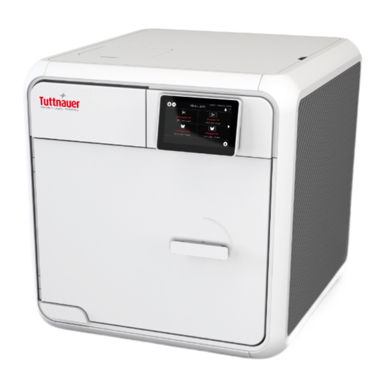
4. Depiction of System Parts 4.1 Front View Table 8 - Front View Description Description Touch screen Chamber ON/OFF switch Door switches Chamber Door Air filter Mineral-free water reservoir Door Gasket opening Mineral-free (left) and waste Door Handle water (right) reservoir drains Page 19... -
Page 27: Rear View
4.2 Rear View Table 9 - Rear View Description Description USB ports Waste outlet Mineral-free inlet (available in LAN socket AMS10-120-W-T) Cut-off Thermostat Safety valve Circuit breaker on off Aeration Ventilation opening switch Power socket Mind the Power socket. Keep it and its vicinity dry. Danger of electrocution. -
Page 28: Installation Instructions
5. Installation Instructions 5.1 Lifting and Carrying Cautions! Before moving the autoclave, make sure that the electric cord is disconnected from the power, and there is no pressure in the chamber. Drain the water from the reservoir (see Draining the Reservoirs) Do not drop the device! To avoid injuries, lifting and carrying should be done with at least two people or by using a fork-lift or any other mechanical aid. -
Page 29: Connections To Utility Supplies
104ºF(40ºC), it is preferable not to exceed 86 ºF (30ºC). 8. Check and verify that the ambient relative humidity does not exceed 9. The operational altitude shall not be over 13123 ft (4000 meters). 10. Ambient pressure shall not be lower than 8.8 psi (60.5 KPa) (if the altitude and temperature are kept in the manufacturer's instructed ranges above, and no forced extreme negative pressure is applied near the autoclave, then ambient pressure of 8.8 psi (60.5 KPa) or... -
Page 30: Initial Operation Of The Device
5.5 Initial Operation of the Device Note: Remove all packaging material before turning ON the device (see below). 1. Plug the power cord into the power socket. Mind the Power socket. Keep it and its vicinity dry. Danger of electrocution. Warning! 2. - Page 31 and then. 3. Turn on the ON/ OFF Switch mounted on the bottom left side of the front panel (see the front view). 4. When you turn on the autoclave, it will automatically warm up. Warning! Be careful the surfaces may be hot! 5.
-
Page 32: Before Starting The Autoclave
5.6 Before starting the Autoclave Before starting the autoclave we recommend that you check the following: 1. In the Quick Option screen, press the Info option. 2. Select the Version information. 3. The Version information is displayed. For an example, see below: Page 25... - Page 33 4. Press on the to return to the Info screen. 5. Select the Play tutorial option to watch the T-EDGE 10 Instructional Video 6. The T-EDGE 10 Instructional Video can be accessed in the link below: https://tuttnauer.com/t-edge10/en/video/how-to Page 26...
-
Page 34: Pre-Sterilization Cleaning And Disinfection Of Instruments And Their Loading Into The Device
6. Pre-sterilization Cleaning and Disinfection of Instruments and their Loading into the Device Instruments should not be loaded into the autoclave to be sterilized unless Steam Sterilization is instructed in their User Manual. The instructed Steam Sterilization Program Caution! should be verified against the programs available in this autoclave. - Page 35 Clean instruments immediately after use to remove any residue. It is recommended that all instruments be ultrasonically cleaned using Tuttnauer’s Clean & Simple enzymatic cleaning tablets or other suitable solution. After cleaning, rinse instruments under tap water for 30 seconds and pat or air dry to remove residual minerals.
- Page 36 penetration and promote drying, such as autoclave bag, autoclave paper, or muslin towels. When loading pouches on the tray, put them with paper side up, nylon side towards the tray (see the figure below) Tubing should be rinsed after cleaning. When placed in the tray, make sure that both ends of the tubing are open and there are no sharp bends or twists.
- Page 37 carbon steel and stainless steel. When these two metals come into contact with each other electrolysis occurs that breaks down the metal. The best solution is to separately wrap the carbon steel instrument to insulate it from other instruments on the tray and the tray itself. Page 30...
-
Page 38: Operating Instructions
7. Operating Instructions The following are the operation instructions. 7.1 Turning on the Device Plug the power cord into the socket on the rear panel of the autoclave (see the rear view) and into the wall outlet. Turn ON the semi-automatic ON/ OFF bottom Switch located on the rear panel of the autoclave (see the rear view). - Page 39 A general alarm symbol will appear. Proper Water level icon appears when the water reservoir is properly filled. (See the filling procedure in section 7.3 and Draining the Reservoir procedure in section 8.11). The water level icon appears when the water level in the reservoir is full. (See the filling procedure in section 7.3 and Draining the Reservoir procedure in section 8.11).
-
Page 40: Filling Water In The Reservoir
Caution! Before filling the reservoir, verify that the autoclave is idle and there is no pressure in the chamber. 7.3 Filling water in the reservoir Note: Use only water having the characteristics stated in Water Quality. Using tap water will clog the system and invalidate the manufacturer’s guarantee. -
Page 41: See The Requirements Concerning Water Quality, In Section
The screen below displays a full clean water tank. 7.4 See the requirements concerning Water Quality, in Section 1.12 Page 34... -
Page 42: Setting Date And Time
7.5 Setting Date and Time Note: The Initial log-in including setting of drying time as well as other initial parameters will be performed only by a qualified technician upon installation On the main screen, press the menu symbol to open the Quick Option screen. ... -
Page 43: Class S And Class B
Class B in the sterilization of hollow instruments. The following tables provide: Table A for types of sterilization cycles Table B provides the T-EDGE 10, Class B sterilization programs. Table C provides the T-EDGE 10, Class S sterilization programs. Table A — Types of sterilization cycles... - Page 44 Table B — Class B: sterilization cycles Cycle Name Sterilization Temp. Pre / Post Vac Unwrapped Instr. 273F 273°F Pre / Post Vac Wrapped Pouches 273F 273°F Pre / Post Vac Unwrapped Delicate 250F 250°F Pre / Post Vac Wrapped Delicate 250F 250°F Chamber Clean Bowie and Dick...
-
Page 45: Setting Class S And Class B
7.7 Setting Class S and Class B Your autoclave contains Class S as a standard. If you (the customer) would like to upgrade your system to a Class B, please contact Tuttnauer USA representatives or your dealer. Tuttnauer will ask you for the autoclave serial number. - Page 46 4. Enter Password. 5. Click on 6. A Class Settings message will appear confirming the action completed successfully. 7. Press to complete conversion. The autoclave is now converted to Class B and the screens displayed will have a Class B identification. Page 39...
- Page 47 Note: The Class B sign is on the screen header. The entire autoclave is now in Class B system, a sample of the screens after the conversion to Class B, are shown below: Page 40...
- Page 48 Note: It is possible to switch back from Class B to Class S if desired, following the steps above, by selecting S in step 3 above instead of S&B. Entering the code password is required. Page 41...
-
Page 49: Control Panel
8. Control Panel The display is a graphic Touch screen LCD panel used to display the autoclave current status, any Operational or Error Messages and for operating the machine. Image 1: Home screen –Program Select Screen This screen will be presented when the autoclave is switched on: Additional programs are accessible by paging using the side arrows: Page 42... -
Page 50: Home Screen Description And Functions
8.1 Home screen Description and Functions Table 10 - Screen description and functions Icon Name Description Home icon Immediate use only Menu Menu selection icon Exposed Unwrapped 273°F load Unwrapped 273F program Pressure Momentary Pressure in the chamber Momentary temperature in the Temperature chamber Load no. - Page 51 Icon Name Description Wrapped Delicate Wrapped Delicate 250°F load 250F program Warnings It indicate the Alerts Unwrapped Unwrapped Delicate 250°F program Delicate 250F Paging backward to the previous Side arrow left programs periodic testing as referred to in ISO Bowie and Dick 17665-1.See the screen in the top Test next page...
-
Page 52: Opening The Device Door
8.2 Opening the Device Door This machine is equipped with an electronic door lock. The door is locked when either the system is running a sterilization cycle, or there is pressure in the chamber, or the power is off. If you need to open the door after cycle completes, press the confirm button: Showing Class S In any case, if the door is not locked, it can be opened as illustrated below. -
Page 53: Starting A Cycle
8.3 Starting a Cycle It is recommended to perform B&D test cycle at the beginning of each working day. 1. Before each cycle, check visually that the gasket is intact, not loose and clean. 2. Load the autoclave properly (see chapter 6). 3. - Page 54 5. The next screen will prompt the selected program information. 6. Close the door by both: Pushing the door gently; Turning the handle clockwise while pushing the door until it comes to the closed position, then releasing the handle. When the door is closed, the open-door symbol is replaced with the closed-door symbol 8.
- Page 55 Note: For the results of the cycle, see description in section 8.5 Page 48...
-
Page 56: Virus Protect Program
8.4 Virus Protect program The Virus Protect is a program that eliminates viruses and is performed prior to a sterilization cycle. Note: The Virus Protect is not for use for Textile and Porous programs. 1. Select from a sterilization cycle, the Virus Protect option. 2. - Page 57 Note: If the Virus Protect program fails, the confirmation message below appears. After pressing on OK in this message, the system will release air outside of the autoclave. Page 50...
-
Page 58: Available Sterilization Programs And Test Programs
8.5 Available Sterilization Programs and Test Programs 8.5.1 List of available Sterilization and Test Programs CLASS B *Remark: The cycle time reported is 2.2 lbs (1kg) Solid, Warm Start Notes: The Unwrapped sterilization program can be used for sterilizing lumen device of no longer than 9"... - Page 59 8.5.2 List of available Sterilization and Test Programs CLASS S *Remark: The cycle time reported is 2.2 lbs (1kg) Solid, Warm Start 8.5.3 Maximum Load Weight per Load type Table 11 - Maximum Load Weights Load type Maximum Load Weight Suitable for programs Textile, porous ~3 lbs (1.5kg)
- Page 60 8.5.4 Description of the Sterilization Cycle Stages Air-removal stage: Pre vacuum pulses are performed. For wrapped cycles, there are 2-3 pulses and the vacuum are deeper. Heating stage: steam is inserted into the chamber until the sterilization temperature is reached Sterilization: sterilization temperature is maintained constant during the sterilization time.
-
Page 61: Cycle Succeeded / Cycle Failed Notifications And Follow-On
8.6 Cycle Succeeded / Cycle Failed Notifications and Follow-on 8.6.1 Cycle Succeeded When the cycle has ended successfully, the following "Successful" message is displayed: Push the confirm button to confirm the "Successful" message. Proceed to chapter "Opening the door and Unloading". 8.6.2 Cycle Failed In the event of a failure at any stage, the exhaust valve will be opened to release pressure from the chamber, the message "Fail"... -
Page 62: Aborting A Cycle
Warning! The load has not completed a sterilization cycle; therefore, it is not sterile. Handle it as a contaminated load. Any failure means that the load is not sterile. 8.7 Aborting a cycle It is possible to stop the cycle while the autoclave is operating. Press the Stop button at any stage (except exhaust) of the process to stop the operation. - Page 63 with an error message explaining the reason for the failure. An alternating buzzer signal will sound to notify the user. Press the button to confirm the displayed message. Warning! The load has not completed the cycle; therefore, it is not sterile. Handle it as a contaminated load.
-
Page 64: Custom Programs
Custom programs are not FDA approved! Validation of the sterilized cycle is the user's responsibility. T-Edge 10 offers the user a customized program, adjusted in order to sterilize items that cannot be sterilized in any of the preceding default programs. -
Page 65: Cycles History
3. Press to begin the customized cycle. 8.9 Cycles history The Cycles history menu enables printing a specific cycle. On the Quick Option screen, press the Settings icon , then browse to Advanced options / Handle cycles / Cycles history The following screen is displayed with the status of the cycle. - Page 66 Press to receive the entire printout of the selected cycle history. Page 59...
-
Page 67: Opening The Door And Unloading
8.10 Opening the door and Unloading 1. Push the button to confirm the "Successful" or the "error" message to unlock the door. 2. Open the door. Caution! Open the door a little to release the steam from the chamber. Only after the steam escaped, open the door widely. -
Page 68: Checking Waste Water Level
Warning! The sterility of the instruments processed in unwrapped cycles cannot be maintained if exposed to non-sterile environment. 8.11 Checking Waste Water Level When the waste water level is high, the general alarm symbol will appear. A relevant text alarm will appear in the alarms list. This situation is normal, but the operator cannot run a new cycle before draining the waste water reservoir (see Draining the Reservoirs in section 8.11). - Page 69 2. Put the other end of the hose into a drain bucket. 3. Insert part (5) into valve (3) and press it until you hear a click. The drain valve opens immediately. 4. When the water reservoir is empty, press part (4). Item (5) will pop out approx.
-
Page 70: Preventive And Scheduled Maintenance To Be Performed By The Operator
The instructions that follow can easily be carried out by the operating personnel and do not require a service technician. Should the need arise, technical assistance or a service technician can be requested by either calling your dealer or Tuttnauer U.S.A. 9.1 Daily Maintenance Caution! Make sure the autoclave is not hot before cleaning it. -
Page 71: Monthly Maintenance
9.3 Monthly Maintenance Caution! Make sure the autoclave is not hot before cleaning it. Turn the unit on momentarily to allow the door to be opened. Open the door, unplug the autoclave again, and proceed with cleaning. Clean and descale the chamber. If the autoclave is only used occasionally, drain the water from the mineral free water reservoir once a week, and refill with fresh mineral-free water or distilled water. - Page 72 the filter into place. Carefully Insert the new filter into the housing. Do not force. The AIR filter is located under the mounted under the cover (see below). 1. Unscrew the filter (see below). 2. Disconnect the pipe. 3. Connect the new filter. 4.
- Page 73 9.4.2 Cleaning the Drain Filter Make sure the autoclave is not hot before cleaning it Before proceeding, make sure that the electric cord is disconnected and there is no pressure in the Cautions! chamber. 1. Clean the drain filter every month. The DRAIN filter (1) is located inside the autoclave chamber at the bottom far end, to reach the filter open the autoclave chamber door, remove the tray (see below).
- Page 74 9.4.3 Replacing the Drain Filter Note:If after successive cleaning of the filter the result is not satisfactory proceed to the replacement of the drain filter (paragraph 9.4.3 below). Before proceeding, make sure that the electric cord is disconnected and there is no pressure in the chamber.
- Page 75 3. Unscrew the old Drain filter assembly, using M14 wrench. 4. Remove the old Drain filter assembly. 5. Screw the new Drain filter assembly, (P/N: CMT511-0048) to its place in the chamber bottom, tighten it with the M14 wrench. 6. Ensure the new filter is all the way in and seated properly. 7.
-
Page 76: Full List Of Informative Screen Display Symbols, Operating Messages, Error Messages And Troubleshooting
10. Full List of Informative Screen Display Symbols, Operating Messages, Error Messages and Troubleshooting The troubleshooting section is provided in order to enable the user to solve minor malfunctions, prior to contracting our service department. However, only technical personnel having proper qualifications and holding technical documentation (including a technician manual) and adequate information are authorized to serve the apparatus (See tables below). - Page 77 Required Symbol / Symbol / Message Action (if Message Description applicable) Good Water level (Waste water Informative symbol ---- tank) Full Water level (Waste water tank) Empty the waste water reservoir Alert Press to watch the alert description When cycle is selected it is ---- highlighted in red The "cycle succeeded"...
-
Page 78: Error Messages & Troubleshooting
10.2 Error messages & Troubleshooting Message Description In STBY stage, when Door switch (DI 1) “Door is Open” Open AND Door lock DO 2 is ON This message is displayed when any Temperature sensor or Pressure sensor is disconnected or out of range. "Analog Input Error"... - Page 79 Message Description cannot reach the required temperature, in the chamber, within the preset time. This message is displayed if Chamber Pressure drops below the sterilization "Low Pressure" pressure for 2 seconds during the sterilization stage. This message is displayed if Chamber Pressure raises 0.29 bar above "High Pressure"...
- Page 80 Message Description This message and symbol are displayed if an error occurs before sterilization cycle is completed. This message is displayed at the end of the cycle if the autoclave does not reach "Air Error" the atmospheric pressure after 10 minutes.
- Page 81 Message Description For prion cycle in manual water filling configuration, when the water tank is not full the “Start” button will not appear, Please fill water tank to full instead this error message will appear in for start the Active alarms screen. Prion cycle, in manual water filling and the water tank is not full If printer is not recognized an error will...
- Page 82 Message Description machine’s power switch Utility issue #3 – Please switch OFF and ON If I/O card disconnected during power on machine’s power switch Time jumped during the If main system clock changed during the cycle cycle No-user log-in If CFR-11 on and no user login Page 75...
-
Page 83: Tsc Printer Installation (Optional)
How to set, operate, use and maintain the printer after the first installation. 11.1 General printer information The printer(s) are optional and can be purchased/ordered from Tuttnauer by the customer, the printers can easily be installed and connected to the autoclave following the instructions below. - Page 84 The data is printed from the bottom up, beginning with the date and ending with "Cycle Ended". For an aborted cycle, "Cycle Failed" and the Error message are printed (refer to "Displayed Error Messages/Symbols"). The printer can also print labels when loaded with label roll and printer1 is selected.
- Page 85 Page 78...
-
Page 86: Important Safety Instructions
11.2 Important safety instructions 1. Read all the instructions and keep them for future use. 2. Follow all warnings and instructions on the product. 3. Disconnect the power plug from the AC outlet before cleaning or if fault happened. Do not use liquids or aerosol cleaners. Using a damp cloth is suitable for cleaning. -
Page 87: Installation For The First Time
11.3 Installation for the first time Unpacking the printer: 1. Carefully open the printer box (1) and remove the printer packing. 2. Place the printer (2) on the table, and remove the two tapes (3). 3. Remove the rest of the box content which includes USB communication cable (6), electrical power cable (7), CD (5), adapter (8), blue cable (9), and the printer instructions (4). -
Page 88: Loading Thermal Printer Paper Roll/ Label Roll
3. The top printer cover will lift as shown in the figure indicated by 2. 11.5 Loading thermal printer paper roll/ Label roll You can either load a thermal paper roll, or label roll on the printer roll compartment opening. You can also connect two printers to the autoclave, one loaded with thermal paper roll, and the second printer loaded with label roll. - Page 89 5. Insert the paper under the two paper guides (item 6) in figure 3 for the paper roll, pull the paper to extend it beyond the printer. Do the same for the label roll (item 6) figure 4. Page 82...
- Page 90 6. Push the printer cover down (fig 5) until you can hear a click indicating that the cover is connected to the printer bottom. Page 83...
-
Page 91: Connecting The Interface Cables To The Printer
11.6 Connecting the interface cables to the printer 1. Connect the adapter male (1) to the RC-232 Output Port blue cable female plug connection (2), tighten and secure the 2 screws (3) to the adapter. 2. Plug the adapter connected with the blue cable (8) to the printer adapter connection, Tighten the 2 screws (4). -
Page 92: Connecting Power And Interface Cables
11.7 Connecting power and interface cables 1. Connect the RC- 232 Output Port blue cable (6) to the back of the autoclave (4). 2. Connect the power cable plug connector of cable (6) coming from the printer to the electrical power source on the wall. 3. -
Page 93: Setting Printer Definitions
2. Switch on the printer power (1) at the printer back, keep pressing the finger in step 1 until the red light bulb in front start flashing. 3. Ensure that the green bulb lights. The printer will run and feed the roll until the end of calibration process, approximately half meter for paper roll, and 3 labels for label roll. - Page 94 2. Press on icon. 3. Enter administration password Select from drop down list. 4. Press Login Enter administration password Select from drop down list 5. Press on the quick option 6. Press on new 7. Press on system parameters Page 87...
- Page 95 8. Select for paper roll printer type 6. Select for label roll label 1. 9. If only the one printer is connected to the autoclave, local=0 or printer=1. The following table gives the various printer possibilities Printer Type Local Only paper roll 6 Only Label roll ...
-
Page 96: Chamber Clean Program
The tablet material is a combination of acidic salts and additional cleaning materials. Use one prepacked chamber clean tablet for all T-Edge10 Tuttnauer Autoclave models. Perform chamber clean every week. Chamber Clean Program-Icon Picture... -
Page 97: Chamber Clean Cleaning Procedure
12.2 Chamber clean Cleaning procedure Important The Chamber Clean cleaning program for class B and S for T-Edge10 autoclaves is described below: The chamber must be cold. 1. All steps in this procedure must be completed without interruption. 2. Open the autoclave chamber door. 3. - Page 98 8. Chamber Clean Program-Manual fill clean water tank. To fill water in the reservoir lift up the water reservoir cover and fill with clean water (see below). 9. Chamber Clean Program-Water tank clean & waste 10. Select Chamber Clean Program Page 91...
- Page 99 11. Chamber Clean Program -Start Cycle 12. Chamber Clean Program-Water tank alarm 13. Chamber Clean Program -Set manual mode fill clean water tank Page 92...
- Page 100 14. Please fill water tank to full for start.Chamber Clean Program- Alarm water fill before start, 15. Chamber clean program Stage Cleaning-insert water The chamber clean process last 45 minutes The warming up to 176ºF and hold for 10 minutes at 176ºF, (This stage uses 500ml of water from the clean water reservoir).
- Page 101 16. Chamber clean program Stage Cleaning-keep 17. After 45 minutes the chamber clean process is completed, the chamber is clean, and the following screen is displayed. Chamber Clean Program-cycle confirm by operator Page 94...
-
Page 102: Factory Codes For End User
13. Factory Codes for end user Notice: Please, find below Factory Codes for end user. These codes are similar to all T-Edge 10 machines from version 1.0. Level 1 Factory Code 010 7N613IOJT6 Admin - for User Manual Level 1 Factory Code 011 4YFBH5G597 Admin - for User Manual Level 1 Factory Code ... - Page 103 Level 1 Factory Code 037 RGQHB6D4R7 Admin - for User Manual Level 1 Factory Code 038 APZJ5F1IT3 Admin - for User Manual Level 1 Factory Code 039 93VTGY2Q6C Admin - for User Manual Level 1 Factory Code 040 KJCLC48NKH Admin - for User Manual Level 1 Factory Code ...
- Page 104 Cat. No. MAN205-0502015EN Rev.H COPYRIGHT ©...
Need help?
Do you have a question about the T-Edge 10 and is the answer not in the manual?
Questions and answers