Table of Contents
Advertisement
Quick Links
Advertisement
Table of Contents

Subscribe to Our Youtube Channel
Related Manuals for MRC Explorer-9000


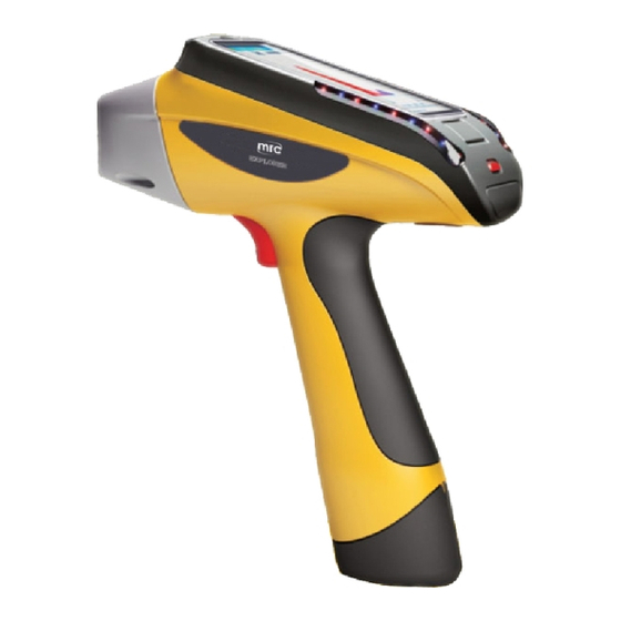
Summary of Contents for MRC Explorer-9000
- Page 1 Explorer-9000 User Manual...
-
Page 2: Table Of Contents
Contents 1. Product Overview........................... 1 1.1 Introduction..........................1 1.2 Applications..........................1 1.3 Advantages..........................1 1.4 Unpacking..........................1 2. Structure and Principle........................4 2.1 Instrument Overview......................4 2.1.1 Front View........................4 2.1.2 Left view........................4 2.1.3 Right view........................5 2.1.4 Front view........................6 2.1.5 Rear view........................6 2.2 Working Principle........................ - Page 3 5.5 Setup............................19 6. Sample measurement........................21 6.1 Initialize..........................21 6.2 Test............................22 6.3 Result analysis........................22 6.4 Print............................23 7. Care and Maintenance......................... 25 7.1 Daily Maintenance........................ 25 7.2 Periodic Maintenance......................25 7.3 Storage..........................25 7.4 Transportation........................25 8. Safety.............................. 26 9.
-
Page 4: Product Overview
This manual describes the portable Explorer series spectrometers manufactured by MRC.,Ltd Explorer portable series include harmful elements analyzer Explorer-3000, alloy analyzer Explorer- 5000, mineral analyzer Explorer-7000, soil heavy-metal analyzer Explorer-9000,etc.( XRF -X Ray Fluorescence- refers to X-ray fluorescence analysis). This manual takes Explorer 9000 for example Applications 1.2... -
Page 5: Unpacking
Equipped with a wide-voltage AC charger or car-loaded charger ensure test at anytime, anywhere. Warning indicator system. Powered, the green light is on; testing,the red light flashes to prevent error. The instrument is of waterproof, dustproof and works continuously in an environment of high temperature and high humidity. - Page 6 ;Adapter; ②TF reader; ③EXPLORER-9000; ④Mini USB cable; ⑤ Test membrane ① Charger; ⑦ Car-loaded power cord; ⑧Car-loaded triple ⑨ Radiation shield; ⑩ Rechargeable battery × 2; ⑪ Power cord; ⑫ Bag Fig.1-4 Any discrepancies with the product packing list, please contact the nearest MRC office or an authorized service cente.
-
Page 7: Structure And Principle
Structure and Principle 2.1 Instrument Overview 2.1.1 Front View ①PDA; ②Radiation Indicator; ③Power Indicator; ④External power port; ⑤ Power switch; ⑥ PDA rotation axis Fig 2-1 1) PDA - the embedded PDA installed with the dedicated X-ray fluorescence analytical software is used for instrument control,data processing and result display. -
Page 8: Right View
①TF Card Slot ②Mini USB Port ③Power and Charging Indicator ④Radiation Indicator ⑤Trigger ⑥Battery Fig.2-2 2.1.3 Right view ①Power & Radiation Indicator Fig.2-3 Radiation Indicator - when HV power is applied on the X-ray tube, the radiation indicator flashes red. Otherwise, constantly green. -
Page 9: Front View
2.1.4 Front view ①Test window Fig. 2-4 Test window: where sample is placed 2.1.5 Rear view ①Power Port②HV lock ③Buckle Fig. 2-5 1) Power Port - adapter power port, for powering the instrument. 2) HV lock-unlocked,HV works properly;lock,HV is in an inactive state. 3) Buckle- for external PDA touch pen and security strap (to avoid instrument falling when testing). -
Page 10: System Components
XRF principle: the atoms illuminated by high-energy X-ray emit X-ray spectra with a certain characteristics, the wavelength of which is only related to the atomic number of element, not X-ray excitation energy. Therefore, by determine the wavelength, we find what contained in the sample and start the qualitative analysis;... -
Page 11: Technical Specifications
Technical Specifications 3.1 Standard configuration 1) AMP and digital multi-channel system 2) Power and control system 3) Embedded PDA 4) Dedicated XRF analytical software(PDA version) 5) Laboratory test bracket (optional) 6) 110V/220V universal adapter 7) 2× 9000mAh li-ion battery, 1 li-ion charger(27000mAh large-capacity battery is optional) 8) Large-capacity TF storage card and TF reader 9) Anti-shock, anti-pressure, water-proof lockable portable case 3.2 Specification... - Page 12 Video HD CMOS camera DC9V 12W Max (working) Power 8W Max (standby) Consumption 2W Max (sleep) Chargeable li-ion battery, 9000mAH, 12 hours continuous running Power Source 110V/220V universal adapter for AC power DC charger: car charger Charger AC charger: 110/220V, 50/60HZ Monitor Transflective LCD touch screen (resolution 1080×720) Collimator and...
-
Page 13: Basic Operations
Basic operations 4.1 Battery 4.1.1 Assembly Take the instrument out of the packing case. Insert the battery into the handle of the instrument as below. Fig.4-1 Fig.4-2 4.1.2 Charging To charge the battery when out of power: 1)Take out the battery charger. - Page 14 Fig.4-3 2) Insert the battery Fig. 4-4 3) Connect the charger and adapter, and connect to the utility power to charge power (red light is on). ① To utility power socket (AC 110 / 220V) Fig.4-5...
-
Page 15: Use Of Adapter
4.2 Use of adapter Adapter is optional for powering the instrument,connected as below. ① To utility power socket (AC 110 / 220V) Fig.4-6 For security, be sure to use the supplied adapter and battery charger. Using a different power cord or battery charger could cause malfunctions or danger. 4.3 ON/OFF Before turn on the instrument, please make sure the instrument has been properly connected to battery or A/C adapter. -
Page 16: Conditions
NOTE: Gently press the power button. Do not force too much to avoid damaging the button. 4.4 Conditions 1) Ambient temperature& humidity requirements: Operating temperature: -20℃~ + 50℃ Operating humidity: ≤90% (non-condensing) 2) Keep the installation, use environment clean to prevent corrosive gas; 3) Prevent static damage and strong electromagnetic interference on the instrument. -
Page 17: Sample Handling
We sometimes intentionally add some element into the sample as an internal standard, which is known as internal standard method. 4.6 Sample handling You can measure directly by placing the nosepiece near the sample during mobile operation (ie, real-time mobile detection by holding the instrument in hand) But be careful not let the irregular barbed samples pierce the test film, which may cause damage to the beryllium window. -
Page 18: Software Introduction 5
Software introduction 5 Software interface appears after booting. Explorer-9000 software is fitted in the embedded PDA, . bind with WIN CE 7.0 platform, no need for installation 5.1 Power on Press switch button for 3 seconds to enter Starting interface, the interfaces switching as shown in Figure 5-1. - Page 19 Fig.5-3 Icon Function Display the remaining power View the current time, double-click to change the date and time Camera area, double click to control the camera switch Click Start Test button to test the samples Table 5-1 Date &Time settings is as shown in Figure 5-4, slide the Date & Time display column to change value, then click OK .
-
Page 20: Test Result
Fig. 5-4 5.3 Test result The Test results interface displays the test values (Figure 5-5 left),the users can view multiple test statistics(Figure 5-5 right), etc... Icon functions are listed in Table 5-2. Fig. 5-5 Icon Function Initialization button, click to start initialization... -
Page 21: Operation
Grade display area (displayed in alloy testing, not in environmental test) User mode main interface View multiple statistics Table 5-2 5.4 Operation As shown in Figure 5-6, the module contains open spectrum, history, export report, database switching and Bluetooth printing functions, listed in Table 5-3. Fig. -
Page 22: Setup
Bluetooth print: print the latest measurement result, or take out the spectrum and print the results. Table 5-3 Fig. 5-7 Fig. 5-8 Fig. 5-9 Fig. 5-10 5.5 Setup Start routine functional test in the Test interface (Figure 5-11) , such as sample name,test... - Page 23 times,interface settings and language settings,etc... Detailed info. is listed in Table 5-4 Fig.5-11 Fig.5-12 Icon Function Pre-test: change the test time, times,etc.. Interface settings: rotation,correction. Trigger mode: long-press to test, release to stop,or press the switch to turn on/off, or disabled Voice: select the appropriate language Table 5-4...
-
Page 24: Sample Measurement
Sample measurement 6.1 Initialize Generally, start the initialization for the first use of the instrument or the initialization conditions are changed. Enter Test Results (Fig.6-1)-> click ,the system initialization takes 3-10 seconds (Fig. 6-2), please be patient, pop-up Initialization succeed after the initialization(Fig. 6-3). If initialization fails, prompt Initialization fails. -
Page 25: Test
6.2 Test 1. Enter the user mode after boot. Put the sample in the test window, click Fig.6-4 left is schematic of the measurement interface, the right is schematic of the measurement results. If start the test with no sample, the instrument will remind you Place the sample. Fig. -
Page 26: Print
Fig.6-5 6.4 Print Bluetooth-print the latest measurement result,or take out the spectrum and print the results. First start the Bluetooth printer, as shown in Figure 6-6, push the switch button in the middle to start it. Fig.6-6 Fig.6-7 Fig.6-8... - Page 27 Fig.6-9 Fig.6-10 Fig.6-11 Enter Operation interface, select Bluetooth Print->Search as shown in Figure 6-7. Search the Bluetooth printer, as shown in Figure 6-8 left. Select the printer name,click Connect as shown in Figure 6-9, connect succeed is as shown in Figure 6-10 . Select Print to print the corresponding report as shown in Figure 6-11.
-
Page 28: Care And Maintenance
Care and Maintenance 7.1 Daily Maintenance XRF analyzers are precision instruments which require close attention to the maintenance. Here are some suggestions to help you prolong the service life. The instrument should be operated and kept by the specialized personnel. Any other person cannot access, operate or move the instrument without permission. -
Page 29: Safety
If there is smoke, or unusual noise, immediately turn the main power switch OFF, disconnect the power cord from the power outlet, and then call your local authorized MRC dealer. Using the instrument in this state may cause a fire or electrical shock. Also, avoid placing objects around the... -
Page 30: Troubleshooting
Correction: Immediately turn off the main power, plug out the battery from the instrument handle and disconnect the power cord from the power outlet. Then call your local authorized MRC dealer or service center Others 9.3... -
Page 31: Appendix
Appendix Packing list Category Item Quan. Note X-ray Spectrometer Explorer-9000 Documentation Warranty / Certificate card CD-ROM Lithium Battery 9000mAh Adapter Power Cord Battery Charger Mini USB Extension Cable Standard TF Card Card Reader PDA Stylus 3-Way Car Cigarette Lighter Socket Splitter...
Need help?
Do you have a question about the Explorer-9000 and is the answer not in the manual?
Questions and answers