Advertisement
Quick Links
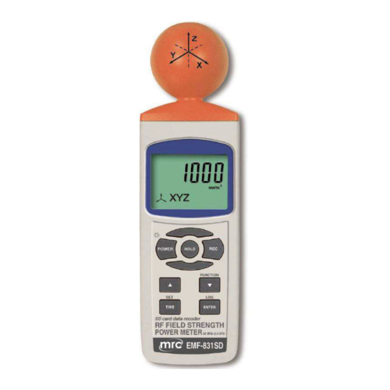
SD card real time datalogger, RS232/USB
RF EMF Strength Meter
Model : EMF-831SD
Your purchase of this
Personal RF EMF
Strength Meter
with SD CARD
DATALOGGER marks a
step forward for you
into the field of
precision measurement.
Although this METER is
a complex and delicate
instrument, its durable
structure will allow
many years of use if
proper operating
techniques are
developed. Please read
the following
instructions carefully
and always keep this
manual within easy
reach.
OPERATION MANUAL
3, Hagavish st. Israel 58817 Tel: 972 3 5595252, Fax: 972 3 5594529
mrc@mrclab.com
MRC. 2.20
Advertisement

Subscribe to Our Youtube Channel
Related Manuals for MRC EMF-831SD


Summary of Contents for MRC EMF-831SD
- Page 1 SD card real time datalogger, RS232/USB RF EMF Strength Meter Model : EMF-831SD Your purchase of this Personal RF EMF Strength Meter with SD CARD DATALOGGER marks a step forward for you into the field of precision measurement. Although this METER is...
- Page 2 TABLE OF CONTENTS 1. FEATURES..........................2. SPECIFICATIONS.......................... 3. FRONT PANEL DESCRIPTION..................... 4. MEASURING PROCEDURE....................4-1 RF EMF Strength Function selection and measurement ............4-2 Data Hold........................4-3 Data Record ( Max., Min. reading )..................5. DATALOGGER..........................5-1 Preparation before execute datalogger function..............
- Page 3 1. FEATURES * Measurements range : 50MHz to 3.5GHz. * For electromagnetic field strength measurement including mobile phone base station antenna radiation, RF power measurement for transmitters, wireless LAN (Wi-Fi) detection/installation, wireless communication applications (CW, TDMA, GSM, DECT) and microwave leakage * The meter is a broadband device for monitoring high-frequency radiation in the specific frequency ranges of 900MHz, 1800MHz, and 2.7GHz.
- Page 4 2. SPECIFICATIONS 2-1 General Specifications Circuit Custom one-chip of microprocessor LSI circuit. Display LCD size : 52 mm x 30 mm Measurement Digital, triaxial measurement. method Sensor type Electrical-field sensors resolution 0.1mV/m, 0.1uA/m, 0.1uW/m^2, 0.001uW/cm^2 Range autorange Datalogger Auto 2 to 3600 seconds Sampling Time Setting range Sampling time can set to 1 second,...
- Page 5 Over Indication Show " - - - - ". Data Hold Freeze the display reading. Memory Recall Maximum & Minimum value. Sampling Time Approx. 1 second. of Display Data Output RS 232/USB PC computer interface. Connect the optional RS232 cable UPCB-02 will get the RS232 plug.
- Page 6 2-2 Electrical Specifications (23±5 , 25% ~ 75 % RH) ℃ Frequency range: 50 MHz to 3.5GHz Specified measurement range: 20 mV/m to 25.0 V/m CW signal (f > 50MHz): 53 uA/m2 to 66.3mA/m 1 uW/m2 to 7.15W/m2 0 uW/cm2 to 0.715mW/cm2 Units mV/m, V/m, µA/m, mA/m, µW/m2, mW/m2, W/m2, µW/cm2, mW/cm2...
- Page 7 3. FRONT PANEL DESCRIPTION Fig. 1 3-1 Display. 3-15 Battery compartment/Cover 3-2 Power Button 3-16 Tripod Fix Nut 3-3 Hold Button 3-17 RF EMF detect seneor 3-4 REC Button 3-5 ▲ Button ( UNIT Button) 3-6 ▼ Button ( X,Y,Z,XYZ Function Button ) 3-7 Time Button (SET Button ) 3-8 Enter Button ( Logger Button) 3-9 SD card socket...
- Page 8 4. MEASURING PROCEDURE E-field sensors The 3-channel sensor is located at the top of the meter. The three voltages generated by the sensor are fed back to the meter. The measurement of the field is done by moving the aerial of the sensor in the desired measured environment.
- Page 9 3. Pay special attention to measuring the neighboring vicinity for possible radiation sources. Apart from active sources, those components connected to a source may also act as radiators. For example, the cables used in diathermy equipment may also radiate electromagnetic energy. Note that metallic objects within the field may locally concentrate or amplify the field from a distant source.
- Page 10 5. DATALOGGER 5-1 Preparation before execute datalogger function a. Insert the SD card Prepare a " SD memory card " ( 1 G to 16 G, optional ), insert the SD card into the " SD card socket " ( 3-9, Fig. 1). The front panel of the SD card should face against the the down case.
- Page 11 5-2 Auto Datalogger ( Set sampling time 1 second ) ≧ a. Start the datalogger Press the " LOG Button ( 3-8, Fig. 1 ) > 1.5 seconds continuously, the LCD will show the text of " LOGGER " indecator and flashing per second, at the same time the measuring data along the time information will be saved into the memory circuit.
- Page 12 5-3 Manual Datalogger ( Set sampling time = 0 second ) a. Set sampling time is to 0 second Press the " LOG Button ( 3-8, Fig. 1 )>1.5 second, the LCD will show the indecator " LOGGER " and " Position no. " symbol then press the "...
- Page 13 5-5 SD Card Data structure 1) When the SD card is used into the meter, the SD card When the first time, the SD card is used into the meter, the SD card will generate a folder : EMF01 2) If the first time to execute the Datalogger, under the route EMF01\, will generate a new file name EMF01001.XLS.
- Page 14 6. Saving data from the SD card to the computer ( EXCEL software ) 1) After execute the Data Logger function, take away the SD card out from the " SD card socket " ( 3-9, Fig. 1 ). 2) Plug in the SD card into the Computer's SD card slot ( if your computer build in this installation ) or insert the SD card into the "...
- Page 15 EXCEL graphic screen (for example )
- Page 16 7. ADVANCED SETTING Under do not execute the Datalogger function, press the " SET Button " ( 3-7, Fig. 1 ) continuously at least 1.5 seconds will enter the " Advanced Setting " mode. then press the " SET Button " ( 3-7, Fig. 1 ) once a while display will show : Set clock time ( Year/Month/Date, Hour/Minute/Second ) SET DATE..
- Page 17 Remark : After the time value is setting, the internal clock will run precisely even Power off if the battery is under normal condition ( No low battery power ). 7-2 Set sampling time ( Seconds ) When the lcd display show " SP-t " ,DD/s led indicator will light 1) Use the "...
- Page 18 YES - Meter's beep sound will be ON with default. no - Meter's beep sound will be OFF with default. 2) After select the led displary show " YES " or " no ", press the " Enter Button " ( 3-8, Fig. 1 ) will save the setting function with default.
- Page 19 2) If select the lcd display show " YES ", press the " Enter Button " ( 3-8, Fig. 1 ) once , the Display will show text " Enter " and " YES " to Flashing interaction , if make sure to do the SD memory card format , then press "...
- Page 20 8. POWER SUPPLY from DC ADAPTER The meter also can supply the power supply from the DC 9V Power Adapter ( optional ). Insert the plug of Power Adapter into " DC 9V Power Adapter Input Socket " ( 3-12, Fig. 1 ). 9.
- Page 21 Meter (9W 'D" Connector) Center Pin..........Pin 4 (3.5 mm jack plug) Ground/shield........... Pin 2 2.2 K resistor Pin 5 The 16 digits data stream will be displayed in the following format : D15 D14 D13 D12 D11 D10 D9 D8 D7 D6 D5 D4 D3 D2 D1 D0 Each digit indicates the following status : Start Word D12, D11...
- Page 22 RS232 FORMAT : 9600, N, 8, 1 Baud rate 9600 Parity No parity Data bit no. 8 Data bits Stop bit 1 Stop bit 11. PATENT The meter ( SD card structure ) already get patent or patent pending in following countries : Germany Nr.
Need help?
Do you have a question about the EMF-831SD and is the answer not in the manual?
Questions and answers