Advertisement
Quick Links
G ( Gauss), mT ( milli Tesla ), USB/RS232
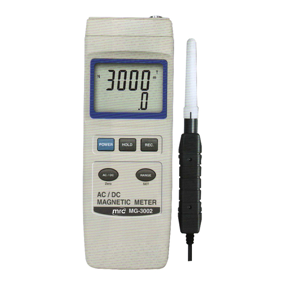
AC/DC MAGNETIC METER
Model : MG-3002
OPERATION MANUAL
3, Hagavish st. Israel 58817 Tel: 972 3 5595252, Fax: 972 3 5594529
Your
purchase
AC/DC MAGNETIC METER
marks a step forward for
you
into
precision measurement.
Although this METER is a
complex
instrument,
structure will allow many
years of use if proper
operating techniques are
developed. Please read the
following
carefully and always keep
this manual within easy
reach.
mrc@mrclab.com
MRC. 5.18
of
this
the
field
of
and
delicate
its
durable
instructions
Advertisement

Related Manuals for MRC MG-3002


Summary of Contents for MRC MG-3002
- Page 1 G ( Gauss), mT ( milli Tesla ), USB/RS232 AC/DC MAGNETIC METER Model : MG-3002 Your purchase this AC/DC MAGNETIC METER marks a step forward for into field precision measurement. Although this METER is a complex delicate instrument, durable structure will allow many...
-
Page 2: Table Of Contents
TABLE OF CONTENTS 1. FEATURES..............1 2. SPECIFICATIONS............2 3. FRONT PANEL DESCRIPTION........4 3-1 Display..............4 3-2 Power Button............4 3-3 Hold Button............4 3-4 REC Button............4 3-5 ZERO Button ............4 3-6 Mode Button ( DC, AC Button ), SET Button.... 4 3-7 Input socket............4 3-8 Probe Handle............ -
Page 3: Features
1. FEATURES * Wide range, general purpose magnetic measurement. for industrial, mechanical, material, electrical, laboratory field usage. * Unit : G ( Gauss ), mT ( milli Tesla ). * DC and AC magnetic field measurement * DC Range : 300.00 mT/3000.0 mT. AC Range : 150.00 mT/1500.0 mT. -
Page 4: Specifications
2. SPECIFICATIONS Circuit Custom one-chip of microprocessor LSI circuit. Display LCD size : 52 mm x 38 mm dual function LCD display. Measurement milli Tesla Unit Gauss Measurement Range 1 300.00 mT x 0.01 mT Range, DC Range 2 3,000.0 mT x 0.1 mT Range 1 3,000.0 G x 0.1 G Range 2 30,000 G x 1 G Measurement... - Page 5 Data Output RS 232/USB PC serial interface. * Connect the optional RS232 cable UPCB-02 will get the RS232 plug. * Connect the optional USB cable USB-01 will get the USB plug. Power Supply 006P DC 9V battery ( Alkaline or Heavy duty type ). DC 9V adapter input.
-
Page 6: Front Panel Description
3. FRONT PANEL DESCRIPTION Fig. 1 3-1 Display 3-2 Power Button 3-3 Hold Button 3-4 REC Button ( Enter Button ) 3-5 ZERO Button 3-6 Mode Button ( DC, AC Button ), SET Button 3-7 Input socket 3-8 Probe Handle 3-9 Probe Sensing Head 3-10 Probe Plug 3-11 Probe Head Cover... -
Page 7: Measuring Procedure
4. MEASURING PROCEDURE 4-1 AC/DC magnetic field measurement 1)Power ON the meter by pressing the " Power Button " ( 3-2, Fig. 1 ) once. 2)Press the " Mode Button " ( 3-6, Fig. 1 ) once , the Display will show the following screen in sequence : Under mT unit Under G unit N(S) - Page 8 3) Display indicator DC magnetic field measurement * The Display will show " N " or " S " indicator. * North pole : Display will show " N " indicator * South pole : Display will show " S " indicator AC magnetic field measurement * Display will show "...
-
Page 9: Data Hold
6)Zero adjustment : When power ON the meter, due to the environment interference, the display may show certain values ( not zero value), it is normal. * Before the measurement, fix the probe at the exact position, press the " ZERO Button " ( 3-5, Fig. 1 ) continuously at least two seconds until the display show "... - Page 10 b)Press the " REC Button " ( 3-4, Fig. 1 ) again, the " REC. MIN " symbol along with the minimum value will appear on the display. If intend to delete the minimum value, just press the " Hold Button " ( 3-3, Fig. 1 ) once, then the display will show the "...
- Page 11 5-1 Auto power OFF management When the lower display show " PoFF " 1)Use the " REC Button " ( 3-4, Fig. 1 ) to enter will enter into the setting of " Auto power off management ". Press the " Mode Button " ( 3-6, Fig. 1 ) once in sequence to select upper value to "...
-
Page 12: For The User
5-3 For the further calibration usage, not available for the user When the lower display show " CLr " This setting just for the further calibration usage, not available for the end user. 6. RS232 PC SERIAL INTERFACE The instrument has RS232 PC serial interface via a 3.5 mm terminal ( 3-12, Fig. -
Page 13: Battery Replacement
Each digit indicates the following status : Start Word = 02 D12 & Annunciator for Display mT = E3 G = B5 Polarity 0 = Positive 1 = Negative Decimal Point(DP), position from right to the left, 0 = No DP, 1= 1 DP, 2 = 2 DP, 3 = 3 DP D8 to D1 Display reading, D8 = MSD, D1 = LSD For example :... -
Page 14: System Reset
8. SYSTEM RESET If the meter happen the troubles such as : CPU system is hold ( for example, the key button can not be operated... ). Then make the system RESET will fix the problem. The system RESET procedures will be either following method : During the power on, use a pin to press the "...
Need help?
Do you have a question about the MG-3002 and is the answer not in the manual?
Questions and answers