Table of Contents
Advertisement
Quick Links
RF and LF measurement
RF Strength, LF Magnetic Fields/Electric Fields Meter
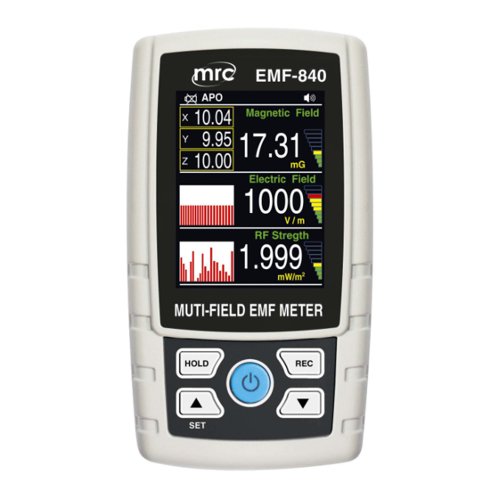
Multi-Field EMF Meter
Model : EMF-840
OPERATION MANUAL
PLEASE READ THIS MANUAL CAREFULLY BEFORE OPERATION
3, Hagavish st. Israel 58817 Tel: 972 3 5595252, Fax: 972 3 5594529
Your purchase of this Personal
Multi-Field EMF Meter Strength
Meter marks a step forward
for you into the field of precision
measurement. Although this
METER is a complex and
delicate instrument, its durable
structure will allow many years
of use if proper operating
techniques are developed.
Please read the following
instructions carefully and
always keep this manual
within easy reach.
mrc@mrclab.com
MRC. 3.20
Advertisement
Table of Contents

Related Manuals for MRC EMF-840


Summary of Contents for MRC EMF-840
- Page 1 RF and LF measurement RF Strength, LF Magnetic Fields/Electric Fields Meter Multi-Field EMF Meter Model : EMF-840 Your purchase of this Personal Multi-Field EMF Meter Strength Meter marks a step forward for you into the field of precision measurement. Although this...
-
Page 2: Table Of Contents
TABLE OF CONTENTS 1. FEATURES..........................2. SPECIFICATIONS........................3. FRONT PANEL DESCRIPTION..................... 4. MEASURING PROCEDURE....................4-1 Measurement LFMagnetic Fields/Electric Field, RF EMF Strength ....... 4-2 Data Hold........................4-3 Data Record ( Max., Min. reading )................. 4-4 LCD brightness select..................... 4-5 Sound Alert Table ...................... -
Page 3: Features
1. FEATURES * RF application : For electromagnetic field strength measurement including mobile phone base station antenna radiation, RF power measurement for transmitters, wireless LAN ( Wi-Fi ) detection/ installation, wireless communication applications ( CW, TDMA, GSM, DECT ) and microwave leakage. * RF power measurement Range/Resolution : Frequency range : 50 MHz to 3.5 GHz. -
Page 4: Specifications
2. SPECIFICATIONS 2-1 General Specifications Display LCD view size : 2.4" TFT LCD. Measurement EMF ( Electromagnetic field tester. ) Band width RF:50~3.5 MHz, LF: 50/60 Hz Number Axes Single Axis. Operating Max. 80% RH. Humidity Operating 0 to 50 ℃ ( 32 to 122 ℉ ) Temperature Over Input Indication of "- - - - "... - Page 5 2-2 Electrical Specifications (23±5 , 25% ~ 75 % RH) ℃ RF EMF tester METER Unit Range Resolution Absolute error 30.00mV/m ~ 11.00 V/m 0.001,0.01 , 0.1 1.0dB mV/m,V/m /cm2 0.02 ~ 32.09 µW/cm2 0.01 , 0.1 µW µW/m2,mW/m2 0.02 µW/m2 ~ 320.9 mW/m2 0.001,0.01 , 0.1 at 1 V/m &...
-
Page 6: Front Panel Description
3. FRONT PANEL DESCRIPTION Fig. 1 3-1 Display. 3-10 Wristlet 3-2 Power Button 3-11 Electric Field detector 3-3 Hold Button 3-12 RF detector 3-4 REC (Enter) Button 3-13 LF detector 3-5 ▲ Button ( SET Button) 3-6 ▼ Button 3-7 Tripod Fix Nut 3-8 Battery Cover Screws ( Logger Button) 3-9 Battery compartment/Cover... -
Page 7: Measuring Procedure
4. MEASURING PROCEDURE 4-1 MEASUREMENT 1) Turn on the meter by pressing the " Power Button " ( 3-2, Fig. 1 ) > 1.5 seconds continuously. * Pressing the " Power Button " ( 3-2, Fig. 1 ) continuously and > 1.5 seconds again will turn off the meter. - Page 8 remark: * If the meter is moved quickly, may be field strength values will be displayed which do not reflect the actual field conditions. Measurement Note: * Hold the meter at arm’s length. * during the measurement please keep the meter steady . * If the test field conditions are unknown, please Make several measurements at various locations in the work place or other areas of interest , this is particularly important.
-
Page 9: Data Hold
4-2 Data Hold During the measurement, press the " Hold Button " ( 3-3, Fig. 1 ) once will hold the measured value & the " HOLD Symbol " indicator will be light, Press the " Hold Button " once again will release the data hold function , ( 3-3, Fig. -
Page 10: Advanced Setting
5. ADVANCED SETTING Under do not execute the Datalogger function, press the " SET Button " ( 3-5, Fig. 1 ) continuously at least 1.5 seconds will enter the " Advanced Setting " mode. then press the " SET Button " ( 3-5, Fig. 1 ) once a while display will show : POFF.. -
Page 11: Set Beeper Sound On/Off
5-2 Set beeper sound ON/OFF When the " BEEPER SOUND " text is mark (white color) 1) Press "Enter(REC button)" into the setting function,then use the " ▲ Button" ( 3-5, Fig. 1 ) or " ▼ Button " ( 3-6, Fig. 1 ) to select the upper value to "... -
Page 12: Set Emf Unit
5-4 Set EMF UNIT When the " EMF UNIT " text is mark (white color) 1) Press "Enter(REC button)" into the setting function,then use the " ▲ Button" ( 3-5, Fig. 1 ) or " ▼ Button " ( 3-6, Fig. 1 ) to select the EMF unit to "... -
Page 13: Power Supply
6. POWER SUPPLY The meter power supply is DC 1.5 V battery UM4, AAA x 3 pcs 7. BATTERY REPLACEMENT 1) When the left corner of " Lobattery text " indicator is light, it is necessary to replace the battery. However, in-spec. measurement may still be made for several hours after low battery indicator appears before the instrument become inaccurate.
Need help?
Do you have a question about the EMF-840 and is the answer not in the manual?
Questions and answers