Table of Contents
Advertisement
Quick Links
Download this manual
See also:
Operator's Manual
Advertisement
Table of Contents

Subscribe to Our Youtube Channel
Related Manuals for Stoelting F112


Summary of Contents for Stoelting F112
- Page 1 Model E112/F112 OWNER’S MANUAL Manual No. 513613 Rev.2 August, 2007...
- Page 3 Stoelting Counter Model Gravity Freezer This manual provides basic information about the freezer. Instructions and suggestions are given covering its operation and care. The illustrations and specifications are not binding in detail. We reserve the right to make changes to the freezer without notice, and without incurring any obligation to modify or provide new parts for freezers built prior to date of change.
- Page 4 Safety Alert Symbol: This symbol Indicates danger, warning or caution. Attention is required in order to avoid serious per- sonal injury. The message that follows the symbol contains important information about safety. Signal Word: Signal words are distinctive words used throughout this manual that alert the reader to the existence and relative degree of a hazard.
-
Page 5: Table Of Contents
Section Description Description and Specifications Description ... 1 Specifications ... 2 Installation Instructions Safety Precautions ... 5 Shipment and Transit ... 5 Freezer Installation ... 5 Initial Set-Up and Operation Operator’s Safety Precautions ... 7 Operating Controls and Indicators ... 7 Sanitizing ... -
Page 7: Description And Specifications
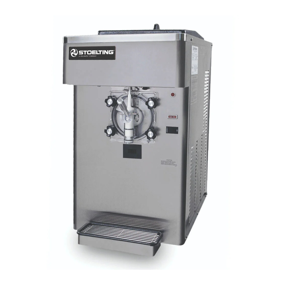
SECTION 1 DESCRIPTION AND SPECIFICATIONS 1.1 DESCRIPTION The Stoelting E112/F112 counter freezers are gravity fed. The freezers are equipped with fully automatic controls to provide a uniform product. They will operate with almost any type of shake or frozen beverage mix. This manual is... -
Page 8: Specifications
1.2 SPECIFICATIONS E112 F112 Figure 1-2 Freezer Specifications... - Page 9 35'' (88,9 cm) 36-1/2'' (92,7 cm) 215 lbs (97,5 kg) approximately 16A 6,000 Btu/hr 1/3 hp 12 GPH (45,42 liters) Model F112 Freezer with crate 17-1/4'' (43,7 cm) 29'' (73,7 cm) 33'' (83,7 cm) 44'' (111,7 cm) 30-1/4'' (76,7 cm)
-
Page 11: Installation Instructions
The F112 has a base gasket that must be installed. Separate the gasket and install it with the seam to the back. Make sure the angled side of the gasket is facing up. - Page 12 Connect the power cord to the proper power supply. The plug on the E112 is designed for 115 volt / 20 amp duty and the plug on the F112 is designed for 208 or 230 volt / 20 amp duty. Check the nameplate on your freezer for proper supply.
-
Page 13: Initial Set-Up And Operation
INITIAL SET-UP AND OPERATION 3.1 OPERATOR’S SAFETY PRECAUTIONS SAFE OPERATION IS NO ACCIDENT; observe these rules: Know the freezer. Read and understand the Operating Instructions. Notice all warning labels on the freezer. Wear proper clothing. Avoid loose fitting garments, and remove watches, rings or jewelry that could cause a serious accident. -
Page 14: Sanitizing
The autofill kit is for use with non- potentially hazardous food substances; non-dairy. Refer to Section 5-4 for Autofill options. Light Kit - Optional (E112 Part 2183800, F112 Part 2187102) The light kit is installed behind the header panel and illuminates a translucent header panel. -
Page 15: Freeze Down And Operation
Figure 3-2 Sanitizing hopper Place the switch in the CLEAN position. Check for leaks. Clean sides of hopper, mix inlet regulator and underside of hopper cover using a soft bristle brush dipped in the sanitizing solution (Refer to Figure 3-2). After five minutes, place a bucket under the spigot and open spigot to drain sanitizing solution. -
Page 16: Removing Mix From Freezer
3.6 REMOVING MIX FROM FREEZER To remove the mix from the freezer, refer to the following steps: If removing shake mix, pull the mix inlet regulator straight up and remove it from the hopper. Place the switch in the CLEAN position to rotate the auger. -
Page 17: Cleaning The Freezer Parts
Figure 3-6 Removing O-Ring Remove spigot body from the front door. Remove o-rings (2) from the spigot by first wiping off the lubricant using a clean paper towel. Then squeeze the o-ring upward with a dry cloth. When a loop is formed, roll the o-ring out of the groove (Refer to Figure 3-6). -
Page 18: Routine Cleaning
Do not use highly abrasive materials as they will mar the finish. 3.13 PREVENTIVE MAINTENANCE Stoelting recommends that a maintenance schedule be followed to keep the freezer clean and operating properly. CLEANING AND SANITIZING INFORMATION Special consideration is required when it comes to food safety and proper cleaning and sanitizing. - Page 19 SOIL MATERIALS ASSOCIATED WITH FROZEN DESSERT MACHINES MILKFAT/BUTTERFAT – As components of ice-cream/ frozen custard mix, these soils will accumulate on the interior surfaces of the machine and its parts. Fats are difficult to remove and help attribute to milkstone build-up. MILKSTONE –...
- Page 20 The condenser must be kept clean of dirt and grease. The F112 must have a minimum of 6” (15.2 cm) of ventilation on the right and left sides of the unit for free flow of air. The E112 must have 3”...
-
Page 21: Extended Storage
Figure 3-11 F112 Condenser Filter Removal F112 Air Cooled Condenser Cleaning Remove the Phillips head screws from the bottom of the right side panel, and then slide the panel down and out. To remove the condenser filter, grasp the top and pull off. -
Page 23: Troubleshooting
4.1 LIGHT INDICATORS The freezer has two lights that will alert the user if a problem occurs: an ADD MIX light and a Diagnostic Light. The ADD MIX light will flash to alert the operator to a low mix condition. It does so by monitoring the mix level in the hopper. - Page 24 4.2 TROUBLESHOOTING - CONTINUED PROBLEM POSSIBLE CAUSE 1. No vent space for free flow of cooling air. 2. Air temperature entering condenser is above 100°F. 3. Condenser is dirty. Product is too soft. 4. Consistency setting too soft. 5. Stabilizers in mix are broken down. 6.
-
Page 25: Replacement Parts
Decal - Wired According To 324584 Decal - Adequate Ventilation 3" 324686 Decal - Danger Automatic Start 324804 Decal - Domed Stoelting Swirl (Header Panel) 324852 Decal - Clean Condenser Filter 324853 Decal - Warmer / Colder 508048 Lubricant - Spline (2 oz Squeeze Tube) -
Page 26: Auger Shaft And Faceplate Parts
5.2 AUGER SHAFT AND FACEPLATE PARTS... - Page 27 5.2 AUGER SHAFT AND FACEPLATE PARTS - CONTINUED...
-
Page 28: Hopper Parts
Tray - Drain (Front) 744601 Tray - Drain (Rear) 1183955 O-Ring Kit 2183642 Mix Inlet Assembly 2183721 Mix Inlet Assembly 314466 695706 695707 695714 417006 E112 - 2183642 F112 - 2183721 624607 744281 Quantity E112 F112 1 (shake only) 1 (shake only) -
Page 29: Autofill Options
5.4 AUTOFILL OPTIONS The E112 and F112 freezers can easily be configured to use an Autofill System. The Autofill System provides a constant supply of non-dairy mix to the freezer. AUTOFILL KIT An autofill kit is needed to use an Autofill System. The kit includes a solenoid, tubing, and a new hopper cover (the F112 also includes a transformer). - Page 31 Stoelting, LLC warrants to the first user (the “Buyer”) that the freezer cylinders, hoppers, compressors, drive motors, speed reducers, augers and auger flights of Stoelting soft serve / shake freezers will be free from defects in materials and workmanship under normal use and proper maintenance appearing within five (5) years, and that all other...
Need help?
Do you have a question about the F112 and is the answer not in the manual?
Questions and answers