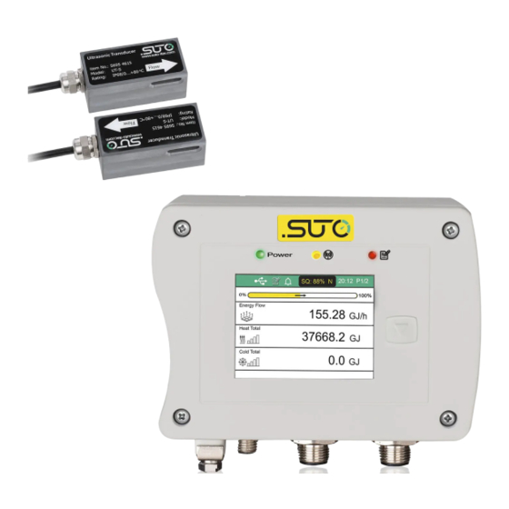
SUTO S461 Instruction And Operation Manual
Ultrasonic flow meter
Hide thumbs
Also See for S461:
- Instruction and operation manual (48 pages) ,
- Instruction and operation manual (60 pages)
Table of Contents
Advertisement
Quick Links
Advertisement
Table of Contents

Related Manuals for SUTO S461


Summary of Contents for SUTO S461
- Page 1 English Instruction and operation manual S461 Ultrasonic flow meter...
- Page 2 The device is destined exclusively for the described application. SUTO offers no guarantee for the suitability for any other purpose. SUTO is also not liable for consequential damage resulting from the delivery, capability or use of this device.
-
Page 3: Table Of Contents
7.1 Installing S461 main unit.............18 7.2 Electrical connection............19 7.2.1 M12 connection pins............19 7.2.2 Ethernet connection............21 7.2.3 M8 connection pins............23 7.3 Setting S461 by S4C-US App..........24 7.3.1 Installing S4C-US App ...........24 7.3.2 Scanning QR code ............24 7.3.3 Basic Settings...............25 7.3.4 Installation settings............27 7.4 Transducer Installation ............28... - Page 4 8.6 Logger settings..............36 9 System Functions..............37 9.1 Sensor info................37 9.2 Language................37 9.3 Logger status..............37 9.4 System log.................37 9.5 Wireless sensor connection ..........37 9.6 App version................37 10 Calibration................38 11 Maintenance................38 12 Disposal or waste..............38 13 Appendix – Modbus register table..........39 S461...
-
Page 5: Safety Instructions
• Do not exceed the permitted operating parameters. • Make sure the product is operated in its permitted limitations. Store and operate the product at the permitted temperature and pressure. • The product must be maintained and calibrated frequently, at least annually. S461... - Page 6 • Please make sure that the storage temperature of the device is between -10 ... +50°C. • Avoid direct UV and solar radiation during storage. • For the storage the humidity must be <90% with no condensation. S461...
-
Page 7: Registered Trademarks
2 Registered trademarks 2 Registered trademarks Trademark Trademark owner SUTO ® SUTO iTEC MODBUS ® Modbus Organization, Hopkinton, USA HART ® HART Communication Foundation, Austin, USA Android™, Google LLC Google Play S461... -
Page 8: Applications
• Oil, Diesel • Oil, Fuel • Water, distilled • Water, Sea • Others (please enter sonic speed) The S461 flow meter is mainly used in an industrial environment. It is not developed to be used in explosive areas. S461... -
Page 9: Features
• User friendly configuration through the dedicated smartphone App. • A wide range of pipe sizes from DN40 to DN1200. • Data analysis via the S4A software. • Through additional temperature sensor inputs S461 can be used as energy meter to monitor heat exchanger. • Bi-directional flow measurement. -
Page 10: Technical Data
0.5 °K Selectable units Metric: °C, Imperial: °F Measuring range -40 ... +130 °C Sensor Pt1000 Energy Flow Selectable units Metric: GJ/h, kJ/h, kcal/h Imperial: MBtu/h, Btu/h Energy Selectable units Metric: GJ, kJ, kcal, kWh, MWh Imperial: MBtu, Btu S461... -
Page 11: Signal And Interface
Data Logger Storage 8 Mio. values Material Main Casing PC + ABS Sensor UT-S: Industrial synthetic plastics UTH-S: Aluminum Miscellaneous Electrical connection 2 x M12 (4-pole): transducer 1 x M12 (5-pole): Signals/Supply 1 x M12: 5-pole for Analog/Pulse (standard), S461... -
Page 12: Operating Conditions
Ambient temperature Main unit: 0... +50 °C UT-S sensor: 0... +80 °C UTH-S sensor: -40... +130 °C Ambient humidity < 99 % rH Storage temperature -30 ... +70 °C Transport temperature -30 ... +70 °C Pipe sizes DN40 ... DN1200 S461... -
Page 13: Flow Range
2,389 3,619 5,655 8,835 12,723 22,618 1,357 35,341 2,121 1,248 50,891 3,054 1,797 141,365 8,482 4,992 1,000 1,016 565,458 33,929 19,970 1,200 1,219 814,260 48,858 28,756 Remarks: DN: nominal inner diameter DO: outer diameter (depends on standard and material) S461... -
Page 14: Determination Of Installation Point
The following table shows examples of optimum installation locations. Upstream Downstream Piping configuration dimension dimension and transducer position Lup x Ldn x diameter diameter S461... - Page 15 • The flow meter is for indoor use only! At an outdoor installation, the device must be protected from solar radiation and rain. • It is strongly recommended not to install S461 permanently in wet environment. S461...
-
Page 16: Installation
7 Installation Make sure that all components listed below are included in your package. Qty Description Order No. S461 Ultrasonic flow meter for liquids D695 4610 main unit S461 Ultrasonic flow & energy meter D695 4611 for liquids main unit... - Page 17 DN40 ... DN500 (2 pieces) A695 4610 Coupling agent for sensor installation, 65 g A554 4625 Transport casing S461 dimensions: 560 x 450 x 160 mm A554 0107 Plug-in power supply, 100 ... 240 VAC / 24 VDC, 0.5 A , 1.5 m cable M12 connector.
-
Page 18: Installing S461 Main Unit
7 Installation 7.1 Installing S461 main unit 1. Install the S461 main unit at the designated location. Through optional accessories it can be mounted on the wall, on the pipe or on a DIN hat rail. Mounted on the wall... -
Page 19: Electrical Connection
Earth connection. 7.2 Electrical connection The S461 comes with four M12 connectors, two M8 connectors (for Flow and Energy meter). 7.2.1 M12 connection pins The following table lists the types of the M12 connectors based on the outputs. - Page 20 SW: Isolated pulse output +VB: Positive supply voltage D+: Modbus/RTU data + Positive 4 ... 20 mA signal Modbus/RTU data - Negative 4 ... 20 mA signal Not applicable M12 4-pole assignment Connector Pin 1 Pin 2 Pin 3 Pin 4 Down S461...
-
Page 21: Ethernet Connection
Do not screw the M12 connector using force. Otherwise it might damage the connecting pins. 7.2.2 Ethernet connection The S461 can be powered by the following ways: • Using the connector Vb/Modbus. • Using the PoE (Power over Ethernet) function, which is integrated into the Ethernet connection on connector Option(TCP). - Page 22 Orange (O) Rx+ / -Vb / +Vb White-Green (W-G) Pair 3 Rx- / -Vb / +Vb Green (G) NA / -Vb White-Brown (W-BR) Pair 4 NA / -Vb Brown (BR) NA/ +Vb White-Blue (W-BL) Pair 1 NA/ +Vb Blue (BL) S461...
-
Page 23: M8 Connection Pins
7 Installation 7.2.3 M8 connection pins The S461 can be used as an energy meter. It comes with two M8 connectors: T in and T out, which connect to the inlet temperature sensor and outlet temperature sensor respectively. The temperature sensors (Pt1000) come with 5 m cable and M8 connector. -
Page 24: Setting S461 By S4C-Us App
7 Installation 7.3 Setting S461 by S4C-US App After the S461 is installed, power up it. Then follow the steps in sections 7.3.3 and 7.3.4 to start the mobile App S4C-US and set the parameters of the S461. 7.3.1 Installing S4C-US App The S4C-US App is available for download on Apple Store, Google Play Store and the SUTO Website (www.suto-itec.com). -
Page 25: Basic Settings
1. Tap on System > Wireless Sensor Connection. 2. Press as next the search icon. After a few seconds all S461 nearby will be listed with it’s Serial Number as identifier. 3. Select the unit which you want to connect to and finally the return arrow. - Page 26 • Liner material • Liner thickness Under Unit Settings enter the desired physical units to be used. It can be chosen units for: • Consumption • Flow • Energy flow • Energy S461...
-
Page 27: Installation Settings
The default selection is “0”. Other modes can be selected, if a good signal strength above 90% can not be achieved. 3. Set the Transducer spacing. The transducer spacing is the distance of the two transducers when placing them on the pipe S461... -
Page 28: Transducer Installation
3. Choose one of the two installation methods based on the pipe diameters. V-Method: The transducers are mounted on the same side of the pipe and the sound crosses the pipe twice. It is commonly used when the pipe inner diameter ranging from 40 mm to 200 mm. S461... -
Page 29: Removing A Transducer
“Transducer spacing” value shown on the mobile phone App. 7.4.2 Removing a transducer Remove a transducer as described below. 1. Hold the transducer. 2. Release the metal stretcher. 3. Remove the coupling agent from the underside of the transducer. S461... -
Page 30: Final Check
• Avoid bad sonic coupling for the transducers with the pipe. Try to apply more coupling agents or clean the surface. • Relocate the transducers to a better position. • Make an earth connection – there is an earth terminal at the S461. S461... - Page 31 • "E" indicates that no signal is being detected. Check if the transducers are installed firmly, etc. If an “E” still appears even after checking all settings and verifying the installation, please contact the manufacturer by sending screen shots from the installation screen and the flow settings. S461...
-
Page 32: Other Issues And Recommended Actions
8.1.1 Fixed delay Default setting is “0” and setting ex factory can only be changed with special authorization. Only the SUTO service people can apply for the special authorization by contacting SUTO Service Team. 8.1.2 User calibration factor Is a factor that will manipulate the flow reading: Reading = measured value * Factor. -
Page 33: Bi-Directional Flow
8.4 Output settings By default the S461 comes with Modbus/RTU interface and can be additionally equipped with either Modbus/TCP or Analog / Pulse / Alarm. 8.4.1 Modbus output... -
Page 34: Analog Output
- Deactivated consumption a pulse is - 1 pulse per 1 (default) equivalent to. - 1 pulse per 10 Example: 1 pulse per - 1 pulse per 100 10 indicates that one pulse is equivalent to 10 units of consumption. S461... -
Page 35: Alarm Output
High alarm When the flow or velocity is higher Default than the threshold, the high alarm is threshold=0 activated. When the flow or velocity is lower default than the (threshold - hysteresis), the hysteresis=1 high alarm is deactivated. S461... -
Page 36: Calibration
8 Other settings 8.5 Calibration To access the Calibration functions a special authorization is required. Only the SUTO service people can apply for the Calibration authorization by contacting SUTO Service Team. 8.5.1 Zero flow calibration It is used to remove and to perform a zero flow calibration. When doing the zero flow calibration please ensure that there is no flow in the pipe! 8.5.2 T-Offset calibration... -
Page 37: System Functions
Shows the logger status with start and end date and number of recordings. 9.4 System log For internal use. Take a copy and send it to SUTO customer service in case of technical inquiries. 9.5 Wireless sensor connection It is used to make a wireless connection to S461. -
Page 38: Calibration
The device, the accessories and its packing must be disposed according to your local statutory requirements. The dispose can also be carried by the manufacturer of the product. Please contact the manufacturer for details. S461... -
Page 39: Appendix - Modbus Register Table
13 Appendix – Modbus register table 13 Appendix – Modbus register table The Modbus register table can be downloaded from: https://www.suto- itec.com/content/downloads/SUTO_IM/UK/S461_Modbus_Register_Tabl e_2021-1.pdf. S461... - Page 40 SUTO iTEC GmbH SUTO iTEC (ASIA) Co., Ltd. Grißheimer Weg 21 Room 10, 6/F, Block B, Cambridge Plaza D-79423 Heitersheim 188 San Wan Road, Sheung Shui, N.T. Germany Hong Kong Tel: +49 (0) 7634 50488 00 Tel: +852 2328 9782...
Need help?
Do you have a question about the S461 and is the answer not in the manual?
Questions and answers