
Related Manuals for Carel pCOXS


Summary of Contents for Carel pCOXS
- Page 1 controllore elettronico programmabile programmable electronic controller Manuale d’installazione User manual LEGGI E CONSERVA QUESTE ISTRUZIONI READ AND SAVE THESE INSTRUCTIONS...
- Page 3 Vogliamo farvi risparmiare tempo We wish to save you time and e denaro! money! LEGGI E CONSERVA Vi assicuriamo che la completa lettura We can assure you that a thorough QUESTE ISTRUZIONI di questo manuale vi garantirà una reading of this manual will guarantee READ AND SAVE corretta installazione ed un sicuro correct installation and safe use of the...
- Page 5 Indice: Index: INTRODUZIONE INTRODUCTION CARATTERISTICHE GENERALI GENERAL CHARACTERISTICS Programmabilità Programmability ARCHITETTURA HARDWARE HARDWARE STRUCTURE Codici degli strumenti ed accessori Instruments and accessory codes Significato degli ingressi/uscite Meaning of the inputs/outputs THE USER TERMINAL IL TERMINALE UTENTE Regolazione del contrasto dei display a LCD Adjusting the contrast on the LCD display Display LCD 4x20 montaggio a parete o pannello 4x20 LCD display for wall or panel mounting...
- Page 6 CARATTERISTICHE TECNICHE DEL TERMINALE TECHNICAL SPECIFICATIONS OF THE PCOI* AND UTENTE PCOI* E PCOT* PCOT* USER TERMINAL 11.1 Caratteristiche generali 11.1 General characteristics 11.2 Caratteristiche elettriche terminale 11.2 Terminal electrical specifications MONTAGGIO TERMINALE UTENTE USER TERMINAL INSTALLATION 12.1 Montaggio a pannello 12.1 Panel installation 12.2 Montaggio a parete 12.2 Wall-mounting...
- Page 7 EasyTools, con i seguenti vantaggi: system, with the following advantages: • trasferimento del software su diversi hardware Carel. • transfer of the software to differ ent types of Carel hardware. Le applicazioni sviluppate per il pCO, pCO o Macroplus possono...
- Page 8 Possono essere collegate fino a 32 unità in modo da condividere le based on the RS485 standard, is made using the optional serial informazioni in tempi molto brevi. Il collegamento verso la linea cards (pCOXS004850) and the Carel or ModBus communication seriale di supervisione/tele assistenza secondo lo standard RS485, protocol.
- Page 9 • la visualizzazione tramite display degli allarmi rilevati e la loro • the display and audible signalling (by buzzer) of any alarms; segnalazione acustica per mezzo di un cicalino; • the display of the active functions, using the LEDs; • la visualizzazione tramite LED delle funzioni attive; •...
- Page 10 2.1 Codici degli strumenti ed accessori 2.1 Instruments and accessory codes codice code scheda base PCO1000AX0 main card PCO1000AX0 scheda base con display built-in PCO1000BX0 main card with built-in display PCO1000BX0 scheda base con 2 SSR PCO1002AX0 main card with 2 SSR PCO1002AX0 scheda base con 2 SSR con display built-in PCO1002BX0...
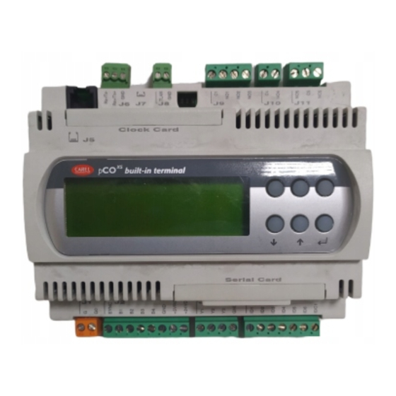
- Page 11 Di seguito viene fornita una descrizione del pCO con riferimento alla The following is a description of the pCO with reference to the layout: planimetria: CLOCK CARD built-in terminal SERIAL CARD Fig. 2.1.1 Power supply connector [G (+), G0 (-)] 24Vac or 20/60Vdc; Connettore per l’alimentazione [G (+), G0 (-)] 24Vac o 20/60 Vdc;...
- Page 12 2.2 Significato degli ingressi/uscite 2.2 Meaning of the inputs/outputs Questa tabella riassume la corrispondenza ingressi - uscite ed una loro This table summarises the inputs and the outputs and provides a brief breve descrizione. description of each. connettore segnale descrizione connector signal description...
- Page 13 3. IL TERMINALE UTENTE 3. THE USER TERMINAL 3.1 Regolazione del contrasto dei display a LCD 3.1 Adjusting the contrast on the LCD display I modelli con display LCD 4x20 sono dotati di potenziometro per la The models with 4x20 LCD display have a trimmer for adjusting the regolazione del contrasto del display.
- Page 14 3.4 Display LCD grafico montaggio a parete o pannello 3.4 Graphic LCD display for wall or panel mounting Caratteristiche Characteristics codice PCOT00PGH0 code PCOT00PGH0 128x64 pixel, grafico, 128x64 pixels, retroilluminato graphic, backlit Room 1 Graphic Temp 128x64 pixel, grafico, 128x64 pixels, retroilluminato graphic, backlit numero righe...
- Page 15 3.7 Display a 3 cifre LED 32x72 3.7 3 digit LED display, 32x72 Caratteristiche Characteristics codice PCOT32RN00 code PCOT32RN00 numero cifre LED number of LED digits numero tasti number of buttons mute Fig. 3.7.1 3.8 pCO terminal keypad 3.8 Tastiera terminali pCO description descrizione mechanical buttons covered by polycarbonate...
- Page 16 3.8.1 Utilizzo tipico dei tasti nelle applicazioni standard Carel 3.8.1 Typical functions of the buttons in standard Carel applications menu visualizza i valori rilevati dalle sonde; menu displays the values measured by the probes; visualizza i valori relativi alla manutenzione dei dispositivi (ore displays the values correspond.
- Page 17 3.9.1 Scheda display grafico 3.9.1 Graphic display board La scheda supporta il microprocessore, le memorie e la EPROM, The board supports the microprocessor, the memory and the EPROM contenente il programma applicativo di gestione del display e della that stores the application program for managing the display and the tastiera.
- Page 18 3.9.3 Scheda schermo (opzione per stampante) 3.9.3 Protective shield (optional printer card) Per tutti i modelli del terminale grafico pCO For all pCO graphic terminal models an esiste la possibilità di inserire una scheda optional card can be inserted in the pin opzionale per la gestione di una stampante connector marked by number 2 in seriale, nel connettore a pettine...
- Page 19 AVVERTENZA: il pCO (come il pCO e pCO ) non può alimentare i WARNING: the pCO (like the pCO and pCO ) cannot be used to terminali grafici PCOT00PGH0 e PCOI00PGL0, che devono quindi power the graphic terminals PCOT00PGH0 and PCOI00PGL0, which essere alimentati con altre sorgenti.
- Page 20 The pCO can be connected to all the Carel AS* series active temperatura ed umidità della serie AS* Carel, configurate come 0/1 V temperature and humidity probes configured as 0/1V (only for humidity (solo per segnale umidità e non per temperatura) oppure come 4/20 mA.
- Page 21 The pCO can be connected to all the Carel SPK* series active della serie SPK* Carel o qualsiasi sensore di pressione presente sul pressure probes or any other pressure sensor available on the market mercato con segnale 0/20 mA o 4/20 mA. Gli ingressi che possono with a 0/20mA or 4/20mA signal.
- Page 22 The pCO can be connected to all the Carel SPKT series active pro- della serie SPKT Carel o qualsiasi sensore di pressione presente sul bes pressure or any other pressure sensor available on the market with mercato con segnale 0/5 V raziometrico.
- Page 23 4.5 Collegamento degli ingressi digitali 4.5 Connecting the digital inputs Il pCO prevede fino a 6 ingressi digitali, contatto pulito, per il The pCO features up to 6 digital inputs, with voltage-free contacts, for collegamento a sicurezze, allarmi, stati di dispositivi, consensi remoti, connecting safety devices, alarms, device status indicators, remote etc.
- Page 24 4.6 Collegamento delle uscite analogiche 0/10 Vdc 4.6 Connecting the 0/10Vdc analogue outputs Il pCO fornisce due uscite analogiche a 0/10 V. La Fig. 4.6.1 The pCO provides two 0/10V. Fig. 4.6.1 shows the electrical rappresenta lo schema elettrico di collegamento. connection diagram.
- Page 25 4.8 Collegamento delle uscite digitali 4.8 Connecting the digital outputs Il pCO prevede fino a 5 uscite digitali con relè elettromeccanici. The pCO features up to 5 digital outputs with electromechanical relays. Per facilità d'assemblaggio i morsetti comuni dei primi 3 relè sono stati For ease of installation, the common terminals of the first 3 relays have raggruppati.
- Page 26 The connection between the user terminal and the pCO is made cavo telefonico a 6 vie, fornito da Carel. Per effettuare il collegamento using a 6-way telephone cable supplied by Carel. To make the basta inserire il connettore telefonico nel morsetto J10 del pCO...
- Page 27 4.9.2 Installazione dei terminali da pannello (pCOI) e relativi 4.9.2 Installing the panel-mounted terminals (pCOI) and collegamenti elettrici corresponding electrical connections These terminals have been designed for panel mounting; the drilling Questi terminali sono stati studiati per il montaggio a pannello, con template must measure 173x154 mm.
- Page 28 (nodo) ad un’altra. information from one location (node) to another. Ogni pCO può inoltre essere collegato alla rete di supervisione Carel, Each pCO can be connected to a Carel supervisory network, using mediante le schede opzionali PCO1004850.
- Page 29 4x20 standard. Tramite le seguenti operazioni: • Disconnect the pCO from the power supply; • Disalimentare il pCO • Organise a standard Carel 4x20 LCD terminal with the address set • Predisporre un terminale LCD 4x20 standard Carel con indirizzo to 0; selezionato su 0;...
- Page 30 5.3 Terminali privati e condivisi 5.3 Private and shared terminals Each pCO board, connected to the network, can manage more than Ogni scheda pCO connessa alla rete pLAN, può gestire più terminali one terminal (max 3) at the same time. The display of the values on contemporaneamente (max 3).
- Page 31 Note: the earth connection can be made to terminal G; this Attenzione: il collegamento a terra può essere eseguito sul morsetto configuration is possible as the pCOXS has an insulated power supply. G, questa configurazione è possibile perchè il pCO ha un alimentatore isolato.
- Page 32 5.5 Remotazione terminale con rete pLAN 5.5 Remote installation of the terminal in a pLAN network Quando le schede pCO sono connesse in rete pLAN il terminale può When pCO boards are connected in a pLAN network, the terminal essere remotato fino a 50 metri usando cavo di tipo telefonico, mentre can be remotely-installed at a distance of up to 50 metres, using a può...
- Page 33 5.5.2 Remotazione terminale fino a 200 m con rete pLAN con cavo 5.5.2 Remote installation of the terminal at up to 200m in a pLAN schermato AWG24 con 3 coppie ritorte + schermo network using an AWG24 shielded cable with 3 twisted pairs + screen Questo tipo di remotazione è...
- Page 34 RS485 baud-rate (kbit/s) 65,2 baudrate (kbit/s) 65.2 protocollo Multimaster (protoc. di proprietà Carel) protocol Multimaster (Carel proprietary protocol) lunghezza max. della rete (m) max. length of the network (m) 500 Tab. 5.6.1 Table 5.6.1 manual - cod. +030220345 - rel. 1.0 - 18.03.03...
- Page 35 The pCO controller allows direct connection over two lines to the new nuova rete Carel “tLAN” o verso tutti i attuatori per serrande e valvole Carel “tLAN” network or to all Belimo actuators for dampers and water acqua della Belimo: rete MP Bus (in quanto gli attuatori devono essere valves: Mp Bus network (in this case the actuators have to be supplied alimentati separatamente).
- Page 36 In ogni attuatore Belimo è possibile collegare anche un sensore di Each Belimo actuator can also be connected to an active or passive temperatura, attivo o passivo, o un contatto digitale. Tali sensori devono temperature sensor, or a digital contact. These sensors must be con- essere collegati al morsetto 3 dell’attuatore e i collegamenti variano in nected to terminal 3 on the actuator, and the connections vary accor- funzione del tipo di sensore utilizzato, sono acquisiti dall’attuatore e...
- Page 37 9 poli maschio connecting the printer using a serial printer (connettore A) dove collegare la cable, 9-pin (pCOXS end) - 25 pin (printer stampante tramite cavo seriale per end). stampante 9 poli (lato pCOXS) - 25 poli (lato stampante).
- Page 38 7.5 Scheda per stampante seriale per terminale grafico 7.5 Serial printer card for graphic terminal, PCOSERPRN0 PCOSERPRN0 The printer card is an optional card only for the pCO graphic terminal La scheda stampante è un una scheda opzionale solo per i modelli del models (code PCOI00PGL0 and PCOT00PGH0).
- Page 39 Questa interfaccia permette di fundamental parameters of the OEM controllare i parametri fondamentali humidifiers manufactured by Carel (level degli umidificatori OEM prodotti da Carel and conductivity of the water in the (livello e conducibilità acqua nel cilindro, cylinder, TAM sensor for current input)
- Page 40 Dopo 20 sec. viene ripristinato nel pCO il protocollo originario. WinLoad non adatto o Password di Protezione Software errata. in comunicazione con WinLoad. usato come Espansione I/O Protocollo Supervisore Carel (slave) attivo sulla seriale 0. RED LED YELLOW LED GREEN LED NOT in pLAN (address= 0) correct operation with or without local terminal.
- Page 41 *: casi in cui pCO regredisce allo stato Basso Livello: *: cases in which pCO reverts to Low Level status: - In fase di avvio il pCO rileva la presenza del WinLoad collegato. - When starting the pCO detects that WinLoad is connected. - In fase di avvio il pCO rileva “Application corrupted…”.
- Page 42 9. Schema generale dei collegamenti elettrici 9. General diagram of the electrical connections Di seguito viene indicato un esempio (Figg. 9.1) di collegamenti elettrici Below are one example (Figs. 9.1) of the electrical connections of the del pCO ai vari dispositivi. to the various devices.
- Page 43 10. CARATTERISTICHE TECNICHE DEL pCO 10. TECHNICAL SPECIFICATIONS OF THE pCOXS 10.1 Caratteristiche generali 10.1 General characteristics condizioni di immagazzinamento -20T70, 90% UR non condensante (versione standard) -30T80, 90% UR non condensante (vers. range esteso con display built-in) -55T85, 90% UR non condensante (vers. range esteso di temp. no display built-in)
- Page 44 A/D converter a 10 bit CPU built-in; tipo B1, B2: sens. di temp. NTC Carel (-50T90 °C; R/T 10 kΩ a 25 °C), tensione: 0/1 Vdc o 0/5 Vdc raziometrici, corrente: 0/20 mA o 4/20 mA, selezionabili via software. Resistenza di ingresso in 4/20mA= 100Ω;...
- Page 45 10.2.2 Digital inputs number of digital inputs type of digital inputs voltage-free contact (powered by the pCO contact current 6mA guaranteed minimum normally-open digital input detection time (open-closed-open) in AC and DC (ms) minimum normally-closed digital input detection time (closed-open-closed) in AC and DC (ms) Table 10.2.2.1 Separate the probe signal and digital input cables as much as possible Separare quanto più...
- Page 46 10.3 Contenitore plastico pCO 10.3 pCO plastic case Agganciabile su guida DIN secondo Norme DIN 43880 e secondo Can be mounted on DIN rail according to DIN 43880 and EN 50022 Norme EN 50022 standards Materiale: tecnopolimero Material: technopolymer Autoestinguenza V0 (secondo UL94) e 960 °C (secondo IEC 695) Self-extinguishing V0 (according to UL94) and 960°C (according to IEC 695) Prova biglia: 125 °C Marble test: 125°C...
- Page 47 • Policarbonato tastiera (standard Carel) per PCOT*CB* e PCOI* • Polycarbonate keypad (Carel standard) for PCOT*CB* and PCOI* spessore (mm) 0,175 thickness (mm) 0.175 trattamento serigrafia a 4 colori processing 4-colour silk screening Tab. 11.4.1.3 Table 11.4.1.3 Nota: Il contenitore standard (PCOT*BC*) prevede uno sportellino che Note: The standard case (PCOT*BC*) features a features a door that si apre sul frontale con un’inclinazione massima di 150˚.
- Page 48 12. MONTAGGIO TERMINALE UTENTE 12. USER TERMINAL INSTALLATION 12.1 Montaggio a pannello 12.1 Panel installation 12.1.1 PCOT* 12.1.1 PCOT* Riferimenti Fig. 12.1.1.1, (dimensioni in mm). Key to Fig. 12.1.1.1, (dimensions in mm). n. descrizione description coperchio posteriore rear cover pannello panel coperchio anteriore front cover...
- Page 49 13. DIMENSIONI 13. DIMENSIONS AVVERTENZA: tutte le quote riportate sulle figure che seguono sono WARNING: all the distances shown in the figure below are expressed espresse in mm. in mm. 13.1 pCO 13.1 pCO Fig. 13.1.1 13.2 Terminale utente 12.2 User terminal 13.2.1 PCOT* 13.2.1 PCOT* 170 mm...
- Page 50 6. se si è in presenza di errore di sonda oppure se si tratta di un conductive paste or oil into the caps to ensure good temperature errore di conversione del pCOXS, le verifiche si diversificano a transfer; seconda del tipo di sonda: 6.
- Page 51 Sonde attive di temperatura/umidità con segnale 0/1 V: Active temperature/humidity probes with 0/1V signal: misurando con un voltmetro tra i morsetti Bn e GND si ha il segnale di measure, using a voltmeter between terminals Bn and AVSS, the sonda e si puó verificare la corrispondenza tra tensione e grandezza: 1 probe signal and check that the voltage corresponds to the mVdc corrisponde a 0,1°C temperature/humidity value: 1mVdc corresponds to 0.1°C...
- Page 52 1. che i cavi di potenza non passino nelle vicinanze dei the main board; microprocessori della scheda base; 2. that the ratings of the power transformer (not supplied by CAREL) 2. che il dimensionamento del trasformatore di alimentazione (non are correct (see paragraph on POWER) fornito da CAREL) sia corretto (vedi paragrafo ALIMENTAZIONE);...
- Page 56 Agenzia / Agency: CAREL S.p.A. Via dell’Industria, 11 - 35020 Brugine - Padova (Italy) Tel. (+39) 049.9716611 - Fax (+39) 049.9716600 e-mail: carel@carel.com - www.carel.com...
Need help?
Do you have a question about the pCOXS and is the answer not in the manual?
Questions and answers