Advertisement
Quick Links
Advertisement

Related Manuals for UNI-T UT-P43 Series


Summary of Contents for UNI-T UT-P43 Series
- Page 1 UT-P43&UT-P44 Series Current Probe Instruction Manual...
- Page 2 UT-P43&UT-P44 Series Current Probe Instruction Manual Please read the instruction manual carefully to avoid injury and prevent damage to this product. Ver. 1.03 2021-5-17...
- Page 3 Please read the manual carefully prior to use the product. Warranty UNI-T warrants that this product will be free from defects in materials and workmanship for a period of one (1) year from the date of shipment. If any such product proves defective during this warranty period, UNI-T,...
-
Page 4: Table Of Contents
Table of contents 1. Safety Summary …………………………………………4 2. Brief Introduction…………………………………………5 3. Main Specification ………………………………………6 4. Unpacking and Preparation for Use ………………………8 5. General View of Product …………………………………9 6. General View of Accessories………………………………10 7. Operating Basics …………………………………………11... -
Page 5: Safety Summary
1. Safety Summary Please Review the following safety precautions to avoid injury and prevent damage to this product or any products connected to it. Use proper AC adapter. Use only the AC adapter specified for this product. Connect and disconnect properly. Connect the probe output to the measurement instrument before connecting the probe to the circuit under test. -
Page 6: Brief Introduction
2. Brief introduction UT-P43&UT-P44 series current probe applies Advanced magneto-electric sensors. It is used to measure the circuit current with an oscilloscope Using electromagnetic induction and magneto-electric induction. UT-P43&UT-P44 series current probe can measure 20A (DC + peak AC) or 40A(DC + peak AC)current. The frequency bandwidth of measured signal is 25MHz or 50MHz. -
Page 7: Main Specification
3. Main Specifications Electrical Specification UT-P43 UT-P44 Model Bandwidth (-3dB) 25MHz 50MHz Rise time 14ns Max. measurable current 20A(DC + peak AC) 40A(DC + peak AC) Current transfer ratio 100mV/A 50mV/A Accuracy ± 3% Max. measurable pulse 50A(Tp ≤10μs) current Max. - Page 8 Probe body 188×40×24(mm) Weight (probe only) 150g Environment Specification Operating temperature 0~40℃ Storing temperature -10~45℃ Operating humidity 85%RH Storing humidity 90%RH Operating altitude 3000m Storing altitude 12000m...
-
Page 9: Unpacking And Preparation For Use
4. Unpacking and Preparation for Use 4-1 Unpacking This product has been checked and tested for the quality before it comes out of the factory. Please check if there is damage during the transportation when unpacking. If there is, please inform the transportation company and the local agent immediately. -
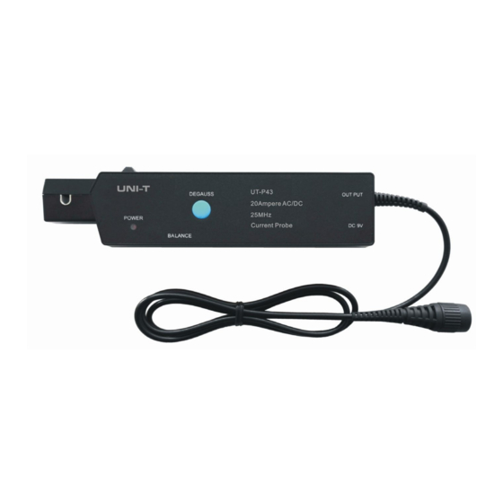
Page 10: General View Of Product
5. General View of Product... -
Page 11: General View Of Accessories
6. General View of Accessories The product include an accessories: An AC adapter... -
Page 12: Operating Basics
7. Operating Basics UT-P43&UT-P44 series current probe is very convenient to operate. But we suggest every new user should read the manual perfectly prior to begin operating. 7-1 Operation steps a. Check and affirm the AC adapter input voltage is correct prior to use. - Page 13 probe jaw to get out the wire. Figure7-1 Figure7-2 7-2 Attention to use: a. To measure differential or null current, you can place two wire in the probe jaw. b. If you are measuring DC or low-frequency AC signal of very small amplitudes, you can increase measurement sensitivity of your current probe by winding several turns of the wire under test around the probe as shown in Figure 7-2.
Need help?
Do you have a question about the UT-P43 Series and is the answer not in the manual?
Questions and answers