Sign In
Upload
Download
Table of Contents
Contents
Add to my manuals
Delete from my manuals
Share
URL of this page:
HTML Link:
Bookmark this page
Add
Manual will be automatically added to "My Manuals"
Print this page
×
Bookmark added
×
Added to my manuals
Manuals
Brands
UNI-T Manuals
Measuring Instruments
UTL8500 Series
User manual
UNI-T UTL8500 Series User Manual
Programmable dc electronic load
Hide thumbs
1
2
3
4
5
Table Of Contents
6
7
8
9
10
11
12
13
14
15
16
17
18
19
20
21
22
23
24
25
26
27
28
29
30
31
32
33
34
35
36
37
38
39
40
41
42
43
44
45
46
47
48
49
50
51
52
53
page
of
53
Go
/
53
Contents
Table of Contents
Bookmarks
Table of Contents
Preface
Copyright Information
Warranty Service
Guarantee Limit
Safety Information
Safety Symbols
Table of Contents
1 Product Description
Product Series
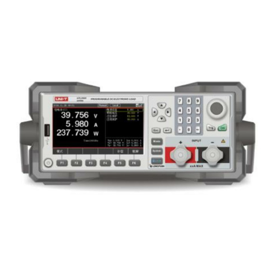
Front Panel
Rear Panel
2 Inspection and Installation
Packing List
Requirements of Power Supply
Operating Environment
Cleaning
Handle of Instrument
3 Display Page of Measurement
Power on and Run
Introduction of Screen Display
Display of Measurement Interface
Introduction of Status Bar
Running Indicator
4 Measurement Setting
Constant State Test Modes
Constant Current Test
Constant Voltage Test
Constant Resistance Test
Constant Power Test
More Modes
Dynamic Mode
List Mode
Dual Mode
OCP/OPP Mode
CR-LED Mode
Battery Mode
Load Effect
OVP Mode
Short-Circuit Mode
Time Mode
Parameter Input and Loading Measurement
Numeric Key
Pulse Knob
Ripple Measurement
Input Control
Trigger Method
Sense
Screenshot
Saving and Applying of Configuration
5 System Configuration Page
System Configuration
Language
Key Sound
Date
Warn Sound
Time
DIM Display
Initial Mode
Knob Active
Communication Setting
Restore Factory Setting
Parameter Setting
File
Instrument Info
Local/Remote
6 Communication Interface and Terminal
7 Technical Specifications
Advertisement
Quick Links
1
Preface
2
Product Series
3
Constant Current Test
4
Battery Mode
5
Communication Interface and Terminal
6
Technical Specifications
Download this manual
UTL8500 Series
Programmable DC Electronic Load
User Manual
Table of
Contents
Previous
Page
Next
Page
1
2
3
4
5
Advertisement
Table of Contents
Need help?
Do you have a question about the UTL8500 Series and is the answer not in the manual?
Ask a question
Questions and answers
Related Manuals for UNI-T UTL8500 Series
Test Equipment UNI-T UTL8500+ Series User Manual
Dc electronic load (64 pages)
Measuring Instruments UNI-T UTL8511 User Manual
Programmable dc electronic load (53 pages)
Measuring Instruments UNI-T UTL8512 User Manual
Programmable dc electronic load (53 pages)
Measuring Instruments UNI-T UTL8500X Series User Manual
Programmable dc electronic load (73 pages)
Measuring Instruments UNI-T UTL8511S User Manual
Programmable dc electronic load (73 pages)
Measuring Instruments UNI-T UTL8200+ Series User Manual
Dc electronic load (34 pages)
Measuring Instruments UNI-T UT30A Operating Manual
(33 pages)
Measuring Instruments UNI-T UT253A Operating Manual
Large jaw leakage current clamp meter (12 pages)
Measuring Instruments UNI-T UT255B Operating Manual
High voltage clamp ammeters (20 pages)
Measuring Instruments UNI-T UT312 Operating Manual
Pocketable vibrometer (7 pages)
Measuring Instruments UNI-T UT206B Operating Manual
1000a true rms digital clamp meter (21 pages)
Measuring Instruments UNI-T UT-213C User Manual
Clamp meter (6 pages)
Measuring Instruments UNI-T UTR2810E Series User Manual
Lcr meter (34 pages)
Measuring Instruments UNI-T UTS1015B Service Manual
Spectrum analyzers (26 pages)
Measuring Instruments UNI-T UTE9800+ Series User Manual
Smart digital power meter (56 pages)
Measuring Instruments UNI-T UTR2830 Series User Manual
Digital lcr meter (98 pages)
This manual is also suitable for:
Utl8511
Utl8512
Utl8512b+
Utl8513
Table of Contents
Print
Rename the bookmark
Delete bookmark?
Delete from my manuals?
Login
Sign In
OR
Sign in with Facebook
Sign in with Google
Upload manual
Upload from disk
Upload from URL


Need help?
Do you have a question about the UTL8500 Series and is the answer not in the manual?
Questions and answers