
Related Manuals for UNI-T UT-P33


Summary of Contents for UNI-T UT-P33
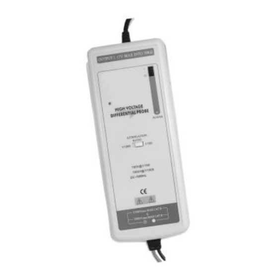
- Page 1 有源差分探頭 Differential Probe Active Probe UT-P30 ■ UT-P33 ■ INSTRUCTION MANUAL 使 用 說 明 書...
-
Page 2: Table Of Contents
目錄 1、簡述.........1 2、規格.........1 3、操作環境及狀況.......2 4、操作程序......3 5、 維護........3 6、 清潔.........4 7、 保固.........4 8、 維修.........4 CONTENTS Features......1、 Specifications..... 2、 Operating environmental conditions..3、 Operating procedure....4、 Maintenance...... ▉ Cleaning......▉ Warranty......▉ Repair......▉... - Page 3 UT-P33 差動測試棒提供一個安全的儀器給 所有的示波器使用, 它可以轉換由高輸入的差動電 壓(≤14KVPEAK)進入一個低電壓(≤7V), 並且顯示 波形在示波器上, 使用頻率高達 120MHz, 非常適合 大電力測試、研發、維修使用。 差動測試棒輸出標示是設計在操作示波器 1MΩ的輸入阻抗的相對衰減量, 當使用 50Ω 匹 配 器進衰減量剛好爲 2 倍量。 UT-P33 差動測試棒, 也建議選購本公司生産 的 PL-10 阻抗轉換器,可以延伸差動測試棒的應 用範圍-可以在電錶上 觀測更精確的實際測量電 壓值(示波器精確度 爲 1%,數位電錶約精 准 10 倍)。 二、規格: (1) 頻寬: DC-120MHz (2) 衰減:x100,x1000 (3) 精確度:±1%...
- Page 4 最高差動電壓:14KV(DC+AC PEAK TO PEAK) 輸入端及接地端間最高電壓:5KV RMS (6) 輸入阻抗: 差動:20MΩ /1pF 單端到接地端間的輸入阻抗:10MΩ /2pF (7)輸出電壓:≤7V (8)輸出 阻抗:50Ω (9)上升時間: (10)雜訊抑制率: 60Hz:>80dB;100Hz:>60dB;1MHz:>50dB (11)指定外接 6V DC 電源 (12)耗電:最大耗電量 150mA(0.9 瓦特) 三、操作環境及狀況 一般狀態 使用操作中 儲存 +20℃…+30℃ 0℃….+50℃ -30℃….+70℃ 溫度 濕度 ≤70%RH 10%…85%RH 10%…90%RH (1) 尺寸及重量:69x26x165mm; (2) 電子安全規範 IEC 1010-1 雙絕緣...
- Page 5 四、操作程式 將 BP-250 與 UT-P33 的輸出端連接,並與示波 器連結。 如有需要先調整示波器上的垂直開關。 將示波器上的衰減率及垂直開關調整到一致的 位置,如下表。 注意:電源必須打開。 衰減 X1000 X100 輸 入 電 壓 14KV 1.4KV (DC+AC Peak) (注意) 實際的垂直偏向是等於衰減乘上示波器上所選擇 的垂直偏向,例如是使 用負載 50Ω的兩倍。 五、維護 保養此産品時請使用原廠指定的工具, 原廠將 不負任何責任由其他不被認可的維修人員所 做的維修。...
- Page 6 六、清潔 此産品不需要任何特定的清潔,如有需要,請 用輕軟乾淨的布沾上微量的清潔液輕輕的在産 品外觀擦拭。 七、保固 除了在人爲上的特意損壞, 本産品是受保固並 可以維修的,並不包含在安全規範的責任。 保固是以不超出發票上的金額, 零件的更換及 運送的費用。 保固是僅在正常操作下而造成的損壞, 並不包 含任何刻意的損壞,操作上的錯誤, 機械上的 操作不當, 保養不當,負載或過壓。 原廠的保固是賣出後的 12 個月內,如有任意 的非原廠的維修或更換零件,原廠保固將自然 取消。 八、維修 有任何的維修,保養或更換零件是在保固以外,請 將産品退回原廠維修。...
-
Page 7: 1、 Features
120MHz,which is ideal for big power testing,development and maintain. The UT-P33 is designed to operate with the 1MΩ impedance oscilloscopes. When combine with the 50Ω load , the attenuation will be 2 times. - Page 8 (4) Input voltage range(DC+AC PEAK TO PEAK ) ≤1.4KV for x100,(about 490V RMS) ≤14KV for x1000,(about 4900V RMS ) (5) Permitted max input voltage: Max differential voltage: 14KV(DC+AC PEAK to PEAK) Max voltage between each input terminal and ground: 5KV RMS (6)Input Impedance: Differential: 20MΩ...
-
Page 9: Operatingenvironmental Conditions
3.Operatingenvironmental conditions Reference Storage +20℃…+30℃ 0℃….+50℃ -30℃….+70℃ Temperature Relative Humidity ≤70%RH 10%…85%RH 10%…90%RH (1) Dimensions and weight:245X84X36mm; 500g (2) Electrical safety to IEC 1010-1 Dual insulation Installation category Ⅲ Degree of Pollution 2 Related voltage or max line-earth:5KV RMS CE:EN50081-1 and 50082-1 4.Operating procedure ․... -
Page 10: Maintenance
․ NB: The POWER light must come on. Attenuation ratio X1000 X100 Voltage Input Range 14KV 1.4KV (DC+AC Peak to PEAK) [N.B] The real vertical deviation in V/div is equal to the attenuation factor multiplied by the range of vertical deviation selected on the oscilloscope. -
Page 11: Warranty
▉ Warranty Unless notified to the country,our instruments are guaranteed against any manufacturing defect or material defect. They do not bear the specification known as the safety specification. Our guarantee,which may not under any circumstances exceed the amount of the invoiced price,goes on further than the repair of our faulty equipment,carriage paid to our workshops.
Need help?
Do you have a question about the UT-P33 and is the answer not in the manual?
Questions and answers