
Related Manuals for UNI-T UT-P4000 Series


Summary of Contents for UNI-T UT-P4000 Series
- Page 1 DC/AC Current Probes UT-P4000 Series UT-P4030D 30A/ DC~100MHz UT-P4150 150A/ DC~12MHz UT-P4500 500A/ DC~5MHz www.uni-trend.com...
-
Page 2: Safety Notices
Safety Notices A CAUTION notice denotes a hazard. It calls attention to an operating procedure, practice, or the like that, if not correctly performed or adhered to, could result in damage to the product or loss of important data. Do not proceed beyond a CAUTION notice until the indicated conditions are fully understood and met. -
Page 3: Table Of Contents
7.3 Measuring method ........................15 The method to deal with abnormal situation ................16 Q&A ..............................16 9.1 Does UT-P4000 series fit the oscilloscope of any brand? ............. 16 9.2 Can UT-P4000 series product measure small current? ..............16 9.3 Anymore tips? ..........................16... -
Page 4: Features And Applications
1. Features and Applications The UT-P4000 series current probes are wide band width DC/AC active current probes, featuring high bandwidth, fast and accurate capture the current wave, accuracy up to 1% and low circuit insertion loss. This probe can be used with any oscilloscope having a high-impedance BNC input. -
Page 5: Description Of Products
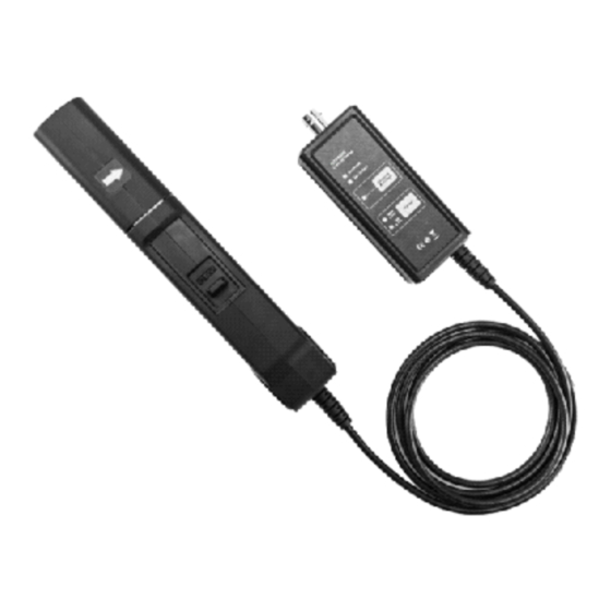
2. Description of products UT-P4030D UT-P4150、UT-P4500 1) Sensor Head The core component to measure conductor current. The component contains a precise semi-conductor that could be damaged by drastic change of environmental temperature, external pressure and shock. Please be careful during measurement. 2) Opening lever The operating lever used to open the sensor head. -
Page 6: Making Measurements
3. Making Measurements Before using the probe, check that the system is safe and that the preparations described in Safe Probing. Have a visual inspection of the current probe of high frequency UT-P4000 Series probes, power supply, cable, and oscilloscope. ... -
Page 7: Safe Probing
into the LOCKED position as shown in Figure. Confirm that the sensor head is properly closed. Degaussing and Zero Setting When the key is pressed, the probe will demagnetize the core and set the output to zero voltage if it has been magnetized by switching the power on and off, or by an excessive input. - Page 8 Make sure that the waveform measuring equipment connected to this device's output terminal (BNC) is equipped with a protective earthling with double-insulation construction. Do not allow the device to get wet, and do not take measurements with wet hands. This ...
- Page 9 measured. The facing surface of the core section can be scratched while it is open. Do not place any un-clamped conductor with an electric current of a frequency of 10 kHz or more near the sensor head. Current flowing in the conductor nearby may heat up the sensor head and cause its temperature to rise, leading to damage to the sensor.
-
Page 10: Accessories Description
Under certain circumstances, oscillation may occur if the probe is connected to the power supply while the power supply is on. This does not indicate a malfunction. Oscillation can be stopped and operation restored to normal by opening and closing the sensor head. Depending on the measured current frequency, some sound maybe produced by resonance, ... - Page 11 Rise time ≤3.5ns ≤29ns ≤70ns 30Arms 150Arms 500Arms Continuous maximum (Figure2) (Figure5) (Figure8) input range Max peak current 50Apk 300Apk 750Apk value 5A(1X) 0.05A~5A 30A(10X) 0.3A~30A 75A(10X) 0.3A~75A Range (RMS) 30A(10X) 0.3A~30A 150A(100X) 1.5A~150A 500A(100X) 5A~500A ≥5Apk ≥30Apk ≥75A Overload ≥50Apk 150A ≥300Ap...
- Page 12 Figure1 UT-P4030D Amp- Frequency curve Figure2 UT-P4030D Figure3 UT-P4030D Continuous maximum input measurement Input impedance VS Frequency curve Figure4 UT-P4150 Amp- Frequency curve Figure5 UT-P4150 Figure6 UT-P4150 Continuous maximum input measurement Input impedance VS Frequency curve...
-
Page 13: Mechanical Characteristic
Figure7 UT-P4500 Amp- Frequency curve Figure8 UT-P4500 Figure9 UT-P4500 Continuous maximum input measurement Input impedance VS Frequency curve 6.2 Mechanical characteristic Model UT-P4030D UT-P4150 UT-P4500 Measurement conductor 20mm diameter max. Cable length 1.5m BNC Cable length 100cm Adapter dimensions 62*58*29mm line:1.5m Clamp dimensions (L*W*H) 176*39.5*18mm 174*67.5*30mm... -
Page 14: Environmental Characteristic
Probe weight 255g 555g 525g 6.3 Environmental characteristic Operating temperature and humidity 0-40℃, ≤80% RH Storage temperature and humidity -10-50℃, ≤80% RH Operating altitude ≤2000m Storage altitude ≤12000m 7. Operating Method Note The output interface of this machine is set inside. When using the oscilloscope, please select high input resistance (1MΩ). -
Page 15: Preparation Before Testing
At the lock state, please do not press the entire part as shown below. 7.1 Preparation before testing Prepare the high frequency current probe UT-P4000 series, adapter and oscilloscope Power up the UT-P4000 probe and the green LED power indicator will be lighted. -
Page 16: The Method To Deal With Abnormal Situation
9.1 Does UT-P4000 series fit the oscilloscope of any brand? A: UT-P4000 series has standard BNC interface can be applied to the oscilloscope of any brand. It is powered by standard adapter, independent of oscilloscope power, so it is very easy to use. -
Page 17: Packing List
Make sure the probe is locked during testing. The probe should be away from the interference source like transformer. The method to judge if the probe is interfered is to put the probe close to circuit under test. IF there’s any output, there could be interference in the testing environment because the probe is not on the circuit yet.
Need help?
Do you have a question about the UT-P4000 Series and is the answer not in the manual?
Questions and answers